
Related Manuals for AeroWorks 50cc EXTRA 260 ARF-QB


Summary of Contents for AeroWorks 50cc EXTRA 260 ARF-QB
- Page 1 50cc EXTRA 260 ARF-QB (Quick Build) ASSEMBLY MANUAL AEROWORKS 401 Laredo Unit “D”, Aurora, CO. 80011 - Phone 303-366-4205 - Fax 303-366-4203 E-mail - info@aero-works.net...
-
Page 2: Table Of Contents
TABLE OF CONTENTS Page Aeroworks Contact Information ………………………………………………………………. 3 Introduction ……………………………………………………………………………………... 4 Kit Contents……………………………………………………………………………………… 5 Items Needed To Complete ……………………………………………………………………... 7 Tightening and Re-shrinking The Covering ………………………………………………….. 8 Check Seams and Overlaps for Good Seal ……………………………………………………. 9 Applying clear covering to the leading edges of wings and stabs ……………………………. 10 Wing Assembly………………………………………………………………….……………….. - Page 3 Further, Aeroworks reserves the right to change or modify this warranty without notice. In that Aeroworks has no control over the final assembly or materials used for final as- sembly, No liability shall be assumed nor accepted for any damage resulting from the use by the user of the final user-assembled product.
-
Page 4: Intended Use
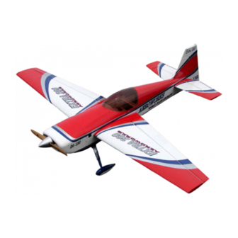
INTRODUCTION Your new 50cc EXTRA 260 ARF-QB is a highly aerobatic airplane. It is capable of both pre- cision and 3-D maneuvers. The aircraft builds easily, quickly, and precisely due to its state of the art CAD design, LASER cut technology, and high quality included hardware. We hope you enjoy building and flying your 50cc EXTRA 260 ARF-QB. -
Page 5: Kit Contents
KIT CONTENTS (4) #6 bonded washers for the mounting of the 50cc Extra 260 ARF-QB Canopy Materials List (2) pull-pull exit tubes for rudder cable installed (1) Antenna Tube installed Basic Aircraft Parts (1) engine box hatch cover, installed Fuselage with pre-installed vertical fin – covered, Left Wing with Aileron –... - Page 6 Horizontal Stabilizer with elevator assembly with (8) (2) 4-40 3” two end threaded pushrod with nuts for pin point hinges (glued)---covered, pre-drilled for control ailerons horns. (2) 4-40 4” two end threaded pushrod with nuts for elevators. Rudder with (5) pin point hinges (not glued) – covered, (2) 4-40 x250mmThreaded pushrod - throttle and choke.
-
Page 7: Items Needed To Complete
ITEMS NEEDED TO COMPLETE Hardware • Allen wrenches US and Metric. • Dremel cutting disc and sanding drum tool • Electric drill and selection of bits • Razor saw • Flat head screwdriver • Hobby heat gun • Hobby iron and covering sock •... -
Page 8: Tightening And Re-Shrinking The Covering
TIGHTENING AND RE-SHRINKING THE COVERING 1. Open your kit slowly and take care not to dam- 3. If bubbles persist, use a small pin to punch holes age any parts of the kit. Remove all parts from in the bubble to relieve trapped air and reheat. their plastic protective covers for inspection. - Page 9 It is the users responsibility to check the covering seams and overlaps for security and a good seal. Aeroworks is not re- sponsible for failure of covering seams or overlaps during flight. This is a never ending process that must be done after each flying secession.
-
Page 10: Applying Clear Covering To The Leading Edges Of Wings And Stabs
Applying clear covering to the leading edge of wings and stabs. In order to complete this step you will need: 3. Seal the top and bottom of the leading edge carefully to insure the covering is securely Clear covering, Covering Iron, Scissors, attached to the wood underneath. - Page 11 5. Cut the covering even with the wing tip being 7. Remove the clear backing from the covering. careful not to cut it to short. Note: Do not skip this step. There is a backing to the covering. Take time to remove this backing to get the correct adhesion to the already applied covering.
- Page 12 IMPORTANT It is the users responsibility to check the covering seams and overlaps for security and a good seal. Aeroworks is not re- sponsible for failure of covering seams or overlaps during flight. This is a never ending process that must be done after each flying secession.
-
Page 13: Wing Assembly
WING ASSEMBLY Attach the 18” extension to the servo lead and Aileron Servo Installation secure with safety wire, string, tape, or other method. Ensure the plugs will not come apart The ailerons have been pre-hinged and glued from vibration or light tension. to the wing panels and are ready for flight. - Page 14 Draw the 18” servo extension through the Remove servo and use a 1/16 bit to drill servo wing and pull through the wing root rib. mounting holes. Install servo in servo well with the output arm Install servo with servo mounting screws. toward the leading edge of the wing and mark locations of servo mounting holes.
- Page 15 Aileron servo mounted in bottom of wing. Assemble the pushrod and control horn assem- bly as shown. The ball link goes between the left and right sides of the control horn sides and is secured with a nylon lock nut. Start with the center hole in the control horn.
- Page 16 Use a drop of thick CA glue on each screw as 6. Tape the trailing edge of the aileron to the trail- shown. ing edge of the wing in the neutral position. Plug the servo into the receiver and turn radio on.
-
Page 17: Stab And Elevator Assembly
STAB AND ELEVATOR ASSEMBLY Layout the servo on the fuse to test fit the in- Elevator Servo Installation stallation and ensure servo lead is the correct length. 1. The elevators have been pre-hinged and glued to the stabs and are ready for flight. No other steps are necessary for hinging. - Page 18 5. Install servo in servo cut out with the output Install servo with servo mounting screws. shaft toward the nose and mark locations of servo mounting holes. Remove servo and use a 1/16 bit to drill servo Elevator Control Linkage Installation mounting holes.
- Page 19 Assemble two pushrod and control horn as- Use a drop of thick CA glue on each screw as semblies with servo output arms as shown. shown. The ball link goes between the left and right sides of the control horn sides and is secured with a nylon lock nut.
- Page 20 Tape leading edge of the elevator balance tab to the leading edge of the stab in the neutral position. Plug the elevator servo into the re- ceiver and turn radio on. Ensure the servo trim is centered. Attach the stab and elevator to the fuse and screw in place.
-
Page 21: Rudder And Tail Wheel Assembly
RUDDER AND TAILWHEEL ASSEMBLY Mix epoxy in mixing cup and use a tapered Rudder Installation stick to apply the epoxy inside the pre-drilled holes in the trailing edge of the fin. Apply Gather the rudder, four hinges, rubbing alco- epoxy to one side of each hinge and insert the hol, petroleum jelly and epoxy materials as hinge completely into the hole. -
Page 22: Rudder Servos Installation
Mix epoxy in mixing cup and use a tapered 7. Ensure there is no gap between fin and rudder. stick to apply the epoxy inside the pre-drilled Allow epoxy to fully cure. holes in the leading edge of the rudder. Apply epoxy to trailing edge of each hinge. - Page 23 2. Install the rudder servo in the forward servo cut- Install rudder servo with servo screws. out with the output shaft to the rear. Your model may only have one rudder servo cut out. Only one rudder servo is required for full rudder performance.
- Page 24 Gather the rudder control linkage parts shown Pull the rudder cables from rear of fuse to the below. 2 Rudder cables, 2 threaded metal RC rudder servo tray. links, 4 threaded couplers, and 4 brass swag- ing tubes. Feed one rudder cable through the pre installed Insert rudder cable through the brass swage cable exit tube in the rear of the fuse toward tube, then through the threaded coupler hole,...
- Page 25 Loop the cable back through the brass swage If additional crimping is needed a small C- tube as shown. Clamp may be used for additional crimping pressure. Tighten the second loop through the brass Cut off excess cable as shown swage tube and crimp the brass tube with a crimping tool or pliers.
- Page 26 A drop of thin CA may be applied to the Rudder Control Horn Installation swage tube to help secure the cable. Attach a Gather the rudder control horn parts as shown metal threaded RC link to the threaded cou- below. 2 ball link assemblies, 2 left and 2 pler.
- Page 27 Use a drop of thick CA glue on each screw as 6. Plug the rudder servo into the rudder channel of shown. the receiver and power up. Turn on transmitter to center rudder servo. Ensure servo trim and sub trims are centered. Note: On metal geared servos use Loctite for all Servo arm mounting screws.
- Page 28 Remove ball links from the rudder control Attach ball link to rudder control horn on both horns. Attach two threaded couplers to ball sides of the rudder. Thread the rudder cable links as shown. Thread couplers halfway into through a brass swage tube, then the threaded ball links to allow for correct adjustment.
- Page 29 Tighten the second loop through the brass Cut off excess cable. A drop of thin CA may swage tube as shown. be applied to the swage tube to help secure the cable. Crimp the brass tube with a crimping tool or Hold the threaded coupler below the cable at- pliers.
-
Page 30: Tail Wheel Installation
Re-attach ball link to rudder control horn on Tail Wheel Installation both sides of the rudder. Gather the tail wheel parts shown below. Tail wheel strut and leaf spring, 3 tail wheel mounting screws, steering tiller, 2 tiller mounting screws, and 2 steering springs. With radio on, and rudder centered, adjust rud- Apply a drop of thick CA to the tiller arm der pull-pull cables to desired tension by... - Page 31 Mount the tail wheel steering tiller using two Mount the tail wheel struts and leaf spring wood screws. using three wood screws. Place the tail wheel leaf spring on top of the Attach the steering springs on both sides of the tail wheel strut.
- Page 32 Use pliers to twist spring ends closed around the tillers after desired tension and direction adjustments are complete. Tail wheel final assembly is complete.
-
Page 33: Main Landing Gear Assembly
MAIN LANDING GEAR ASSEMBLY Remove landing gear cover screws. Main Landing Gear Installation Gather the landing gear parts as shown below. Landing gear strut, 4 mounting bolts, washers, and lock washers, 2 wheels, 2 axles, and 4 wheel collars as shown below. Gather the gear strut, 4 mounting bolts, wash- After screws are removed, remove the landing ers, and lock washers, as shown below. - Page 34 Note that the trailing edge of the landing gear Bolt landing gear strut to fuse with 4 bolts, strut is tapered. The tapered edge goes toward lock washers and flat washers. Ensure tapered the rear of the fuse. edge of the gear strut is facing toward the rear. Use a drop of blue Loctite on landing gear Reinstall the gear cover.
- Page 35 Use a drop of blue Loctite and reinstall the Use a drop of blue Loctite on landing gear axle landing gear cover screws. bolt before attaching the landing gear axle with the nylon lock nut. Use two wrenches to screw the lock nut on the Wheels and Wheel Pants Installation wheel axle.
- Page 36 Align the flat sides of the axle bolt vertical and Now tighten the axle nut against the landing snug the lock nut against the landing gear gear strut with a small wrench while using the strut. Do not tighten securely yet. Then wheel pant slot to hold the flat sides of the align the wheel pant slot over the axle bolt as axle bolt in alignment.
- Page 37 Remove the wheel pant. Install the inner wheel collar next to the axle bolt. Using Loctite, tighten the inner wheel collar in place. Use wrenches to permanently tighten the axle Install the wheel and outer wheel collar. Use to the gear strut. blue Loctite on the wheel collar set screw be- fore final tightening.
- Page 38 Slide the lock washer then the flat washer on Repeat above steps for other wheel and wheel the wheel pant mounting bolts. Use blue Loc- pant. tite on the bolts before final tightening. Install wheel pants with two mounting bolts and Loctite.
-
Page 39: Engine Installation
ENGINE, THROTTLE, MUFFLER, CANISTER OR PIPE INSTALLATION To modify mounting template to accommodate Engine Installation your engine of choice.. Line up the template with the engine thrust lines. 1. The 50cc EXTRA 260 will accept a wide range of engine types. The DA-50 rear carburetor and the 3W-55 rear and side carburetor engines with Pitts style mufflers, canisters, and pipes were mounted. - Page 40 Use a 1/4 drill to drill the engine mounting 7. It is recommended to center punch the location holes. of the engine mounting holes prior to drilling. Align the template with the firewall and mark Use a 1/4 drill to drill the engine mounting the location of the engine mounting holes.
- Page 41 Securely tighten the engine to the firewall as Rear Carburetor Engine Installation shown. We recommend using 1/4-20 bolts and If installing canister muffler or tuned pipe, lock nuts for engine mounting. You may also skip to canister installation on page 43 use blind nuts behind the firewall for engine The following instructions are for a rear carbu- mounting.
- Page 42 Securely tighten the muffler bolts to the en- 8. 3W-55i-US with Pitts style muffler mounted. gine. 3W-55i with 2 6mm standoffs = 6 3/8” Note: Two 6mm aluminum spacers used at each mounting bolt to archive proper engine stand off from front of firewall. Aeroworks provided.
- Page 43 Pipe or Canister Muffler Installation Canister Tunnel Preparation The 50cc EXTRA 260 can accept either a tuned pipe or canister muffler installation. Iron the bottom covering to ensure it is tight Gather the pipe or canister muffler parts as and well sealed to the wood. shown below.
- Page 44 Bottom covering removed between the fuse 5. Insert the silicon tube insulators in the slots of formers and stringers shown. the wood canister holding bracket as shown. Note: It may be necessary to cut the silicon tube into 4 separate pieces at 1” lengths. Gather the plywood canister holding bracket 6.
- Page 45 Inset the canister holding bracket against the Gather the pre-cut balsa sheeting for closing rear side of the front former and apply CA off the rear section of the canister tunnel. glue to the top and bottom where it contacts the fuse former and fuse floor.
- Page 46 11. Using thick CA, glue in place one half section of Canister tunnel rear balsa sheeting shown in- balsa sheeting to the front side of rear former. stalled. Glue in securely around all edges. Note: It is recommended to test fit balsa sheeting prior to gluing to ensure good fit.
- Page 47 Dry fit the top balsa sheeting to front side of Canister and Header Installation former and mark the location for the antenna guide tube. Drill a 1/8” hole for the antenna 1. Assemble the canister to the header pipe with the tube to pass through the balsa sheet.
- Page 48 Canister and header inserted into the tunnel. Securely tighten the engine mounting bolts to the firewall. Install engine, refer to pages 39-40 for engine Use blue Loctite to secure header pipe bolts to installation. Use blue Loctite on all engine engine.
- Page 49 Securely tighten header pipe bolts to engine. 9. Top view of the DA-50 and final canister muffler installation. Note: When top hatch is secured in place the fuselage will be sealed for proper air flow. Additional balsa sheeting can be applied to the underside of the radio floors if desired.
- Page 50 Iron the bottom covering to ensure it is tight Use a hobby knife to remove the covering and well sealed to the wood. from the inside edges between the middle and front formers and bottom stringers in the pipe tunnel opening. Use a hobby knife to remove the covering Bottom covering removed from the inside from the inside edges between the middle and...
- Page 51 6. Gather the pipe holding bracket and silicone Ensure the elevator servo wires are routed tube insulators as shown. through the small holes in the former just be- hind the rudder servo. Note: It may be necessary to cut the silicon tube into 4 separate pieces at 1”...
- Page 52 10. Apply thick CA glue to the rear of the pipe Securely glue the pipe holding bracket to the holding bracket where it will contact the front of fuselage former. the fuselage former. Note: It is recommended to test fit bracket prior to gluing to ensure good fit.
-
Page 53: Tuned Pipe Installation
Use supplied Ultracote to recover the front Tuned Pipe Installation bottom pipe opening. Insert pipe into tunnel. Rear bottom pipe opening is left open for pipe Insert pipe through pipe holding bracket insu- stinger and air flow exit. lators as shown. Pipe stinger should exit through the opening in the bottom of the fuse. - Page 54 Bottom view of the tuned pipe installation. Tuned pipe and header pipe inserted into the tunnel. Install engine, refer to engine installation on Assemble the tuned pipe to the header pipe pages 39-40. Use blue Loctite on engine bolts. with the Teflon coupler and clamps in accor- dance with manufactures' instructions.
- Page 55 7. Top view of DA-50 and final tuned pipe instal- Throttle Servo and Choke Installation lation. Gather the left and right plywood throttle and Note: Additional balsa sheeting can be applied to the choke servo mounting trays, the throttle and underside of the radio floors to help with choke servos and pushrod parts as shown proper air flow and exit.
- Page 56 It is recommended to remove the top engine Dry fit the servo tray to the fuselage. The mounting hardware from the same side as your throttle servo is mounted on the side of the throttle arm. This will make attaching the ball fuse that aligns with the engine carburetor link to your throttle arm much easier.
- Page 57 7. With fuel tank temporarily laid in position trail 9. Ensure the throttle servo and servo tray are in fit servo tray to fuselage. Ensure throttle servo the correct position to allow the throttle pushrod mounting tray does not interfere with fuel tank to actuate the carburetor throttle arm with out installation.
- Page 58 Prepare to epoxy the servo mounting tray to Install the servo mounting tray to the fuse side the fuse side. Remove the servo from the servo aligned with the marks. Hold in place until the tray to protect against getting any glue onto epoxy cures.
- Page 59 15.. Thread the quick link half way onto the Cut throttle push rod to correct length. threaded coupler then install the quick link onto the throttle servo arm. Position the throt- tle servo arm at center travel and the carbure- tor arm at center travel.
- Page 60 Attach the ball link to the throttle pushrod and Ensure the throttle pushrod operates smoothly secure to the carburetor throttle arm with a and does not bind or rub against the hole in the 4-40 bolt and nylon lock nut. firewall.
- Page 61 Front view of throttle pushrod installed. If a manual choke will be installed gather the choke pushrod, ball link, wheel collar and ny- lon ties as shown. Wheel collar and ties are not supplied. We recommend installing the carburetor choke Servo Actuated or Manual Choke pushrod as shown.
- Page 62 4. Position the pushrod to allow easy access through the front of the cowl air intake as shown. This is a easy, effective and light weight method for operating the engine choke.
-
Page 63: Ignition Installation
IGNITION INSTALLATION Use a 1/8” drill bit to drill the ignition mount- Ignition Installation ing holes. Gather the ignition and installation parts as shown below. Position the engine ignition on the side of the Mount the engine ignition module using nylon engine mounting box and mark the location of ties and foam rubber as shown. -
Page 64: Fuel Tank Installation
FUEL TANK INSTALLATION 3. Insert the rubber stopper into the tank with the Fuel Tank Assembly vent tube at the top of the tank. Secure the stop- per with the screw as shown. 1. Gather the fuel tank parts as shown below. Fuel tank and hardware, fuel tubing, foam rubber and Note: Take care not to over tighten screw and strip nylon ties. - Page 65 Cut the fuel line to the length required to at- Fuel Tubing Installation tach to the carburetor fuel intake nipple. 1. Attach the fuel line to the fuel pick up tube on the tank as shown. Note: It is highly recommended you solder a brass barb to the end of the fuel pick up tube to prevent the fuel line from coming loose ( brass barb not sup- plied)
- Page 66 5. Install the “ T “ fitting on the fuel line as shown. 7. Cut the fuel supply line just forward of the Use a heat gun to very slightly heat and soften “ T “ and install an inline fuel filter as shown. the fuel tubing if necessary to insert the nipple.
- Page 67 9. Install the fuel filling dot as desired on the side Install the fuel filler dot as shown. Place the of the fuse. nylon washers on the outside and inside of the fuse and secure with nut inside the fuse as Do not allow the fuel dot to interfere with the shown.
- Page 68 Place the fuel tank inside the fuse and run the Secure all fuel line joints with the small nylon fill line through the fuel dot installed on the ties as shown. Trim away excess nylon ties. fuse side as shown. Cut the line 2-3” outside the fuse side to allow it to pull out for filling.
- Page 69 Install the tank. Run the feed line to the engine Fuel Tank Installation and the fill line out of the fuel filler dot as shown. Secure the tank with the two long Install two long nylon ties under the fuel tank nylon ties as shown.
- Page 70 Route the vent line on top of the fuel tank and Secure the vent line to the bottom of the front secure with small nylon ties as shown. This former as shown. will stop excess fuel from draining out the vent line during an extended down line or when lifting the tail.
-
Page 71: Cowl Installation
COWL INSTALLATION Gather the following material for making a Measure 3/8” from the edge of the template as cowl cutout template. Use a large envelope or shown. cardboard file folder for template material. Measure and mark the center of the template Draw a line 3/8”... - Page 72 Mark the fuse centerline on the bottom of the Ensure there is a 3/8” overlap behind the front front former as shown. former as shown. Tape the template to the bottom of the fuse Hold the template up to the exhaust stacks and 3/8”...
- Page 73 9. Use a hobby knife to cut out the tracing around Use a hobby knife to cut out the cylinder head both of the exhaust stacks as shown, opening as shown. Note: This hole is only for allowing the template to pull up to the cylinder head and will be enlarged later for a cooling air exit.
- Page 74 Mark a centerline onto the bottom of the cowl Tape the template to the cowl as shown. as shown. Align the paper template with the cowl as Draw a larger cooling air exit hole on the pa- shown. Ensure the center lines are aligned and per template that is aligned with the leading the 3/8”overlap line is on the aft edge of the edge of the exhaust stacks.
- Page 75 Use a hobby knife to cut out the cooling air Use a felt tip marker to transfer the template exit in the paper template as shown. cutout patterns to the cowl as shown. Ensure all the holes will have approximately 2-3 times the area as the intake holes on the front of the cowl Cylinder head and cooling air exit cutouts...
- Page 76 Use a rotary tool drum sander to finish cut and Trial fit the cowl to the fuse and trim sand as round out the corners from the rough cut. necessary to achieve approximately 1/8” to 1/4” clearance from all engine parts. Ensure all the holes will have approximately 2-3 times the area as the intake holes on the front of the cowl...
-
Page 77: Radio Installation
RADIO INSTALLATION Gather the switches and mounting hardware to Use a modeling knife to cut out the switch be used. We used two switches, one for re- holes. ceiver battery, and one for ignition battery, and regulators for lithium ion batteries. The instal- lation steps are similar for all types of switches. - Page 78 Mount switches in accordance with the switch Mount the radio components as desired using instructions and hardware. the radio tray cutouts. Ensure all wires and plugs are secure and not subject to chafing when routed through the radio tray and form- ers.
- Page 79 Ensure all radio plugs are secured with tape 11. Slide the receiver antenna wire into the antenna and will not come loose under light tension tube in the fuse as shown. and vibration. Note: Using talcum powder will help to slide antenna through tubing.
- Page 80 Secure the receiver to the radio tray with foam Typical ignition installation viewed from the rubber base and nylon tie as shown. top. Typical RC installation viewed from top.
-
Page 81: Preflight Preparation
PRE-FLIGHT PREPARATION Gather (2) 8-32 wing mounting bolts, (2) #8 Install hairpins into both front and rear rubber backed washers and (4) hairpins for aluminum anti-rotation wing dowels for a preparation of mounting the wings. second method of wing attachment. Slide the wing tube in the fuse wing tube Gather (4) 4-40 stab mounting bolts and (4) sleeve. - Page 82 Slide the stab tubes in the fuse stab tube Mount the cowl using the cowl mounting bolts sleeves. Slide the stabs on the stab tubes and and rubber backed washers. The rubber backed plug in the elevator servo plugs. Slide the rub- washers are to prevent the fiberglass cowl ber backed washers on the stab mounting bolts from cracking and to prevent mounting bolts...
- Page 83 Note: Instrument panel and pilot are not supplied in vibration area and can loosen the front dowels. the kit but may be purchased separately from Always check the front dowels are secure before Aeroworks. each flying session Us thin CA to secure front...
-
Page 84: Decal Installation
FINISHING DECAL INSTALLATION 3. Factory placement of decals shown. Decal installation 1. Decals supplied with the kit may vary from the photos below. Gather supplied decals, transfer tape, ruler, scis- sors, hobby knife, plastic squeegee or credit card, Windex or Application fluid like Rapid Tac. - Page 85 4. Factory placement of decals shown. Remove backing from Clear transfer tape. 5. Cut transfer tape to accommodate decal size. Apply clear transfer tape over top of decal. Note: Transfer tape will be reused. DO NOT throw away any transfer tape until decal placement is complete.
- Page 86 8. Press transfer tape to top of decal. Spray model surface with application fluid, Windex or soapy water solution. 9. Peel backing from decal. Spray back side of decal with application fluid, Windex or soapy water solution.
- Page 87 12. Position decal in proper location. Application Pull transfer tape from top of decal. Take fluid will allow decal to be moved slightly. care not to pull away or damage decal. Let decal dry before applying top decal. 13. Using a plastic squeegee or credit card. Spread decal smooth and remove all excess application fluid.
- Page 88 16. Repeat installation process of bottom decal for Pull transfer tape from top of decal. Take top decal installation. Use application fluid for care not to pull away or damage decal. easier installation Finished decal installation. Work slowly 17. Place top decal over bottom decal. Position evenly and carefully and you will be rewarded and centered on bottom decal.
-
Page 89: Center Of Gravity
2. Balance the 50cc EXTRA 260 ARF-QB without trol surface for both low and high rates. fuel in the tank with the batteries installed and ready to fly. - Page 90 Use the widest part of the elevator as shown to Use the supplied flight control deflection meter measure the elevator throw in inches. . Prop up the to measure the throws in degrees tail of the aircraft until the fuselage is parallel to the table top.
-
Page 91: Control Throw Deflection Table
Control Throw Deflection Table Preflight Checks Low Rate High Rate Center of Gravity: Check CG is set properly. Aileron 2 1/2” or 25˚ up 3” or 30˚ up Engine: The engine should run smoothly at all 2 1/2” or 25˚ down 3” or 30˚ down throttle settings with smooth transition from idle to full throttle without stalling or hesita- Rudder... - Page 92 Aerobatics The 50cc EXTRA 260 ARF-QB is capable of any aerobatic maneuver. After you gain some confi- dence and little experience flying the airplane you can cut loose and perform any maneuver you can think of. Here is a list of some of the more popular aerobatic and 3D maneuvers you can try: •...
- Page 93 50 cc EXTRA 260 ARF-QB NOTES ___________________________________________________________________________ ___________________________________________________________________________ ___________________________________________________________________________ ___________________________________________________________________________ ___________________________________________________________________________ ___________________________________________________________________________ ___________________________________________________________________________ ___________________________________________________________________________ ___________________________________________________________________________ ___________________________________________________________________________ ___________________________________________________________________________ ___________________________________________________________________________ ___________________________________________________________________________ ___________________________________________________________________________ ___________________________________________________________________________ ___________________________________________________________________________ ___________________________________________________________________________ ___________________________________________________________________________ ___________________________________________________________________________ ___________________________________________________________________________ __________________________________________________________________________...
Need help?
Do you have a question about the 50cc EXTRA 260 ARF-QB and is the answer not in the manual?
Questions and answers