
Related Manuals for AeroWorks EXTRA 260 ARF-QB


Summary of Contents for AeroWorks EXTRA 260 ARF-QB
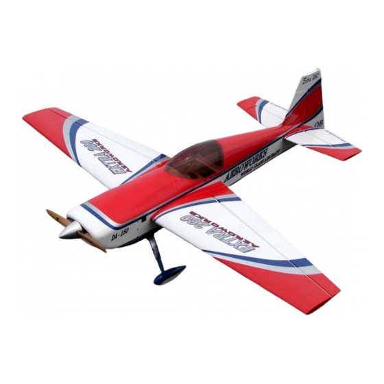
- Page 1 150cc EXTRA 260 ARF-QB (Quick Build) ASSEMBLY MANUAL AEROWORKS 401 Laredo St. Unit “D” - Aurora, CO. 80011 www.aero-works.net...
-
Page 2: Table Of Contents
TABLE OF CONTENTS Page Aeroworks Contact Information ………………………………………………………………. 3 Introduction / Warranty…………………………………………………………………………. 4 Kit Contents……………………………………………………………………………………… 5 Items Needed To Complete ……………………………………………………………………... 8 Tightening and Re-shrinking The Covering ………………………………………………….. 9 Checking Seams and Color Overlaps for Good Seal / Sealing Hinge Gaps ………..……….. 10 Applying Clear Covering to The Leading Edge of Wings and Stabs…………………………... -
Page 3: Aeroworks Contact Information
Further, Aeroworks reserves the right to change or modify this warranty without notice. In that Aeroworks has no control over the final assembly or materials used for final as- sembly, No liability shall be assumed nor accepted for any damage resulting from the use by the user of the final user-assembled product. -
Page 4: Introduction / Warranty
INTRODUCTION Your new 150cc EXTRA 260 ARF-QB is a highly aerobatic airplane. It is capable of both precision and 3-D maneuvers. The aircraft builds easily, quickly, and precisely due to its state of the art CAD design, LASER cut technology, and high quality included hardware. -
Page 5: Kit Contents
KIT CONTENTS (1) Tinted Canopy—glued on the canopy base and 150cc EXTRA 260 ARF-QB painted (4) #6 bonded washers for the mounting of the Basic Aircraft Parts: canopy base Fuselage - vertical fin installed – covered, engine (4) 3mm split lock washers for the mounting of the box &... - Page 6 Horizontal Stabilizer with elevator assembly—covered (4) #8 bonded washer for wing mounting (12) six per elevator, pin point hinges (glued) - (4) 4mm split ring lock washers for wing mounting Ready to fly (4) 4-40x16mm Hex style head bolts for stab mounting Elevators Pre-drilled for the mounting of the (4) #6 bonded washer for stab mounting control horns...
- Page 7 #10: Ultracote™ (1) 600x300mm Midnight Blue #885 - Small repairs (1) 300x300mm True Red #866- Small repairs (1) 300x300mm White #870 - Small repairs (1) 300x300mm Silver #881 - Small repairs (1) 600x300mm Transparent covering -Sealing hinge gaps (2) 2500x20mm Transparent covering strip – Sealing wing and stab leading edges #11: (24) 6.35mm machined aluminum engine stand...
-
Page 8: Items Needed To Complete
ITEMS NEEDED TO COMPLETE Hardware: • Allen wrenches US and Metric. • Dremel cutting disc and sanding drum tool • Electric drill and selection of bits • Flat head screwdriver • Hobby heat gun • Hobby iron with protective sock •... -
Page 9: Tightening And Re-Shrinking The Covering
TIGHTENING AND RE-SHRINKING THE COVERING 1. Open your kit slowly and take care not to dam- 3. If bubbles persist, use a small pin to punch holes age any parts of the kit. Remove all parts from in the bubble to relieve trapped air and reheat. their plastic protective covers for inspection. -
Page 10: Checking Seams And Color Overlaps For Good Seal Sealing Hinge Gaps
It is the responsibility of the purchaser / operator to check the covering seams and overlaps for security and a good seal. Aeroworks is not responsible for failure of covering seams or overlaps during flight. Note: If covering continues to lift apply a small amount of thin CA underneath the covering. -
Page 11: Applying Clear Covering To The Leading Edge Of Wings And Stabs
APPLYING CLEAR COVERING TO THE LEADING EDGE OF WINGS AND STABS In order to complete this step you will need: 3. Seal the top and bottom of the leading edge carefully to insure the covering is securely Clear covering, Covering Iron, Scissors, attached to the wood underneath. - Page 12 5. Cut the covering even with the wing tip being 7. Remove the clear backing from the covering. careful not to cut it to short. Note: Do not skip this step. There is a backing to the covering. Take time to remove this backing to get the correct adhesion to the already applied covering.
- Page 13 IMPORTANT It is the users responsibility to check the covering seams and overlaps for security and a good seal. Aeroworks is not responsible for failure of covering seams or overlaps during flight. This is a never ending process that must be done after each flying secession.
-
Page 14: Wing Assembly
WING ASSEMBLY Aileron Servo Installation 1. The ailerons have been pre-hinged and glued to Attach the 36” extension to the outboard servo the wing panels and are ready for flight. No lead and secure with safety wire, string, tape, other steps are necessary for hinging. Clear or other method. - Page 15 Fasten the pull string from the outboard servo Draw the 36” servo extension of the outboard hole to the male connector of the servo exten- servo through the wing and pull through the sion. wing root rib as shown. Secure with tape so that the string pulls from Repeat this process for the middle servo using the 24”...
- Page 16 Plug the male ends of the 24” and 36” exten- Install all three servos in servo wells with the sion into the female ends of one Y harness. output shaft toward the leading edge of the Next plug the male end of this Y harness into wing.
- Page 17 Assemble three pushrod and control horn Repeat mounting steps for other servos so that assemblies as shown. The ball link goes all three aileron servos are mounted in bottom between the left and right sides of the control of wing as shown. horn sides and is secured with a nylon lock nut.
- Page 18 4. Install the servo arms facing toward the wing tip 6. Use thick CA on each screw prior to as shown. installing to lock screws in place Note: CA glues have a fast drying time. Remember to work quickly. Align the left and right sides of the control 5.
- Page 19 Plug the servos into the receiver and turn on. Wrap masking tape around carbon tube for Ensure servos are centered and the servo arms marking the cut location. are parallel to the aileron hinge line. Adjust the length of the pushrods so that the aileron is at the neutral position when the servo arms are parallel to the aileron hinge line.
- Page 20 4. Using a Dremel cut off wheel cut the carbon 6. Remove the 4-40 ball link and lock nut from the tube to correct length. pushrod. Note: Seal ends of carbon tube with thin CA to Note: Make sure lock nut against servo arm ball help prevent ends from splitting.
- Page 21 Final pushrod assembly shown below. Repeat all the above steps for installing the aileron servos into the other wing panel.
-
Page 22: Stab And Elevator Assembly
STAB AND ELEVATOR ASSEMBLY Mark locations of servo mounting holes. Use Elevator Servo Installation a 1/16 bit to drill servo mounting holes. The elevators have been pre-hinged and glued to the stabs and are ready for flight. No other steps are necessary for hinging. Clear cover- ing has been provided for sealing of the hinge gaps if desired. - Page 23 Plug the elevator servo leads into the female Gather the elevator control linkage parts as ends of the 11” Y harness as shown. shown below. There are (2) pushrods, (4) ball link assemblies, (2) brass spacers, (2) left and (2) right side control horns, and (12) wood screws per stab and elevator.
- Page 24 You may mount the ball links into any of the Align the control horns over the factory drilled three control horn holes. However, it is very holes. important that you use the same hole for each control horn. We recommend you use the middle or bottom hole to achieve desired 3D throws and top hole if you prefer more precision or I.M.A.C.
- Page 25 Align the left and right sides of the control Carbon Reinforcement Tube horns to the mounting holes and mount using six wood screws as shown. Installation Gather the supplied carbon tube for reinforcing the elevator pushrods. Plug the Y harness into the female end of the 48”...
- Page 26 Mark cut location onto carbon tube. Carbon 5. Remove the 4-40 ball link from the control horn. tube should fit between 4-40 ball link lock nuts. Note: Make sure lock nuts are tight so pushrod length does not change. 6. Remove the 4-40 ball link and lock nut from the 4.
- Page 27 7. Slide carbon reinforcing tube over the 4-40 pushrod and reassemble ball link to pushrod end. Note: Make sure lock nut against servo arm ball link is tight so pushrod length will not change. Final pushrod assembly shown below. Repeat the all the above steps for installing the elevator servos into the other stab.
-
Page 28: Rudder, Rudder Servos And Tail Wheel Assembly
RUDDER , RUDDER SERVOS AND TAILWHEEL ASSEMBLY Mix epoxy in mixing cup and use a tapered Rudder Installation stick to apply the epoxy inside the pre-drilled holes in the trailing edge of the fin. Apply Gather the rudder, hinges, epoxy, Vaseline, epoxy to one side of each hinge and insert the stir sticks, mixing cup and alcohol as shown. -
Page 29: Rudder Servos Installation
Mix epoxy in mixing cup and use a tapered Ensure there is minimal to no gap between fin stick to apply the epoxy inside the pre-drilled and rudder. Allow epoxy to fully cure. holes in the leading edge of the rudder. Apply epoxy onto each hinge. - Page 30 Attach the Y harness to aft rudder servo leads Install the forward rudder servo with the out- and secure with safety wire, string, tape, or put shaft forward. other method. Ensure the connectors will not come apart from vibration or light tension. Install the aft rudder servo with the output Mark and use a 1/16 bit to drill the rudder shaft forward.
- Page 31 Install rudder servos with servo screws. Thread the threaded rods into the ball link as shown. Slide the carbon sleeve over the threaded rod Rudder Servo Arm Coupler as shown. 1. Gather the rudder servo arm coupler hardware as shown below. There are (4) 4-40 ball links with hardware, (2) 4-40 all thread rods, and (2) car- bon sleeves Note: Rudder coupler hardware is Not Supplied.
- Page 32 Screw the remaining ball link onto the Install the rudder servo output arms on the rud- threaded rod as shown. Repeat above steps der servos as shown. Adjust the length of the for the remaining rudder arm coupler rod. rudder coupler rods so that the rudder output arms are at the centered position.
- Page 33 Feed the rudder cable through the pre installed Insert rudder cable through the brass swage cable exit tube in the tail of the fuse toward the tube, then through the threaded coupler hole, front. Repeat on other side. and back through the brass swage tube as shown.
- Page 34 Tighten the second loop through the brass Attach a 4-40 ball link to each threaded cou- swage tube and crimp the brass tube with a pler. crimping tool or pliers. Cut off excess cable as shown. Repeat above steps for the other side rudder cable.
- Page 35 Connect rudder servo output arms and rudder Align the control horns over the factory drilled cables as shown below. holes. Rudder Control Horn Installation Use thick CA on each screw prior to installing to lock screws in place Gather the rudder control horn parts as shown below.
- Page 36 Align the left and right sides of the control Screw threaded coupler halfway into ball link horns to the mounting holes and mount using and reinstall the ball link onto the rudder con- six wood screws as shown. trol horn with the 4-40 bolt and locknut. Remove the ball link from the rudder control Plug the rudder servo Y harness into the rud- horn.
- Page 37 Tape the rudder balance tab to the top leading Loop the cable back through the brass swage edge of the vertical fin in the neutral position tube as shown. as shown. This ensures the rudder is straight when the cables are attached. Slide brass swage onto rudder cable.
- Page 38 Crimp the brass tube with a crimping tool or Cut off excess cable as shown. pliers. Hint: If additional crimping is needed a small A drop of thin CA may be applied to the C-Clamp may be used for additional crimping swage tube to help secure the cable.
-
Page 39: Tail Wheel Installation
Re-attach the ball link and cable to the rudder Tail Wheel Installation control horn as necessary. 1. Gather the tail wheel parts shown below. Carbon Tail wheel strut, 3 tail wheel mounting Repeat above steps for opposite side rudder screws, aluminum steering tiller, 2 tiller mount- cable. - Page 40 Mount the tail wheel steering tiller using two Mount the tail wheel strut using three wood wood screws. screws. Place a drop of thick CA on tail wheel strut Attach the steering spring to one side of the mounting screws before inserting in the pre- rudder tiller.
- Page 41 Use pliers to twist spring ends closed around Use pliers to twist spring ends closed around the rudder tiller. the tail wheel tiller. Slightly stretch the spring and insert through Cut off excess spring wire as shown. the tail wheel tiller. Repeat for opposite side tail wheel spring.
- Page 42 Tail wheel final assembly is complete.
-
Page 43: Main Landing Gear, Gear Cuff And Wheel Pant Assembly
MAIN LANDING GEAR, GEAR CUFF AND WHEEL PANT ASSEMBLY Remove the landing gear cover by removing Main Landing Gear Installation the two bolts on the bottom of the cover. Gather the landing gear parts as shown below. (1) landing gear strut, (2) strut cuffs, (2) wheels, (2) axle assemblies, (2) wheel pants and landing gear mounting hardware. - Page 44 Note that the trailing edge of the landing gear Bolt landing gear strut to fuse with (4) bolts strut is tapered. The tapered edge goes toward and washers. Ensure tapered edge of the gear the rear of the fuse. strut is facing toward the rear. Assemble the landing gear bolts with lock Reinstall the landing gear cover.
- Page 45 Use a drop of blue Loctite on the landing gear Gather the landing gear cuffs, mounting bolt, cover bolts before attaching the cover. flat washers, and lock washers. Note: There is a right and left gear cuff. Reinstall both landing gear cover bolts with Slide the gear cuff onto the proper gear strut.
- Page 46 Landing gear cuff installed on the correct side Slide the lock washer then the flat washer on and fitting correctly to fuse. the cuff mounting bolt. Use a drop of blue Loctite on each bolt before installing the bolt. Landing gear cuff on wrong side showing Install left and right gear cuffs as shown.
- Page 47 Final gear assembly with cuff installed. 2. Install the axle into the gear strut with nylon lock nut. Optional: Use a drop of blue Loctite on the wheel axle bolt before assembly. Wheels and Wheel Pants Installation Use two wrenches to screw the lock nut on the wheel axle.
- Page 48 Align the flat sides of the axle bolt vertical and Now tighten the axle nut against the landing snug the lock nut against the landing gear gear strut with a small wrench while using the strut. Do not tighten securely yet. Then align wheel pant slot to hold the flat sides of the the wheel pant slot over the axle bolt as shown axle bolt in alignment.
- Page 49 Remove the wheel pant from the landing gear Install the inner wheel collar on the axle. Use strut. a drop of blue Loctite on the wheel collar set screw and tighten the wheel collar in place. 9. Use two wrenches to permanently tighten the Install the wheel and outer wheel collar.
- Page 50 Slide the lock washer then the flat washer on Repeat above steps for other wheel and wheel the wheel pant mounting bolts. Use blue pant. Loctite on the bolts before final tightening. Final installation of wheel pant with two mounting bolts.
-
Page 51: Engine, Muffler Or Canister And Throttle Servo Installation
ENGINE, MUFFLER OR CANISTER AND THROTTLE INSTALLATION Line up the template with the pre-marked Engine Installation firewall thrust lines. Mark the location of the engine mounting holes. 1. The 150cc Extra 260 will accept a wide range of engine types. Illustrations for a DA-150 installation are provided below. - Page 52 Use a 1/4 drill bit to drill the engine mounting Machined (6mm) aluminum spacers are in- holes. cluded to set the proper stand off distance for the engine used. Remove the 4 screws from the top of the en- Use (2) aluminum spacers behind the DA-150 gine box cover and remove the engine box top to ensure adequate standoff from firewall.
- Page 53 The required distance from the front of the Tighten firmly. Use Loctite to secure. firewall to the front of the prop mount on the 8 1/4” engine is as shown below. Insert the (4) bolts through the engine mount, Throttle Servo Installation spacers and washers.
- Page 54 2. Locate the supplied servo mounting trays, push- If standard style muffler cans are to be used, rods, ball links, threaded coupler and hardware install the standard muffler cans to the engine as shown below. cylinder heads as shown. Attach the throttle pushrod to the engine throttle arm as shown.
- Page 55 Use a rotary cutting tool to cut out the throttle Mark and use a 1/16” drill bit for the servo servo mounting hole. mounting screws. Note: Cover engine with a towel or cloth or use masking tape to protect from any debris getting into the carburetor or cylinders.
- Page 56 Thread a 4-40 ball link half way onto the Cut the throttle pushrod to the proper length. threaded coupler as shown. With the servo arm centered and the throttle Gather the soldering tools as shown below. arm of the carburetor at half throttle, measure and mark the end of the throttle pushrod wire Note: For best results we recommend a high that will be inserted into the threaded coupler...
- Page 57 A none soldering method of attaching throttle Solder the threaded coupler to the throttle pushrod is shown in the following steps. pushrod wire. Hardware for this method is not supplied. Note: Lightly sand end of rod for best bond. Gather (2) 4-40 ball links, (1) brass spacer, 4-40 all thread, and carbon tube.
- Page 58 18. Cut 4-40 rod and carbon rod to correct length Place the bottom engine box cover over the Slip the carbon rod over the 4-40 threaded pushrod and mark the location of the throttle pushrod. pushrod exit on the cover. Install the throttle pushrod to the engine Use a rotary cutting tool or hobby saw to cut throttle arm as shown.
-
Page 59: Standard Muffler Installation
Dry fit the engine box bottom cover to ensure Place a drop of CA glue on the throttle servo there is no binding of the pushrod from full mounting screws from inside the engine box to closed to full open throttle position. Trim the prevent loosening from engine vibration. -
Page 60: Canister Muffler Installation
Use a drop of blue Loctite on muffler bolts Side view of standard muffler installation. before installation. Install muffler cans using the supplied gasket Canister Muffler Installation or high temp silicon gasket material and 1. Gather the header and canister parts as shown: securely bolt to cylinder heads as shown. - Page 61 Covering removed from two air exit holes just If using standard mufflers, skip the Note: aft of the landing gear. following steps and go to fuel tank installation. Page #70 Use a sealing iron to ensure the covering is bonded to the bottom of the fuse frame around the pre cut air exit holes.
- Page 62 Covering removed from the air exit holes and Dry fit the larger aft tunnel balsa floor baffle bottom fuse bay for canister installation. and trim as necessary. Apply medium CA glue to baffle and install. Gather the included pre cut balsa canister tun- Install the aft tunnel balsa floor baffle as nel baffles, lite-ply canister mounts, and sili- shown.
- Page 63 Dry fit the smaller front tunnel balsa floor Gather the two supplied silicon tubes for baffle for proper fit. Apply medium CA glue making the vibration isolation mounts. to baffle and install. Mark eight 7/8” pieces onto each tube. Note: The silicon tubing may have already been pre-cut for you, if so skip this step.
- Page 64 Insert the pieces of silicon tubing into the Ensure the aft canister mounting former is plywood cutouts in the pre-cut canister flush with the inside fuse sides as shown. mounting formers. Apply CA glue to all edges to secure former in place.
- Page 65 Front canister mounting former in place. Insert canisters from rear through the canister mounting formers. Ensure both canister mounting formers are Rotate canisters as necessary to get the stinger flush with the inside of the fuse sides as exhaust pipes through the rear former and out shown.
- Page 66 Slightly lift the center brace between the air Slip the Teflon couplers onto the drop headers exit holes to clear the stinger exhaust pipes and place the spring clamps on the Teflon cou- when rotating the canister to the proper plers.
- Page 67 Rotate the headers for proper alignment to the Firmly tighten the header mounting screws to exhaust ports on the cylinders as shown. the engine. Install the header pipes to the engine using Proper alignment of canisters and headers blue Loctite as shown. from bottom view.
- Page 68 Proper alignment of canisters and headers Dry fit both sides of the aft canister tunnel from rear view. baffle to fit behind the former just aft of the canisters. Proper alignment of canisters and headers Apply CA glue to each half of the aft tunnel from front view.
- Page 69 Both halves of the aft rear tunnel baffle glued Final installation of canister mufflers and in place behind the former. headers from bottom view. Use supplied covering material to recover the access hole in the bottom of the fuse as shown.
-
Page 70: Fuel Tank Assembly And Installation
This will keep the weight of the fuel clunk from pulling the fuel line off the Note: The fuel “T” and fuel filler dot are not brass tube. supplied, but are available through Aeroworks. (Barbs are Supplied) - Page 71 2. If you have sheeted the underside of the tank Cinch the nylon ties securely to hold the tank floor for the canister tunnel, place the fuel tank against the foam on the fuel tank floor. on the tank floor and mark the position of the nylon ties for mounting the tank.
- Page 72 Install the fuel tubing as shown securing with 8. Mark and drill the fuel vent exit hole on the bot- small nylon ties. You will need an after tom of the fuse. Cut off excess fuel line as market fuel “T” and fuel filling dot. shown.
- Page 73 Connect the fuel line to the engine carburetor intake nipple and secure with small nylon tie.
-
Page 74: Ignition Module And Radio Installation
IGNITION AND RADIO INSTALLATION Gather the supplied mounting hardware to be Position the ignition module inside the engine used. Included in the kit are large and small box to allow both of the spark plug leads to nylon ties, One Wrap Velcro strips, and foam exit and properly connect to the engine without rubber pads as shown, excess tension or chafing. - Page 75 Use a 1/4” drill bit to drill the nylon tie Install the ignition module and the foam pad mounting holes as shown. with a nylon tie as shown. Roll the supplied foam rubber to make a Secure the ignition timing connectors with 4 layer pad as shown.
- Page 76 Use thick CA glue on the engine box hatch Switch Installation screws prior to installing. Gather the switches to be mounted as shown below. We used one switch for the ignition, and one switch for each receiver. Install the engine box hatch screws as shown. Fit the wing to the fuselage and check that switch location will not interfere with the mounting of the wing.
- Page 77 We chose to mount the ignition switch below Mark the location of the wing leading edge on the one radio switch on the left side. Mark the the fuse to avoid conflict with the switch location for ignition and radio switches using mounting location.
- Page 78 Mount switches in accordance with the switch Ignition Battery and Regulator manufacturers instructions and hardware. Gather the ignition battery and regulator if used as shown. Radio and ignition switches mounted on the Roll the supplied foam rubber to make a 4 left side.
- Page 79 Insert the Velcro tie wraps under the fuse floor Trim excess Velcro tie wrap as shown. for mounting ignition battery as shown. Wrap the Velcro tie wraps around the ignition Ignition battery secure to fuse. battery and foam pad and secure to fuse floor as shown.
-
Page 80: Radio Installation
Secure the battery connectors with safety wire, Radio Installation string, tape, or other method. Ensure the con- nectors will not come apart from vibration or Gather the receivers, batteries, and regulators light tension. as shown below. A typical ignition installation shown below. Mount the receivers, batteries, and regulators Secure the regulator to the fuse floor using as shown below using the same steps and... - Page 81 Apply baby powder or corn starch to antenna Tape the remaining receiver antenna wire to wire to assist getting it into the guide tube. the radio mounting tray as shown. This will prevent the antenna wire from vibrating back out. Tape the receiver antenna wire to the end of Attach all servos, battery, regulator, and the antenna guide tube as shown.
-
Page 82: Cowl Installation
Always check the operating temperature of want to add additional baffling to custom fit to your engine to prevent any damage from your engine. occurring. Aeroworks is not responsible for damages incurred from improper engine cooling. Cowl Preparation For Additional balsa sheeting may be added to the... - Page 83 Apply clear tape to the edge of the folder Mark the center of the blind nut in the lower template as shown. cowl mounting tabs from the top down with a T-pin. Tape the template to the bottom of the fuse Remove the template.
- Page 84 Lift the template so that it contacts the bottom Insert two cowl mounting bolts with rubber of the muffler exhaust stacks. Trace the backed washers through the template from the location of the exhaust stack exit holes. bottom up. Mount the template to the bottom of the cowl Exhaust stack holes traced onto the template.
- Page 85 Use a hobby knife to cut out the exhaust stack Remove the template. Extend holes towards holes in template. fuse former by drawing a 2 1/2” long hole. This will allow the cowling to slip over the stacks. Allow a 1/4” clearance around the outside edge Trial fit the template until the proper size holes of the exhaust stack tubes.
- Page 86 Exhaust stack holes cut into bottom of the Mount the template to the bottom of the cowl cowl. as shown. Mark the cutout locations onto the cowl as shown. Note: Take care and test painted areas prior to using any type of paint remover, rubbing alcohols or cleaners to remove any pen lines.
- Page 87 Mark the hot air exit hole using the template. Remove template and draw a hot air exit hole. This hole should be a minimum of four times the size of the air inlet holes at the front of the Note: Take care and test painted areas prior to cowling.
- Page 88 Always check the operating temperature of your engine to prevent any damage from occurring. Aeroworks is not responsible for damages incurred from improper engine cooling.
-
Page 89: Manual Choke Installation
Use a rotary cutting tool, files, and sandpaper Manual Choke Pushrod Installation to cut out and smooth the edges of the cooling openings in the bottom of the cowl as shown. Gather the choke pushrod and ball link shown below. Note: Take care not to cut or scratch the cowl. - Page 90 Use a hobby knife or small drill to drill the Make a 90º bend at the end of the choke exit hole for the choke pushrod as shown. pushrod as shown. Measure the length of the choke pushrod Reattach the lower cowl with the choke push- required to extend out of the front of the cowl rod extending through the hole.
-
Page 91: Final Cowl Assembly
Final Cowl Assembly Use a drop of blue Loctite on each cowl screw prior to assembly. Firmly tighten each cowl screw through the top and bottom of the cowl and to the fuse as shown. -
Page 92: Preflight Preparation
PRE-FLIGHT PREPARATION 1. Gather the (4) 8-32 wing mounting bolts, (4) #8 Gather the (4) 4-40 stab mounting bolts and large rubber backed washers and (4) hair pins. (4) #6 small rubber backed washers. Note: Always check wing attachment bolts are securely tightened. - Page 93 5. Gather the (8) 4-40 cowl mounting bolts and 7. Gather the (4) 4-40 hatch mounting bolts and (8) #6 small rubber backed washers. (4) #6 small rubber backed washers. Note: It is highly recommended you apply thin CA glue to the front hold down dowels. This is a High vibration area and can loosen the front dowels.
-
Page 94: Decal Installation
DECAL INSTALLATION 3. Factory placement of decals. 1. Decals supplied with the kit may vary from the photos below. Decal application steps will be similar. Gather supplied decals, transfer tape, ruler, scis- sors, hobby knife, plastic squeegee or credit card, Windex or Application fluid like Rapid Tac. - Page 95 4. Factory placement of decals shown.
- Page 96 Remove backing from Clear transfer tape. 5. Cut transfer tape to accommodate decal size. Apply clear transfer tape over top of decal. Note: Transfer tape will be reused. DO NOT throw away any transfer tape until decal placement is complete. Decals supplied with the kit may vary from the photos below.
- Page 97 8. Press transfer tape to top of decal. Spray model surface with application fluid, Windex or soapy water solution. Peel backing from decal. Spray back side of decal with application fluid, Windex or soapy water solution.
- Page 98 Position decal in proper location. Applica- Pull transfer tape from top of decal. Take tion fluid will allow decal to be moved slightly. care not to pull away or damage decal. Using a plastic squeegee or credit card. Spread Let decal dry before applying top decal. decal smooth and remove all excess application fluid.
- Page 99 16. Repeat installation process of bottom decal for Pull transfer tape from top of decal. Take top decal installation. Use application fluid for care not to pull away or damage decal. easier installation Finished decal installation. Work slowly 17. Place top decal over bottom decal. Position evenly and carefully and you will be rewarded and centered on bottom decal.
-
Page 100: Center Of Gravity / Control Throws
CENTER OF GRAVITY - CONTROL THROWS Start at recommended CG until you are com- Center of Gravity fortable with the flight characteristics of the Warning, DO NOT skip this step! aircraft. You may find this a bit nose heavy at first but that is fine to start with. - Page 101 Elevator throw measured in inches at the Use the supplied flight control deflection me- widest point of the elevator . It is ter to measure the throws in degrees recommended you level the model as shown. Rudder throw measured in inches from the Elevator throw measured in degrees.
-
Page 102: Control Throw Deflection Table
Aileron throw measured in degrees at widest Control Throw Deflection Table point of the aileron. Low Rate High Rate Aileron 2 1/2” or 20˚ up 3 7/8” or 30˚ up 2 1/2” or 20˚ down 3 7/8” or 30˚ down Rudder 2”... -
Page 103: Preflight Check List
Preflight Check List Range check: Do a range check with and without Center of Gravity: Check CG is set properly. the engine running in accordance with the radio manufacturer instructions. If there is insuffi- Engine: The engine should run smoothly at all cient range or a large reduction with the engine throttle settings with smooth transition from running, do not fly until it is resolved! - Page 104 Spins upright and inverted • Flat Spins upright and inverted • Harriers upright and inverted • Water falls • Torque Rolls • Rolling circles • Rolling harrier The sky and your imagination are you only limits. FLY and ENJOY! AEROWORKS World Class Aircraft...
- Page 105 Extra 260 CUSTOMER NOTES ___________________________________________________________________________ ___________________________________________________________________________ ___________________________________________________________________________ ___________________________________________________________________________ ___________________________________________________________________________ ___________________________________________________________________________ ___________________________________________________________________________ ___________________________________________________________________________ ___________________________________________________________________________ ___________________________________________________________________________ ___________________________________________________________________________ ___________________________________________________________________________ ___________________________________________________________________________ ___________________________________________________________________________ ___________________________________________________________________________ ___________________________________________________________________________ ___________________________________________________________________________ ___________________________________________________________________________ ___________________________________________________________________________ ___________________________________________________________________________ __________________________________________________________________________...
Need help?
Do you have a question about the EXTRA 260 ARF-QB and is the answer not in the manual?
Questions and answers