
Related Manuals for AeroWorks YAK 54 ARF-QB


Summary of Contents for AeroWorks YAK 54 ARF-QB
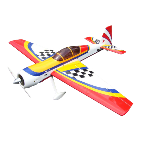
- Page 1 150cc YAK 54 ARF-QB (Quick Build) ASSEMBLY MANUAL AEROWORKS 401 Laredo St. Unit “D” - Aurora, CO. 80011 www.aero-works.net...
-
Page 2: Table Of Contents
TABLE OF CONTENTS Page Aeroworks Contact Information …………………………………………………………………………. 3 Introduction / Warranty…………………………………………………………………………. ………. 4 Kit Contents………………………………………………………………………………………………… 5 Items Needed To Complete ……………………………………………………………………………….. 8 Tightening and Re-shrinking The Covering ……………………………………………………………… 9 Checking Seams and Color Overlaps for Good Seal / Sealing Hinge Gaps ………..………………….. 10 Wing Assembly………………………………………………………………….…………………………. -
Page 3: Aeroworks Contact Information
E-mail: Info@aero-works.net Thank you for choosing the Aeroworks 150cc Yak 54 ARF-QB. We put great effort into making this plane the best model you will ever build and fly. We have provided you with the highest quality kit and performance possible. We wish you great success in the assembly and flying of your new Aeroworks 150cc Yak 54 ARF-QB. -
Page 4: Introduction / Warranty
LIMITED WARRANTY READ! It is important to notify Aeroworks of any damage or problems with the model within 30 days of receiving your airplane to be covered under warranty. If you wish to return this air- craft for any reason a 15% restock fee will be charged to the customer. In addition the cus- tomer is responsible for all return shipping cost and all prior shipping cost will not be re- funded. -
Page 5: Kit Contents
KIT CONTENTS (1) Canopy base-painted, installed on the fuselage by 150cc Yak 54 ARF-QB (4) 4-40 blind nuts and (4) 4-40x16mm hex style bolts Basic Aircraft Parts: (1) Tinted Canopy—glued on the canopy base and Fuselage - vertical fin installed –... - Page 6 (2) Aluminum anti-rotation dowels - installed pre- (1) 16mm O.D. x 460mm Carbon stab tube - Rear drilled hole for cotter pin installation (4) 8-32 x 30mm Hex head bolts for wing mounting (11) pin point hinges installed (glued) Read to fly (4) #8 bonded washer for wing mounting (2) Aileron servo pull strings installed (4) 4mm split ring lock washers for wing mounting...
- Page 7 (1) 180x120x6 mm foam - Fuel tank (1) 160x 100x6mm foam - Smoke tank (3) 300x80x8mm foam - Receiver and battery (8) 8x450mm Nylon ties - fuel line (10) 3x150mm Nylon ties - fuel tank (6) 356x12.5 Velcro one wrap strap - Receiver and battery #10: Ultracote™...
-
Page 8: Items Needed To Complete
ITEMS NEEDED TO COMPLETE Hardware: • Allen wrenches US and Metric. • Dremel cutting disc and sanding drum tool • Electric drill and selection of bits • Flat head screwdriver • Hobby heat gun • Hobby iron with protective sock •... -
Page 9: Tightening And Re-Shrinking The Covering
TIGHTENING AND RE-SHRINKING THE COVERING 1. Open your kit slowly and take care not to dam- 3. If bubbles persist, use a small pin to punch holes age any parts of the kit. Remove all parts from in the bubble to relieve trapped air and reheat. their plastic protective covers for inspection. -
Page 10: Checking Seams And Color Overlaps For Good Seal Sealing Hinge Gaps
It is the responsibility of the purchaser / operator to check the covering seams and overlaps for security and a good seal. Aeroworks is not responsible for failure of covering seams or overlaps during flight. Note: If covering continues to lift apply a small amount of thin CA underneath the covering. -
Page 11: Wing Assembly
WING ASSEMBLY Aileron Servo Installation 1. The ailerons have been pre-hinged and glued to 3. Attach the 36” extension to the outboard servo the wing panels and are ready for flight. No lead and the 24” extension to the middle servo other steps are necessary for hinging. - Page 12 Secure with tape so that the string pulls from Attach a Y harness to the inboard servo as shown below. to assist in the front end of the connector drawing the servo wire through the wing without hanging up inside the wing. Pull both servo leads through the root end of Pull Y harness through root end of wing.
- Page 13 Plug the male ends of the 24” and 36” exten- Install all three servos in servo wells with the sion into the female ends of one Y harness. output shaft toward the leading edge of the Next plug the male end of this Y harness into wing.
- Page 14 Assemble three pushrod and control horn Repeat mounting steps for other servos so that assemblies as shown. The ball link goes all three aileron servos are mounted in bottom between the left and right sides of the control of wing as shown. horn sides and is secured with a nylon lock nut.
- Page 15 4. Install the servo arms facing toward the wing tip 6. Use thick CA on each screw prior to as shown. installing to lock screws in place Note: CA glues have a fast drying time. Remember to work quickly. Align the left and right sides of the control 5.
- Page 16 Plug the servos into the receiver and turn on. Wrap masking tape around carbon tube for Ensure servos are centered and the servo arms marking the cut location. are parallel to the aileron hinge line. Adjust the length of the pushrods so that the aileron is at the neutral position when the servo arms are parallel to the aileron hinge line.
- Page 17 4. Using a Dremel cut off wheel cut the carbon 6. Remove the 4-40 ball link and lock nut from the tube to correct length. pushrod. Note: Seal ends of carbon tube with thin CA to Note: Make sure lock nut against servo arm ball help prevent ends from splitting.
- Page 18 Final pushrod assembly shown below. Repeat all the above steps for installing the aileron servos into the other wing panel.
-
Page 19: Stab And Elevator Assembly
STAB AND ELEVATOR ASSEMBLY 3. Mark locations of servo mounting holes. Use a Elevator Servo Installation 1/16 bit to drill servo mounting holes. 1. The elevators have been pre-hinged and glued to the stabs and are ready for flight. No other steps are necessary for hinging. - Page 20 5. Plug the elevator servo leads into the female 7. Gather the elevator control linkage parts as ends of the 11” Y harness as shown. shown below. There are (2) pushrods, (4) 4-40 ball link assemblies, (2) flat washers (not pic- tured) (2) brass spacers, (2) left and (2) right side control horns, and (12) wood screws per stab and elevator.
- Page 21 You may mount the ball links into any of the 11. Align the control horns over the factory drilled three control horn holes. However, it is very holes. important that you use the same hole for each control horn. We recommend you use Note: Control horns have been set at a slight the middle or bottom hole to achieve desired offset to allow for maximum torque at full...
- Page 22 16. Use the provided draw strings in fuselage and Mount control horn using six wood screws as pull elevator extension wires through the wire shown. holders in the fuse. 14. Completed stab and elevator shown. Repeat steps for other stab and elevator. 17.
- Page 23 3. Mark cut location onto carbon tube. Carbon tube Carbon Reinforcement Tube should fit between 4-40 ball link lock nuts. Installation Note: Make sure lock nuts are tight so pushrod length does not change. 1. Gather the supplied carbon tube for reinforcing the elevator pushrods.
- Page 24 7. Slide carbon reinforcing tube over the 4-40 push- 5. Remove the 4-40 ball link from the control horn. rod and reassemble ball link to pushrod end. 6. Remove the 4-40 ball link and lock nut from the Final pushrod assembly shown below. pushrod.
-
Page 25: Rudder And Rudder Servos Installation
RUDDER AND RUDDER SERVOS INSTALLATION Mix epoxy in mixing cup and use a tapered Rudder Installation stick to apply the epoxy inside the pre-drilled holes in the trailing edge of the fin. Apply Gather the rudder, hinges, epoxy, Vaseline, epoxy to one side of each hinge and insert the stir sticks, mixing cup and alcohol as shown. - Page 26 Mix epoxy in mixing cup and use a tapered Ensure there is minimal to no gap between fin stick to apply the epoxy inside the pre-drilled and rudder. Allow epoxy to fully cure. holes in the leading edge of the rudder. Apply epoxy onto each hinge.
- Page 27 2. Assemble the ball links between the control 4. Use thick CA on each screw prior to installing to horns as shown. Secure with nylon lock nut. lock screws in place Note: Mount ball link to bottom control horn hole Note: CA glues have a fast drying time.
- Page 28 6. Gather the rudder servos (min 180 in./oz.) 8. Remove radio floor from fuselage. 3” to 3 1/2” Double out put servo arms and a 11” Y harness as shown below. Note: If using higher Torque (min 300 in./oz.) Digital, Metal Geared servo, only two servos are required.
- Page 29 10. Install the aft rudder servo with the output shaft 12. Install rudder servos with servo mounting forward. Pull the servo lead and Y harness up screws. through the forward servo cutout. Attach the Y harness to the forward rudder servo lead and secure with safety wire, string, tape, or other method.
- Page 30 14. Tie off or tape rudder cables to keep them from 16. Insert rudder cable through the brass swage tube pulling into fuse. as shown. 15. Pull the rudder cables from the fuse tail to the 17. Thread cable through the threaded coupler hole, rudder servo tray.
- Page 31 18. Loop the cable back through the brass swage 20. Cut off excess cable as shown. tube and pull tight as shown. 19. Crimp the brass tube with a crimping tool or pli- 21. A drop of thin CA may be applied to the swage ers.
- Page 32 22. Thread a 4-40 ball link half way onto the 25. Tape the rudder balance tab to the top leading threaded coupler. edge of the vertical fin in the neutral position as shown. This ensures the rudder is straight when the cables are attached.
- Page 33 27. Remove ball link from rudder control horn 29. Reinstall the ball link onto the rudder control horn. Note: Do not secure with lock nut at this time. This will make final adjustment of cables easier shown during a later step. 28.
- Page 34 31. Loop the cable back through the brass swage 33. Crimp the brass tube with a crimping tool or pli- tube as shown. ers. 32. Pull cable until tight. Cut off excess cable as shown.
- Page 35 35. A drop of thin CA may be applied to the swage Rudder Servo Arm Coupler tube to help secure the cable. 1. Gather the rudder servo arm coupler hardware as Repeat above steps for opposite side rudder cable. shown below. There are (4) 4-40 ball links with hardware, (2) 4-40 all thread rods, (4) Brass spacers and (2) carbon sleeves Note: Rudder coupler hardware is Not Supplied.
- Page 36 3. Slide the carbon sleeve over the threaded rod as 5. Attach the two rudder coupler rods to both rud- shown. der servo double output arms using the 4-40 ball links, spacers and bolts as shown. Secure bolts with lock nuts. Note: You will want to use a minimum of 3”...
-
Page 37: Tail Wheel Installation
3. Place tail wheel steering tiller over the pre- Tail Wheel Installation drilled holes in the bottom of the rudder. 1. Tape the rudder balance tab to the top leading edge of the vertical fin in the neutral position as shown. - Page 38 5. Mount the tail wheel steering tiller using two 7. Place a drop of thick CA on tail wheel strut wood screws. mounting screws before inserting in the pre- drilled mounting holes on the bottom rear of the fuse. 6. Place tail wheel strut over the pre-drilled holes 8.
- Page 39 9. Attach the steering spring to one side of the rud- 11. Use pliers to twist spring ends closed around the der tiller. Center the spring between the rudder tail wheel tiller. Cut off excess spring wire as and tail wheel tillers. shown.
-
Page 40: Main Landing Gear And Wheel Pant Installation
MAIN LANDING GEAR AND WHEEL PANT INSTALLATION 3. Gear cover removed shown below. Repeat for Main Landing Gear Installation opposite side gear cover. 1. Gather the landing gear parts as shown below. (2) landing gear struts, (2) wheels, (2) axle as- semblies, (4) wheel collars, (2) wheel pants and landing gear mounting hardware. - Page 41 6. Assemble the landing gear bolts with lock 8. Install the axle into the gear strut with nylon washer and flat washer. Use a drop of blue Loc- lock nut. Only snug tighten at this time. tite on landing gear bolts before attaching the landing gear.
- Page 42 10. Install the inner wheel collar on the axle. Use a 12. Slide the lock washer then the flat washer on the drop of blue Loctite on the wheel collar set wheel pant mounting bolts. Use blue Loctite on screw and tighten the wheel collar in place. the bolts before final tightening.
- Page 43 14. Repeat above steps for other wheel and wheel 16. Reinstall landing gear cover bolt with Loctite pant. and fasten firmly. 15. Reinstall the landing gear cover. 17. Final gear assembly with gear cover installed shown below. Repeat installation steps for other gear cover.
-
Page 44: Engine Installation
ENGINE INSTALLATION 3. Locate the laser cut engine mounting template Engine Installation for the DA-150. 1. The 150cc Yak 54 will accept a wide range of Note: If other engines are used the templates may engine types. Illustrations for a DA-150 be modified to fit you engine selection. - Page 45 5. Remove the engine box hatch cover. 7. Use a 1/4 drill bit to drill the engine mounting holes in firewall. 6. Align mounting template with firewall and tape 8. Using the provided DA150 wooden spacer in place. mounting block. Install mounting bolts through engine mounting plate and spacer.
-
Page 46: Throttle And Choke Servo Installation
9. Test fit engine to firewall. The required distance Throttle and Choke Servo Installation from the front of the firewall to the front of the 8 5/8” 1. Gather the left and right plywood throttle and prop mount on the engine is as shown choke servo mounting trays, the throttle and below. - Page 47 3. If standard style muffler cans are to be used, in- 5. Use a rotary cutting tool to cut out the throttle stall the standard muffler cans to the engine cyl- servo mounting hole. inder heads as shown. Attach the throttle push- rod to the engine throttle arm as shown.
- Page 48 7. Mark and use a 1/16” drill bit for the servo 9. Thread a 4-40 ball link half way onto the mounting screws. threaded coupler as shown. 8. Mount the throttle servo using servo mounting 10. With the servo arm centered and the throttle arm screws.
- Page 49 11. Cut the throttle pushrod to the proper length. 13. Solder the threaded coupler to the throttle pushrod wire. Note: Lightly sand end of rod for best bond. 12. Gather the soldering tools as shown below. 14. Attach the throttle pushrod with the 4/40 ball links and secure.
- Page 50 3. Cut 4-40 rod and carbon rod to correct length 1. A none soldering method of attaching throttle Slip the carbon rod over the 4-40 threaded pushrod is shown in the following steps. pushrod. Hardware for this method is not supplied. Gather (2) 4-40 ball links, (1) brass spacer, 4-40 all thread, and carbon tube.
-
Page 51: Standard Muffler Installation
3. Install muffler cans using the supplied gasket or Standard Muffler Installation high temp silicon gasket material and securely bolt to cylinder heads as shown. 1. Gather the standard muffler parts as shown: Shown: DA150-C (Compact muffler set) Also fits: DA150 (Standard muffler set) 2. - Page 52 2. Gather the included pre cut balsa pipe tunnel 4. Use a hobby knife to remove the covering from sheeting, lite-ply pipe mounting brackets, pre cut the pipe tunnel pre cut air exit holes. silicone tubing and mounting hardware as shown below.
- Page 53 6. Remove tunnel hatch cover from fuse bottom. 8. Front tunnel sheeting installed shown below. 7. Dry fit the pre cut front tunnel balsa floor sheet- 9. Dry fit the pre cut rear tunnel balsa floor sheet- ing and trim as necessary. Apply medium CA ing and trim as necessary.
- Page 54 10. Rear tunnel sheeting installed shown below. 12. Mount front bracket to former with 4-40 mount- ing bolts, flat washers and lock washers. Apply blue Loctite to mounting bolts. 11. Insert the pre-cut pieces of silicon tubing into the 13. Securely tighten front mounting bracket to rear plywood cutouts in the pipe mounting formers.
- Page 55 14. Remove mounting screws and radio floor from 16. Mount rear bracket to former with 4-40 mount- fuselage. ing bolts, flat washers and lock washers. Apply blue Loctite to mounting bolts. 15. Slide rear mounting bracket into position next to 17.
- Page 56 20. Assemble the pipes to the headers with the Tef- Using twisting motion insert pipes into fuselage. lon coupler and clamps in accordance with manufactures instructions. 19. If necessary cut standard length headers to cor- 21. Use blue Loctite to secure header pipe bolts to rect length.
- Page 57 22. Make final adjustments and secure Teflon cou- 24. Apply blue Loctite to hatch mounting bolts. plers with clamps. 23. Position bottom tunnel hatch into place at bot- 25. Assemble hatch to bottom of fuse. tom of fuse.
-
Page 58: Canister Muffler Installation
26. Final Greves pipe installation with hot air exits Canister Muffler Installation slots cut out. 1. Gather the header and canister parts as shown: 1 - 70mm drop flex header (left) 1 - 70mm drop flex header (right) 2 - MTW-TD 110 Long canisters (Rear exit) 2 - Teflon couplers 4 - clamps 27. - Page 59 3. Use a sealing iron to ensure the covering is 5. Covering removed from the six hot air exit holes bonded to the bottom of the fuse frame around the pre cut hot air exit holes. If using standard mufflers, skip the Note: following steps and go to ignition installation.
- Page 60 7. Covering removed from the hot air exit holes 9. Front tunnel sheeting installed shown below. and fuse canister hatch cover removed. 8. Dry fit the pre cut front tunnel balsa floor sheet- 10. Dry fit the pre cut rear tunnel balsa floor sheet- ing and trim as necessary.
- Page 61 11. Rear tunnel sheeting installed shown below. 13. Insert first canister from front of fuse through the canister mounting former. Push canister back into fuse to allow easier installation of the sec- ond canister. 12. Insert the eight pieces of silicon tubing into the 14.
- Page 62 15. Assemble the canisters to the headers with the 17. Make final adjustments and secure Teflon cou- Teflon couplers and clamps in accordance with plers with clamps. manufactures instructions. 18. Front view of final canister installation shown 16. Use blue Loctite to secure header pipe bolts to below.
- Page 63 19. Apply blue Loctite to hatch mounting bolts. 21. Final canister installation with hot air exits slots cut out 22. Dry fit both sides of the aft canister tunnel sheet- 20. Assemble hatch to bottom of fuse. ing to fit behind the former just aft of the canis- ters.
-
Page 64: Ignition Module Installation
23. Both halves of the aft rear tunnel sheeting glued 2. Gather the ignition module and mounting hard- in place behind the former. ware as shown. 3. Position the ignition module inside the engine Ignition module Installation box to allow both of the spark plug leads to exit and properly connect to the engine without ex- 1. - Page 65 4. Use a 1/4” drill bit to drill the nylon tie mount- 6. Install the ignition module and the foam pad ing holes as shown. with a nylon tie as shown. 5. Roll the supplied foam rubber to make a 7.
- Page 66 8. Thread ignition connector through firewall and connect ignition timing connectors with safety wire, string, tape, or other method. Ensure the connectors will not come apart from vibration or light tension. 9. Final ignition setup shown below.
-
Page 67: Fuel Tank Assembly And Installation
FUEL TANK ASSEMBLY AND INSTALLATION 3. Assemble the fuel pick up line, rubber stopper Fuel Tank Assembly and metal end caps. As shown below. 1. Gather the fuel tank parts as shown below. There are two tanks provided, 1500cc (50oz) for your fuel system and 1000cc (34oz) for your smoke system if used. - Page 68 5. Final assembly of rubber fuel stopper with fuel 7. Install the fuel tubing and clunk. Secure the fuel pick up tube shown below. tubing with nylon ties to the pick-up tube and clunk. 6. Install air vent tube into rubber stopper and bend 8.
-
Page 69: Fuel Tank Installation
Note: The fuel “T”, fuel filter and filler dot are not supplied, but are available through Aeroworks. 10. If using both the fuel and smoke tanks position 2. Place the fuel tank on the tank floor and mark them side by side as shown below. - Page 70 3. Use a 1/4” drill bit to drill the tank nylon tie 5. Install the fuel filter, fuel filler line and carbure- mounting holes. tor fuel line to the fuel tank. Be sure to leave enough fuel line to reach the engine carburetor and the filler dot.
- Page 71 7. Thread nylon ties under tank mounting plate and 9. Cinch the nylon ties securely to hold the tank center in position. against the foam on the fuel tank floor. Cut off excess nylon tie material after tank is firmly in- stalled.
- Page 72 11. Route the line to the engine carburetor out of the 13. Gather the fuel filler dot and drill bits as shown bottom of the engine box. Use rubber grommet below. where the fuel line goes through the plywood to prevent fuel line chafing.
- Page 73 15. Drill hole to accommodate fuel filler dot. 17. Fuel tank shown with fuel filler dot, fuel filter and engine fuel line installed. 16. Final installation of Fuel filler dot shown below. 18. Route the vent line on top of the fuel tank and secure with small nylon ties as shown.
-
Page 74: Radio Installation
19. Install fuel vent line as shown below. Using rub- 2. Gather the ignition battery, switch and voltage ber grommet for a professional finish. regulator as shown. Radio Installation 3. A typical battery arrangement is shown below. 1. Gather the supplied mounting hardware to be used. - Page 75 6. Use a rotary cutting tool or a hobby knife to cut 4. Fit the wing to the fuselage and check that the out the switch mounting holes. switch location will not interfere with the mounting of the wing. Mark the location of the wing leading edge on the fuse to avoid conflict with the switch mounting location.
- Page 76 8. Roll the supplied foam rubber to make a 4 layer 10. Gather the receivers, batteries, switches and pad as shown. Make the pad slightly larger than regulators as shown below. the ignition battery as shown. 9. A typical ignition installation shown below. 11.
- Page 77 14. Secure all connectors with safety wire, string, 12. Typical switch mounting location shown below. tape, or other method. Ensure the connectors will not come apart from vibration or light ten- sion. 13. A typical radio installation shown below. 15. Secure radio floor with mounting screws. Secure the batteries using the supplied one wrap Velcro ties and mount the regulators to the fuse floor using manufactures suggested instructions.
- Page 78 18. Tape the receiver antenna wires to the end of the 16. Apply baby powder or corn starch to antenna antenna guide tubes and to the radio floor as wires to assist getting antennas into their guide shown. This will prevent the antenna wire from tubes.
-
Page 79: Cowl Preparation And Installation For Standard Mufflers
Always check the operating temperature of your engine to prevent any damage from occurring. Aeroworks is not responsible for damages incurred from improper engine cooling. Cowl Preparation for Standard Mufflers 1. - Page 80 6. Trial fit the template until the proper size and 4. Lift the template material so that it contacts the location of holes are achieved. bottom of the muffler exhaust stacks. Trace the location of the exhaust stack exit holes. Note: Mark the template “Cowl Side”...
- Page 81 Always check the operating temperature of your engine to prevent any damage from occurring. Aeroworks is not responsible for damages incurred from improper engine cooling.
- Page 82 12. Attach top portion of cowl using the pre installed 14. Finished cowl with top and bottom section aligned shown below. mounting tabs and slots. Note: Paten pending interlocking cowl design 15. Mount top inside section of cowl using 13. Once tabs are aligned with slots push top section (4) 4-40x20mm hex head bolts of cowl back into position.
-
Page 83: Cowl Installation For Canister And Greves Pipe Installation
Always check the operating temperature of your engine to prevent any damage from occurring. Aeroworks is not responsible for damages incurred from improper engine cooling. 17. Secure front section of cowl using Cowl Installation with Canisters (2) T2.6x10mm flat head screws. -
Page 84: Manual Choke Installation
3. Use supplied rubber grommet and install in cowl Manual Choke Pushrod Installation for professional look. 1. Gather the choke pushrod and ball link assembly shown below. Measure the length of the choke pushrod required to extend out of the front of the cowl when the choke control arm is fully pushed aft. -
Page 85: Preflight Preparation
PRE-FLIGHT PREPARATION 1. Gather the (4) 8-32 wing mounting bolts, (4) #8 3. Gather the (4) 4-40 stab mounting bolts and large rubber backed washers and (4) hair pins. (4) #6 small rubber backed washers. Note: Always check wing attachment bolts are securely tightened. - Page 86 5. Gather the (10) 4-40 cowl mounting bolts and 7. Secure center section of cowl with 4-40 x 25mm (10) #6 small rubber backed washers. Mount the hex head bolts and #6 bonded washers. cowl using the cowl mounting bolts and rubber backed washers.
- Page 87 9. Secure front section of cowl using 10. Gather the (4) 4-40 hatch mounting bolts and (2) T2.6x10mm flat head screws. (4) #6 small rubber backed washers. Note: It is highly recommended you apply thin CA glue to the front hold down dowels. This is a High vibration area and can loosen the front dowels.
-
Page 88: Decal Installation
DECAL INSTALLATION 3. Factory placement of decals. 1. Decals supplied with the kit may vary from the photos below. Decal application steps will be similar. Gather supplied decals, transfer tape, ruler, scis- sors, hobby knife, plastic squeegee or credit card, Windex or Application fluid like Rapid Tac. - Page 89 6. Remove backing from Clear transfer tape. 4. Factory placement of decals. 5. Cut transfer tape to accommodate decal size. 7. Apply clear transfer tape over top of decal. Note: Transfer tape will be reused. DO NOT throw away any transfer tape until decal placement is complete.
- Page 90 8. Press transfer tape to top of decal. 10. Spray model surface with application fluid, Windex or soapy water solution. 9. Peel backing from decal. 11. Spray back side of decal with application fluid, Windex or soapy water solution.
- Page 91 12. Position decal in proper location. Application 14. Pull transfer tape from top of decal. Take care fluid will allow decal to be moved slightly. not to pull away or damage decal. 13. Using a plastic squeegee or credit card. Spread de- 15.
-
Page 92: Center Of Gravity / Control Throws
CENTER OF GRAVITY - CONTROL THROWS Start at recommended CG until you are com- Center of Gravity fortable with the flight characteristics of the Warning, DO NOT skip this step! aircraft. You may find this a bit nose heavy at first but that is fine to start with. - Page 93 2. Elevator throw measured in inches at the widest 4. Use the supplied flight control deflection meter point of the elevator . It is recom- to measure the throws in degrees mended you level the model as shown. 3. Rudder throw measured in inches from the rud- 5.
- Page 94 6. Aileron throw measured in degrees at widest 8. Slide the throw meter under the rudder boost tab. point of the aileron. Center the throw meter on the rudder using the centering marks on the meter to aid with align- ment.
-
Page 95: Control Throw Deflection Table
10. Secure the tabs to the fin using scotch tape. As Control Throw Deflection Table shown below Low Rate High Rate Aileron 3 1/4” or 25˚ up 4” or 30˚ up 3 1/4” or 25˚ down 4” or 30˚ down Rudder 2 1/2”... -
Page 96: Preflight Check List
Preflight Check List Range check: Do a range check with and without Center of Gravity: Check CG is set properly. the engine running in accordance with the radio manufacturer instructions. If there is insuffi- Engine: The engine should run smoothly at all cient range or a large reduction with the engine throttle settings with smooth transition from running, do not fly until it is resolved! - Page 97 Spins upright and inverted • Flat Spins upright and inverted • Harriers upright and inverted • Water falls • Torque Rolls • Rolling circles • Rolling harrier The sky and your imagination are you only limits. FLY and ENJOY! AEROWORKS World Class Aircraft...
- Page 98 Yak 54 CUSTOMER NOTES ___________________________________________________________________________ ___________________________________________________________________________ ___________________________________________________________________________ ___________________________________________________________________________ ___________________________________________________________________________ ___________________________________________________________________________ ___________________________________________________________________________ ___________________________________________________________________________ ___________________________________________________________________________ ___________________________________________________________________________ ___________________________________________________________________________ ___________________________________________________________________________ ___________________________________________________________________________ ___________________________________________________________________________ ___________________________________________________________________________ ___________________________________________________________________________ ___________________________________________________________________________ ___________________________________________________________________________ ___________________________________________________________________________ ___________________________________________________________________________ __________________________________________________________________________...
Need help?
Do you have a question about the YAK 54 ARF-QB and is the answer not in the manual?
Questions and answers