
Subscribe to Our Youtube Channel
Related Manuals for AeroWorks 30cc EXTRA 300 ARF-QB


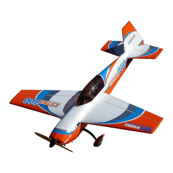
Summary of Contents for AeroWorks 30cc EXTRA 300 ARF-QB
- Page 1 30cc EXTRA 300 ARF-QB (Quick Build) ASSEMBLY MANUAL AEROWORKS 4903 Nome Street, Denver, CO. 80239 - Phone 303-371-4222 - Fax 303-371-4320 E-mail - info@aero-works.net...
-
Page 2: Table Of Contents
Electric Motor Installation ….……………………………………………………………..……. 83 Preflight Preparation ……………………………………………………………………………. 88 Decal installation …………………………………………………………………………………. 91 Center of Gravity CG Buddy…………………………………………………………………….. 92 Center of Gravity (C.G.) / Control Throws …………………………………………………….. 94 Control Throw Deflection Table ……………………………………………………………...… .97 Accessories Available from Aeroworks ………………………………………………………… 99... -
Page 3: Aeroworks Contact Information
Further, Aeroworks reserves the right to change or modify this warranty without notice. In that Aeroworks has no control over the final assembly or materials used for final as- sembly, No liability shall be assumed nor accepted for any damage resulting from the use by the user of the final user-assembled product. -
Page 4: Introduction
INTRODUCTION Your new 30cc EXTRA 300 ARF-QB is a highly aerobatic airplane. It is capable of both precision and 3D maneuvers. The aircraft builds easily, quickly, and precisely due to its state of the art CAD design, LASER cut technology, and high quality included hardware. We hope you enjoy building and flying your 30cc EXTRA 300 ARF-QB. -
Page 5: Kit Contents
KIT CONTENTS (4) #6 bonded washers for the mounting of the canopy 30cc Extra 300 ARF-QB (4) 3mm split lock washers for the mounting of the Materials List canopy (1) 3.5 OD x 800mm Antenna tube installed Basic Aircraft Parts (2) 3.5 OD x 80mm pull-pull exit tube installed... - Page 6 hole for cotter pin with nuts for ailerons and elevators (6) pin point hinges installed (1) Wrench for the left hand and right hand threaded (1) Aileron servo string installed pushrod (4) brass spacers – 2 for ailerons; 2 for elevators; Horizontal Stabilizer with elevator assembly with (8)-4 (8) 4-40 Ball Link –...
- Page 7 #10: (1)Throttle servo mounting tray (2) Air Scoops for Electric Motor (3) Engine Mounting Template (DLE 30; Saito 1.80 4stk/OS 1.60 2stk and Universal) (2) 8x8x300mm Sponge for the receiver and battery (3) 356x12.5mm Velcro (1) Card Stock (8”x11”) for making the template for cutting of cowling (1) Paper Degree Meter for the Rudder - Small (1) 12mm Aluminum Insert...
-
Page 8: Hardware Needed To Complete
8 - Motor mounting bolts ◊ 3’ - Large Gas Fuel Line ◊ 1 - 19x8 Propeller Note: DLE 30 and J’Tec Muffler can be purchased through Aeroworks. Motor Option 4: Electric ◊ 1 - Rimfire 1.60 Outrunner Motor Part # GPMG4795 ◊... - Page 9 ◊ 1 - 2 3/4” Spinner- Carbon Fiber Recommended If flying more aggressive aerobatics please see servo option two below. Note: Spinner available from Aeroworks Note: Servos available through Aeroworks ◊ 5 - Hitec 5645MG Servos for flight surfaces ◊...
- Page 10 HARDEWARE NEEDED TO COMPLETE Receiver Power System : Recommended Extensions: 22 AWG extensions are recommended through out The Aeroworks 20cc-30cc Power package is recom- the 30cc Extra. The following sizes will be used: mended. The package consists of the following items: ◊...
-
Page 11: Tools Needed To Complete
BUILDING ACCESSORIES NEEDED TO COMPLETE Adhesives Tools • 15-30 Minute epoxy • • Blue Loctite Allen wrenches US and Metric. • • Epoxy mixing cups, mixing sticks, brushes Dremel cutting disc and sanding drum tool • • CA kicker (optional) Electric drill and selection of bits •... -
Page 12: Tightening And Re-Shrinking The Covering
TIGHTENING AND RE-SHRINKING THE COVERING 1. Open your kit slowly and take care not to dam- 3. If bubbles persist, use a small pin to punch holes age any parts of the kit. Remove all parts from in the bubble to relieve trapped air and reheat. their plastic protective covers for inspection. -
Page 13: Ultracote™ Colors
Ultracote™ Colors 1. Your model is covered with Ultracote™ covering. In case of repairs, the colors are: Orange/Blue Scheme Orange #877 Sky Blue #875 White #870 Silver #881... -
Page 14: Check Seams And Overlaps For Good Seal
Aeroworks is not responsible for failure of covering seams or overlaps during flight. Note: If covering continues to lift apply a small amount of thin CA underneath the covering. -
Page 15: Checking Hinges For Proper Throw
CHECKING HINGES FOR PROPER THROW If the elevator hinges are tight follow the IMPORTANT same process as described for the wings. If control surfaces will not throw to full deflec- tion it may be necessary using a heat gun to Note: Once these steps have been completed apply heat to the knuckle of each hinge. -
Page 16: Checking Glue Joints
CHECKING GLUE JOINTS 1. Go over all seams and glue joints with thin CA, this will ensure your model lasts for many sea- sons to come. Note: Even if you can visibly see glue on all glue joints it is still recommended that the joints be reglued. -
Page 17: Wing Assembly
2. Attach the 6” extension to the servo lead and 4. Fasten the pull string from the servo hole to the secure with Aeroworks Safety Clip. Ensure the male plug of the servo extension. connectors will not come apart from vibration or light tension. - Page 18 5. Draw the servo extension through the wing and 7. Install servo with servo mounting screws. pull through the wing root rib. Note: Taping servo lead to the inside of the wing panel will help to prevent lead from dropping back inside of wing panel during transportation Pushrod / Control Horn Installation...
- Page 19 2. Assemble the pushrod and control horn assem- 4. Place the control horns over the predrilled bly as shown. The ball link goes between the mounting holes. left and right sides of the control horn sides and is secured with a nylon lock nut. Start with the center hole in the control horn.
- Page 20 6. Securely fasten the control horn to the aileron 8. Use the supplied adjustment wrench to adjust the with six wood screws. pushrod as shown below. Note: CA glues have a fast drying time. Remember to work quickly. 9. Use the opposite end of the adjustment wrench 7.
- Page 21 10. Ensure the servo does not bind at either end point at full deflection. A 1” servo arm is rec- ommended for best results. A 1 1/4” servo arm is required for full deflection of the aileron bevel. 11. Repeat all the above steps for the other wing.
-
Page 22: Stab And Elevator Assembly
5. Draw the servo extension through the fuse and 2. Attach the 24” extension to the servo lead and pull through to the radio compartment. secure with Aeroworks Safety Clip. Ensure the connectors will not come apart from vibration or light tension. - Page 23 2. Assemble the pushrod and control horn assem- 6. Install servo in servo well with the output arm bly as shown. The ball link goes between the toward the tail. Mark and drill location of servo left and right sides of the control horn sides and mounting holes.
- Page 24 4. Place the control horns over the predrilled 7. Use the supplied adjustment wrench to adjust the mounting holes. pushrod as shown below. Note: Control horns have been set at a slight offset to allow for maximum torque at full deflection 5.
- Page 25 9. Finished elevator servo installation shown be- low.
-
Page 26: Rudder And Pull-Pull Cable Assembly
RUDDER AND PULL – PULL CABLE ASSEMBLY 3. Mix epoxy in mixing cup and use a tapered stick Rudder Installation to apply the epoxy inside the pre-drilled holes in the trailing edge of the fin. Apply epoxy to one 1. Gather the rudder, five hinges, rubbing alcohol, side of each hinge and insert the hinge com- petroleum jelly and epoxy materials as shown. -
Page 27: Servo Installation
5. Mix epoxy in mixing cup and use a tapered stick 7. Ensure there is no gap between fin and rudder. to apply the epoxy inside the pre-drilled holes in Allow epoxy to fully cure. Check you have full the leading edge of the rudder. Apply epoxy to rudder deflection before epoxy fully cures. - Page 28 2. Gather the rudder control horn parts as shown 4. Place the control horns over the predrilled below. (2) ball link assemblies, (2) left and (2) mounting holes. right side control horns. Assemble the ball links between the control horns as shown. Secure with nylon lock nut.
- Page 29 6. Mount rudder control horns using six wood 9. Install the rudder servo in the servo cutout with screws. the output shaft to the front. 7. Repeat the above steps for mounting the other Note: Remove balsa stick holding the elevator pull side rudder control horn.
- Page 30 11. Pull the rudder cables from rear of fuse to the 13. Thread cable through brass swage tube. rudder servo tray. Note: Cables run parallel down fuse and do not cross each other. 12. Using an X-ACTO knife clean away any burrs 14.
- Page 31 15. Loop the cable back through the brass swage 17. Cut off excess cable as shown tube and pull tight. 16. Crimp the brass swage tube with a crimping tool 18. A drop of thin CA may be applied to the swage or pliers.
- Page 32 19. Attach ball links to the rudder servo arm and 21. Tape the rudder balance tab to the top leading then attach the servo arm to the rudder servo as edge of the vertical fin in the neutral position as shown.
-
Page 33: Tail Wheel Installation
23. Follow the same steps for the opposite side of 2. Align rudder tiller steering arm with pre drilled the rudder as shown below. Rudder pull pull as- mounting holes at bottom of rudder. sembly is now complete. Tail Wheel Installation 1. - Page 34 4. Mount the tail wheel steering tiller using two 6. Place a drop of thick CA on tail wheel strut wood screws. mounting screws before inserting in the pre- drilled mounting holes on the bottom rear of the fuse. 5. Align the tail wheel with pre drilled mounting 7.
- Page 35 8. Attach the steering spring to the rudder tiller. 10. With spring centered between tiller arms and tail Center the spring between both tail wheel and wheel centered, bend spring wire through tail steering tillers. wheel steering tiller. Note: Tape the rudder counter balance in place to keep the rudder straight.
- Page 36 12. Repeat spring installation for other side.
-
Page 37: Main Landing Gear, And Wheel Pants Assembly
MAIN LANDING GEAR AND WHEEL PANT ASSEMBLY 3. Assemble the landing gear bolts with lock Main Landing Gear Installation washer and flat washer. Use a drop of blue Loc- tite on landing gear bolts before attaching the Gather the landing gear parts as shown below. landing gear. - Page 38 8. Tighten the lock nut against the landing gear 6. Align the flat sides of the axle bolt vertical and strut to secure axle. snug the lock nut against the landing gear strut. Note: Do not tighten securely yet. Align axle bolt with front of gear 9.
- Page 39 10. Install the wheel and outer wheel collar. Use 12. Repeat above steps for other wheel and wheel blue Loctite on the wheel collar set screw before pant. final tightening. 13. Final landing gear installation shown below. 11. Final installation of wheel pant with two mount- ing bolts.
-
Page 40: Stroke Engine Installation
2 STROKE ENGINE INSTALLATION 2. Align cowl to fuse and bolt in place. Mark the Engine Installation location of the air exit from the fuse onto the 1. Gather the items shown below for engine instal- cowling. lation. ◊ Glow engine of your choice This step will help with the proper alignment ◊... - Page 41 4. Tape the engine mounting template to the fire- 6. Use a 8-32 bolt along with a large fender washer wall as shown. to install the blind nuts as shown below. Note: Ensure engine thrust lines on firewall and 7. Tighten the bolt until the blind nut is fully seated template align perfectly in the firewall.
- Page 42 9. Slide the plywood standoffs onto the motor 11. Using mounting bolts and flat washers mount mount mounting bolts as shown below. Align engine mount to firewall. Tighten the bolts bolts with blind nuts installed evenly to prevent crushing of the firewall. 10.
- Page 43 13. Adjust the engines position until the thrust 15. Use a drill bit to drill the engine mounting holes washer is 6 1/2” away from the firewall. into the engine mount. Note: Drill the engine mounting holes as Mounting Distance is: 6 1/2” straight as possible.
-
Page 44: Stroke Throttle Servo Installation
3. Remove the engine and use a drill bit to drill the Throttle servo installation for 2 stroke hole for the throttle pushrod guide tube engine 1. Gather the following items for the throttle servo installation. ◊ 1 - Throttle servo ◊... - Page 45 5. Install the throttle servo in the preassembled la- 7. Install the servo mount to the inside of the en- ser cut mounting tray as shown below. gine box as shown. Use tape or clamps to en- sure the servo mount does not move until the epoxy sets.
- Page 46 9. Attach the nylon clevis to the carburetor as shown. Use a piece of fuel tubing around the clevis to prevent it from coming undone in flight. 10. Install the pitts muffler at this time. 2 stroke en- gine installation is now complete.
-
Page 47: Stroke Engine Installation
4 STROKE ENGINE INSTALLATION 2. Align cowl to fuse and bolt in place. Mark the Engine Installation location of the air exit from the fuse onto the 1. Gather the items shown below for engine instal- cowling. lation. ◊ Glow engine of your choice This step will help with the proper alignment ◊... - Page 48 4. Tape the engine mounting template to the fire- 6. Use a 8-32 bolt along with a large fender washer wall as shown. to install the blind nuts as shown below. Note: Ensure engine thrust lines on firewall and 7. Tighten the bolt until the blind nut is fully seated template align perfectly in the firewall.
- Page 49 9. Slide the plywood standoffs onto the motor 11. Set the engine in between the left and right mount mounting bolts as shown below. Align mounting rails. It will be necessary to clamp the bolts with blind nuts installed motor in place for the next few steps. 10.
- Page 50 13. Mark the position of the engine mounting holes 15. Using (4) 8-32 mounting bolts, lock nuts, and on the engine mount. Mark the center of each washers, mount the motor to the mount as shown engine mounting hole with a center marking tool below.
-
Page 51: Stroke Throttle Servo Installation
3. Remove the engine and use a drill bit to drill the Throttle Servo Installation For 4 holes for the throttle pushrod guide tube Stroke Engine 1. Gather the following items for the throttle servo installation. ◊ 1 - Throttle servo with mounting screws ◊... - Page 52 5. Install the throttle servo in the preassembled la- 7. Install the servo mount to the inside of the en- ser cut mounting tray as shown below. gine box as shown. Use tape or clamps to en- sure the servo mount does not move until the epoxy sets.
- Page 53 9. Use a pair of wire cutters to remove excess 11. Create a Z-Bend in the throttle pushrod and in- guide tube as shown below. stall onto carburetor arm. 4 Stroke throttle instal- lation is now complete. 10. Mark the position where the Z-Bend will be lo- cated on the throttle pushrod as shown.
-
Page 54: Gas Engine Installation
GAS ENGINE INSTALLATION 2. Locate the laser cut engine mounting template Engine Installation for the DLE-30. If other engines are used the Universal template may be modified for any 1. The 30cc Extra 300 will accept a wide range of mounting pattern engine types. - Page 55 4. Align mounting template with firewall and tape 6. Using mounting bolts and flat fender washers in place. mount engine to firewall. Note: Ensure engine thrust lines on firewall and template align perfectly 7. Use blue loctite to secure the engine mounting bolts in place.
-
Page 56: Gas Throttle Servo And Choke Installation
9. Distance from front of firewall to front of Throttle Servo and Choke Installation engine prop hub is 6 1/2”. Gather the following items for the throttle servo installation. Note: Use aluminum stand offs (supplied with ◊ 1 - Throttle servo with mounting screws engine) and washers (not supplied) to achieve ◊... - Page 57 3. Use a drill bit to drill the holes for the throttle 5. Apply 5 minute epoxy to the side of the servo pushrod. mount that will be in contact with the engine box side. 4. Install the throttle servo in the preassembled la- 6.
- Page 58 7. Assemble ball link to threaded end of pushrod. 9. Assemble brass threaded coupler to 4-40 ball link and ball link and brass spacer to the servo Note: Thread ball link half way onto pushrod to arm as shown below. allow for proper adjustment during final installation.
- Page 59 11. Remove pushrod from throttle arm on carburetor 13. Lightly sand end of pushrod for best bond. and cut throttle pushrod to length. 12. Gather the soldering tools as shown below. 14. Solder the threaded brass coupler to the end of the throttle pushrod.
- Page 60 2. We recommend installing the carburetor choke 15. Attach the throttle pushrod with the 4/40 ball pushrod as shown. Use nylon ties to provide links and secure. Power up the receiver and support and holding friction for the choke push- throttle servo and adjust pushrod for proper op- rod.
-
Page 61: Ignition Installation
IGNITION INSTALLATION 1. Gather the ignition module, battery, switch, 3. Use a 1/4” bit to drill the ignition module regulator and installation parts as shown below. mounting holes. 4. Mount the engine ignition module using nylon tie and foam rubber as shown. 2. - Page 62 6. Switch mounting location is at builders discre- 8. Mount ignition regulator as desired. Secure all tion. Mark the location for the ignition switch connectors with tape, safety clip or similar. using the switch mounting plate for a template. Using a modeling knife cut out the switch hole. Note: Ensure switch location does not interfere with the mounting of the wing.
-
Page 63: Glow Fuel Tank Assembly And Installation
◊ 4 - Small nylon ties ◊ 2’ - Large fuel tubing (Supplied) ◊ 1 - Aeroworks fuel “T”(Not Supplied) Vent Carburetor Fill Line 2. Assemble the stopper as shown below. Use Zip 4. Install the supplied fuel line as shown below. - Page 64 7. Install the tank. Run the fuel pick up line to the 5. Thread nylon ties under tank mounting plate and engine. Secure the tank with the two long nylon center in position. ties trim away any excess nylon tie as shown. 8.
- Page 65 11. Use thick CA to secure fuel dot in fuse. 9. Mark location of fuel filler dot. 12. Feed filler line through dot and plug line into 10. Drill hole to accommodate fuel filler dot. filler plug as shown.
- Page 66 13. For four stroke engines route fuel line above the carb inlet to keep the motor from flooding. 14. Secure fuel pick up line to engine carburetor with small nylon tie.
-
Page 67: Gas Fuel Tank Assembly And Installation
◊ 3’ - Large fuel tubing (Not Supplied) ◊ 1 - Aeroworks fuel “T”(Not Supplied) 2. Locate the (2) supplied brass fuel barbs. Solder a 4. Solder a brass fuel barb to the other end of the brass fuel barb to the fuel line pick up tube. This fuel pick up line. - Page 68 5. Final assembly of rubber fuel stopper with fuel 7. Install the fuel tubing and clunk. Secure the fuel pick up tube shown below. tubing with nylon ties to the pick-up tube and clunk. 6. Install air vent tube into rubber stopper and bend 8.
-
Page 69: Fuel Tank Installation
“T”, fuel filter in the fuel line to the carburetor. filler dot, fuel filter and nylon ties. Note: The fuel “T”, and fuel filter are not supplied, but are available through Aeroworks. Filter Carb Fill... - Page 70 4. Use small nylon ties to secure fuel line. 6. Install foam rubber pad for fuel tank to rest on. Foam rubber will help prevent fuel from foam- Note: Gasoline will cause the fuel line to expand ing or getting air bubbles from engine vibration over time.
- Page 71 8. Gather the fuel filler dot and drill bits as shown 10. Drill hole to accommodate fuel filler dot. below. Note: We recommend you start with a smaller size drill bit then increase the bit size to the correct size to fit your filler dot. This will help prevent the fuse side from splitting or cracking.
- Page 72 12. Feed filler line through dot and plug line into 14. Secure fuel pick up line to engine carburetor filler plug as shown. with small nylon tie. 13. Feed vent line tubing through bottom of fuse. Cut off excess fuel line. 15.
-
Page 73: Pitts Muffler Installation
PITTS MUFFLER INSTALLATION FOR GAS ENGINE 1. Use blue loctite to ensure the muffler mounting bolts do not come loose due to vibration. 2. Attach the muffler to the motor at this time. Note: Muffler will be removed during cowl installa- tion. -
Page 74: Radio Installation
RADIO INSTALLATION 1. Gather the radio components as shown below. 3. Install regulator in accordance with manufactur- Battery, Switch, Regulator if used, receiver, ers recommended installations. foam rubber and Velcro one wrap straps. 2. Mount radio switch in accordance with the 4. - Page 75 5. Install receiver using foam padding and Velcro 7. Typical radio installation shown for heavier en- one wrap strap as shown. gine selections. Note: If models CG is tail heavy move batteries forward. If models CG is nose heavy move batteries to the rear.
-
Page 76: Gas Cowl Installation
COWL INSTALLATION FOR GAS MOTORS 1. Gather the materials as shown below. Template 3. Use a T-Pin to mark the location of the bottom material, hobby knife, ruler, tape, marker and cowl mounting bolts onto the template. pencil. 4. Enlarge mounting holes using a hobby knife as 2. - Page 77 5. Use the bottom cowl mounting bolts to keep the 7. Trace around the head of the engine being care- template secure. This will provide a consistent ful to keep the template in the same location. point of reference when marking and cutting the cowl.
- Page 78 9. Extend the cutout marks on the template from 12. Align template with bottom of cowl. Use a felt the cylinder head to the rear air exit mark made tip marker to transfer the template cutout pattern previously. to the cowl and mark cut location. Note: Pay close attention to the marker you 10.
- Page 79 14. Mount cowl to the fuse using (6) 4-40x16mm button style hex head bolts (6)#6 bonded washers...
-
Page 80: Glow Cowl Installation
COWL INSTALLATION GLOW MOTOR 3. Use a T-Pin to mark the location of the bottom 1. Gather the materials as shown below. Template cowl mounting bolts onto the template. material, hobby knife, ruler, tape, marker and pencil. 4. Enlarge mounting holes using a hobby knife as 2. - Page 81 5. Flip the airplane over and trace the muffler 7. Cut out the template using the line marked in the shape onto the template, and leave 1” of space previous step. Use marks made in step 6 to align between the cutout and the muffler. cut out with air exit on the bottom of the fuse.
- Page 82 9. Align template with bottom of cowl. Use a felt 11. Bolt the cowl in place and slide the template tip marker to transfer the template cutout pattern over it. Use a pen to transfer the location of the to the cowl and mark cut location. Using a rotary cut out onto the cowl.
-
Page 83: Electric Motor Installation
Electric Motor, Battery and ESC installation 1. Gather the following items for electric conver- 3. Use a sharp X-Acto knife to remove the cover- sion: ing from the hot air exits. ◊ 1 - Electrfly 1.60 Outrunner motor ◊ 1 - 80 AMP Speed Control ◊... - Page 84 5. Gather the following items for electric conver- 7. Finished air inlet installation shown below. sion: ◊ 4 - 8-32 Mounting bolts ◊ 4 - 8-32 Blind Nuts ◊ 4 - 8-32 Flat Washers ◊ 2 - Plastic Air inlets ◊...
- Page 85 9. Mark location of motor mount holes on the fire- 11. Use a 8-32 bolt along with a large fender washer wall as shown below. to install the blind nuts as shown below. 12. Tighten the bolt until the blind nut is fully seated in the firewall.
- Page 86 14. Following manufactures instructions mount the 16. Mount the ESC to F1 as shown below. Ensure motor to the mount. Use the supplied 8-32 that the speed control will receive plenty of air- mounting bolts to secure the mount to the fire- flow to keep it from overheating.
- Page 87 18. Attach the loop side of the Velcro to the batter- 20. Finished electric installation shown below. ies as shown. 19. Use two One Wrap Velcro Straps to firmly se- cure the batteries to the tray. Attach straps to the small pieces of Velcro at the fuse sides to help hold the straps in place while batteries are being changed.
-
Page 88: Preflight Preparation
1. Gather (2) 6-32 wing mounting bolts, (2) #8 rub- 3. Attach the 6” extension to the servo lead and ber backed washers and (4) hairpins for prepara- secure with Aeroworks Safety Clip. Ensure the tion of mounting the wings. connectors will not come apart from vibration or light tension. - Page 89 5. Gather (4) 4-40 stab mounting bolts and (4) #6 7. Mount the cowl using the cowl mounting bolts small rubber backed washers. and rubber backed washers. The rubber backed washers are to prevent the fiberglass cowl from cracking and to prevent mounting bolts from loosing from normal engine vibration.
- Page 90 9. Slide the rubber backed washers on the hatch mounting bolts and insert bolts through the hatch mounting holes and into the fuse blind nuts. Tighten snugly but do not over tighten and crush the hatch or the fuse sides.
-
Page 91: Decal Installation
DECAL INSTALLATION Decal installation 1. Decals supplied with the kit may vary from the photos below. Decal installation instructions are for reference purposes only. Gather supplied decals, ruler, scissors, hobby knife, plastic squeegee or credit card, Windex or Application fluid like Rapid Tac. Also, a solu- tion of 1 drop of dish detergent to a cup of water sprayed on the model will assist in proper posi- tioning. -
Page 92: Center Of Gravity Cg Buddy
Center Of Gravity– CG Buddy 1. Aeroworks has included the new CG Buddy 4. Slide wing back against the fuse as shown be- with the 30cc Extra 300 . This handy tool will low. allow the builder to balance the airplane without the need for an assistant. - Page 93 8. Lift airplane from center handle as shown, plane should sit level when lifted. Balance the Extra 300 without fuel in the tank with the batteries installed and READY TO FLY. Try to balance the model by moving the batteries and receiver before adding any ballast.
-
Page 94: Center Of Gravity (C.g.) / Control Throws
1. The amount of control throw should be adjusted using mechanical means as much as possible and 2. Balance the 30cc EXTRA 300 ARF-QB without then electronically with the radio. The control fuel in the tank with the batteries installed and throws are shown in degrees and inches of de- ready to fly. - Page 95 3. Use the widest part of the elevator as shown to 5. Slide the throw meter under the rudder boost tab. measure the elevator throw in inches. 4. Gather the Rudder Throw Meter (Supplied) and 6. Center the throw meter on the rudder using the scotch tape.
- Page 96 7. Secure the tabs to the fin using scotch tape. Use the flight control deflection meter (not supplied) to measure the throws in degrees Prop up the tail of the aircraft until the fuselage is parallel to the table top. 10.
-
Page 97: Control Throw Deflection Table
Control Throw Deflection Table Preflight Checks Low Rate Medium Rate Center of Gravity: Check CG is set properly. Aileron 1 3/4” or 22˚ up 2 1/2” or 30˚ up Engine: The engine should run smoothly at all 1 3/4” or 22˚ down 2 1/2” or 30˚ down throttle settings with smooth transition from idle to full throttle without stalling or hesita- Rudder... - Page 98 Aerobatics The 30cc EXTRA 300 ARF-QB is capable of any aerobatic maneuver. After you gain some confi- dence and little experience flying the airplane you can cut loose and perform any maneuver you can think of. Here is a list of some of the more popular aerobatic and 3D maneuvers you can try: •...
-
Page 99: Accessories Available From Aeroworks
Accessories Available From Aeroworks For more information or to order accessories visit our website: WWW.AERO-WORKS.NET Custom Wing/Stab Bags Fuel Line Installation Kit The fuel line installation kit includes everything Designed especially for 30cc-35cc aircraft. The needed to plumb your gasoline powered aircraft. - Page 100 Custom Throw Meter Extra 300 Stick Plane The Extra 300 Stick plane is an accurate replica of Use the Aeroworks Throw Meter to precisely set the 30cc Extra. Use this to practice new maneuvers your control throws on the elevator and ailerons.
- Page 101 30 cc EXTRA 300 ARF-QB NOTES ___________________________________________________________________________ ___________________________________________________________________________ ___________________________________________________________________________ ___________________________________________________________________________ ___________________________________________________________________________ ___________________________________________________________________________ ___________________________________________________________________________ ___________________________________________________________________________ ___________________________________________________________________________ ___________________________________________________________________________ ___________________________________________________________________________ ___________________________________________________________________________ ___________________________________________________________________________ ___________________________________________________________________________ ___________________________________________________________________________ ___________________________________________________________________________ ___________________________________________________________________________ ___________________________________________________________________________ ___________________________________________________________________________ ___________________________________________________________________________ __________________________________________________________________________...
Need help?
Do you have a question about the 30cc EXTRA 300 ARF-QB and is the answer not in the manual?
Questions and answers