
Related Manuals for AeroWorks Sport Cub S2 ARF-QB


Summary of Contents for AeroWorks Sport Cub S2 ARF-QB
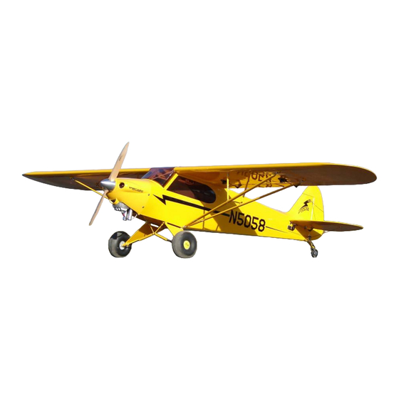
- Page 1 50cc Sport Cub S2 ARF-QB (Quick Build) ASSEMBLY MANUAL AEROWORKS 4903 Nome Street, Denver, CO. 80239 - Phone 303-371-4222 - Fax 303-371-4320 E-mail - info@aero-works.net...
-
Page 2: Table Of Contents
TABLE OF CONTENTS Page Aeroworks Contact Information ………………………………………………………………. 3 Introduction ……………………………………………………………………………………... 4 Kit Contents……………………………………………………………………………………… 5 Items Needed To Complete ……………………………………………………………………... 8 Removing Cockpit Hatch & Instrument Panel ………………………….…………………….. 9 Tightening and Re-shrinking the Covering …………………………………………………… 10 Check Seams and Overlaps for Good Seal ……………………………………………………. 11 Ultracote™... -
Page 3: Aeroworks Contact Information
Tech Support: Techsupport@aero-works.net Thank you for choosing the Aeroworks Sport Cub S2 ARF-QB. We put great effort into making this plane the best model you will ever build and fly. We have provided you with the highest quality kit and performance possible. We wish you great success in the assembly and flying of your new Aeroworks Sport Cub S2 ARF-QB. -
Page 4: Introduction
The Sport Cub S2 ARF-QB is designed for gas engines in the 50cc gas category. DA 50cc engine is shown in the assembly instructions. The aircraft was tested with the DA 50 and has outstanding performance. -
Page 5: Kit Contents
KIT CONTENTS (2) Fuse Rear Side Window, tinted color, preglued 50cc Sport Cub S2 ARF-QB (2) Fuse Front Side Window (functional), Materials List tinted color, pre-installed with the below items: Basic Aircraft Parts (4) Nylon Hinges (2 each side); (8) M2x8mm bolts;... - Page 6 (2) 8-32 blind nuts pre-installed for wing (4) Cooper Spacers mounting (2) 4.25” Rubber Cub S2 wheels with (2) 6-32 blind nuts pre-installed for wing aluminum hub struts mounting (2) Hub caps - painted (5) Large Pin Point Hinges glued for (6) M2x5mm Phillip head bolts for caps Flap mounting...
- Page 7 # 12 (2) 4-40x300mm threaded pushrods (2) 4-40 Solder threaded coupler with (1) 3/4” thick Hardwood Spacer Block for nuts mounting engine DA50/DLE55 (4) 4-40 Ball Links (1) Engine mounting template for DA 50/ (4) 4-40x16mm hex head bolts DLE55 (4) 4-40 lock nuts (1) Universal Engine Mounting Template (4) Brass spacers...
-
Page 8: Items Needed To Complete
ITEMS NEEDED TO COMPLETE Hardware • Allen wrenches US and Metric. • Dremel cutting disc and sanding drum tool • Electric drill and selection of bits • Razor saw • Flat head screwdriver • Hobby heat gun • Hobby iron and covering sock •... -
Page 9: Removing Cockpit Hatch & Instrument Panel
Removing Cockpit Hatch and Instrument Panel 1. Open your kit slowly and take care not to dam- 3. DO NOT use a heat gun near the side windows. age any parts of the kit. Remove all parts from Heat applied directly to these surfaces will cause their plastic protective covers for inspection. -
Page 10: Tightening And Re-Shrinking The Covering
TIGHTENING AND RE-SHRINKING THE COVERING 1. Before doing any assembly or installation of any If bubbles persist, use a small pin to punch decals it is very important to re-shrink or re- holes in the bubble to relieve trapped air and tighten the already applied covering. -
Page 11: Check Seams And Overlaps For Good Seal
It is the responsibility of the purchaser / operator to check the covering seams and overlaps for security and a good seal. Aeroworks is not responsible for failure of covering seams or overlaps during flight. Note: If covering continues to lift apply a small amount of thin CA underneath the covering. -
Page 12: Ultracote™ Colors
Ultracote™ Colors 1. Your model is covered with Ultracote™ covering. In case of repairs, the colors are: Red/White Scheme True Red #866 Black #874 White #870 Yellow/Black Scheme Cub Yellow #884 Black #874... -
Page 13: Wing Assembly
WING ASSEMBLY 3. Attach the 18” extension to the servo lead and Aileron/Flap Servo Installation secure with Aeroworks Safety Clip. Ensure the 1. The ailerons/flaps have been pre-hinged and connectors will not come apart from vibration or glued to the wing panels and are ready for flight. - Page 14 5. Pull aileron extension through root end of wing. 7. Install servo in servo well with the output arm toward the leading edge of the wing. Drill holes for servo mounting screws. 6. Pull flap extension through root end of wing. 8.
- Page 15 9. Finished panel shown with servos installed. 2. Assemble the pushrod and control horn assem- bly as shown. The ball link goes between the left and right sides of the control horn sides and is secured with a nylon lock nut. Start with the center hole in the control horn.
- Page 16 6. Align the left and right sides of the control horns 4. Align the control horns over the factory drilled to the mounting holes and mount using six wood holes. screws as shown. 7. Use tape to hold aileron in the neutral position. 5.
- Page 17 3. Bolt the remaining strut mount in place as Strut assembly and Installation shown. 1. Gather the following items for the strut installa- tion as shown below. ◊ 2 - strut mounts ◊ 2 - 6-32 mounting bolts ◊ 2 - strut eyelets 4.
- Page 18 5. Apply a small drop of medium CA to the strut 7. Finished strut mount and eyelet assembly shown eyelet as shown. Screw the eyelet into the pre- below. Repeat the same steps for the remaining drilled hole in the bottom of the wing. wing before continuing.
- Page 19 9. The foam transportation pad can slip over the 11. Be careful not to over tighten the bolts as this two eyelets and kept in place using the set pins will keep the struts from pivoting into place. and cotter pins. This will prevent the struts from damaging the wing during transport.
- Page 20 13. Cotter pin installation shown below. 15. Finished strut assembly shown. Remove the bot- tom set pins to fully collapse the strut as shown below. 14. The remaining 6-32 bolts will be used to mount the struts to the fuse. It is recommended that these stay in the struts during transport to insure they will not be misplaced.
-
Page 21: Rudder And Pull-Pull Cable Assembly
RUDDER AND PULL – PULL CABLE ASSEMBLY 3. Epoxy the hinges into the fin first and allow ep- Rudder Installation oxy to fully cure. 1. Gather the rudder, four hinges, rubbing alcohol, petroleum jelly and epoxy materials as shown. Use 15-30 minute epoxy to ensure adequate working and cleanup time. -
Page 22: Servo Installation
5. Carefully slide the rudder onto each hinge and 8. Install the rudder servo in the servo cutout with against the trailing edge of the fin. Wipe away the output shaft to the front. excess epoxy with alcohol wetted wipes. Note: Remove balsa stick holding the elevator pull strings at this time. - Page 23 2. Gather the rudder control horn parts as shown 4. Place the control horns over the predrilled below. Two ball link assemblies, two left and mounting holes. two right side control horns. Assemble the ball links between the control horns as shown. Se- cure with nylon lock nut.
- Page 24 6. Mount rudder control horns using six wood 9. Pull the rudder cables from rear of fuse to the screws. rudder servo tray. Note: Cables run parallel down fuse and do not 7. Repeat the above steps for mounting the other cross each other.
- Page 25 11. Using an X-ACTO knife clean away any burrs 14. Loop the cable back through the brass swage from brass swags. This will allow the rudder tube. cable to pass through brass swage easily. 12. Thread cable through brass swage tube. 15.
- Page 26 16. Crimp the brass swage tube with a crimping tool 18. A drop of thin CA may be applied to the swage or pliers. tube to help secure the cable. 17. Cut off excess cable as shown 19. Attach ball links to the rudder servo arm and then attach the servo arm to the rudder servo as shown.
- Page 27 20. Attach servo arm to servo as shown below. 22. Tape the rudder balance tab to the top leading edge of the vertical fin in the neutral position as shown. This ensures the rudder is straight when the cables are attached. 21.
- Page 28 24. Follow the same steps for the opposite side of the rudder as shown below. Rudder pull pull as- sembly is now complete.
-
Page 29: Stab And Elevator Assembly
◊ 2 - 1 1/4” Servo arms ◊ 2 - 36” servo extensions ◊ 2 - Aeroworks safety clips ◊ 8 - Servo mounting screws Nose 4. Install the left elevator servo as shown below. The output shaft will face rearward on the left IMPORTANT elevator assembly. - Page 30 5. Mounting the elevator servos in opposing direc- 7. Install servo with servo mounting screws. tions will allow the servo spline to align per- fectly which will result in equal throw and elimi- nate the need for a Y reverser or complex radio mix.
- Page 31 2. Assemble the pushrod and control horn assem- 4. Place the control horns over the predrilled bly as shown. The ball link goes between the mounting holes. left and right sides of the control horn sides and is secured with a nylon lock nut. Start with the center hole in the control horn.
- Page 32 6. Mount the control horn using six wood screws. 2. Pass the 6-32 x 15mm bolts through the hole at the front of the stab and the 6-32 x 20mm bolts through the hole at the rear of the stab and into the L brackets as shown.
- Page 33 4. Slide the carbon support rod into the stab and 6. Bolt the stab to the fuse as shown below. Be then slide the support rod through the slot in the careful not to over tighten or strip the bolt. fuse as shown.
- Page 34 8. Repeat the previous steps for the remaining stab 2. 1 degree of positive incidence can be achieved assembly. by pushing the stab to the very top of the mount- ing slot. This stab location is recommended for towing purposes. To help raise the tail due to the weight of towing.
-
Page 35: Flying Wire Installation
4. Once the desired position has been located, se- 2. Test fit the top flying wires as shown, the upper curely tighten the mounting bolts. flying wires will be longer than the bottom. Stab Flying Wire Installation 1. Gather the following items shown below. ◊... - Page 36 4. Loosen the lock nut and adjust the flying wire to 6. Pass the 4-40 mounting bolt through the bottom the correct length as shown. flying wire stab mount and install the 4-40 nut as shown. 5. Once wires are the correct length pass the 4-40 7.
- Page 37 8. Use wood screws to secure the bottom flying 10. Stabilizer assembly is now complete. wires to the fuse as shown below. 9. Adjust the flying wire lengths to ensure that the flying wires are not twisting the stabs. The fly- ing wires should be adjusted so they are only able to move about 1/2”...
-
Page 38: Main Landing Gear Installation
MAIN LANDING GEAR ASSEMBLY 1. Gather the following items shown below for the 3. Mount the other rear landing gear/strut mount as main landing gear assembly. shown below. ◊ 2 - Landing gear struts ◊ 2 - Shock absorbers ◊ 1 - Shock mount ◊... - Page 39 5. Slide the landing gear strut in place as shown, 7. Install the remaining landing gear strut following the tapered edge of the strut goes towards the tail the previous mounting instructions. of the airplane. 6. Use 6-32 mounting bolts and 6-32 lock nuts to 8.
- Page 40 9. Slide shock mount onto the bolt followed by 11. Attach shock to shock mount using a 6-32 bolt another brass spacer as shown. Secure the and lock nut as shown. mounting bolt with a 6-32 lock nut. 10. Repeat the steps for the remaining side. Final 12.
- Page 41 13. Final shock installation shown below. 15. Gather the two stock wheels, two wheel spacers, four wheel collars, two hub caps, and six hub cap mounting screws as shown. 14. Repeat the steps for the remaining side. Final 16. Slide one of the wheel spacers onto the axle as installation of shocks shown below.
- Page 42 17. Slide the wheel collar onto the axle as shown. 19. Using the 3 mounting screws, mount the hub cap Tighten the set screw at this time. as shown below. 18. Slide the wheel followed by the remaining wheel 20. Repeat the wheel mounting steps for the follow- collar onto the axle.
-
Page 43: Optional "Tundra" Tire Assembly
◊ 6 - Hub cap mounting screws Note: “Tundra” tires are an optional accessories available through Aeroworks. 4. Using the 3 mounting screws, mount the hub cap as shown below. 2. Slide the spacer followed by the wheel onto the axle. -
Page 44: Tail Wheel Assembly
Tail Wheel Installation 1. Gather the tail wheel parts shown below. 3. Apply a drop of thick CA to the tiller arm mounting screws before inserting in the pre- ◊ 1 - Tail wheel assembly drilled holes. ◊ 1 - Tail wheel leaf spring ◊... - Page 45 5. Place a drop of thick CA on tail wheel strut 7. Tape the rudder boost tab in place to keep the mounting screws before inserting in the pre- rudder aligned while tightening the steering drilled mounting holes on the bottom rear of the springs.
- Page 46 9. Twist spring end tight with pliers. 11. Bottom view of completed tail wheel installa- tion. 10. Repeat spring installation for other side.
-
Page 47: Engine Installation
ENGINE INSTALLATION Engine Installation 3. Locate the laser cut engine mounting template/ mounting plates for either the DA-50 or 1. The 50cc Sport Cub S2 will accept a wide range DLE-55. If other engines are used the Universal of engine types. The DA-50 rear carburetor template may be modified for any mounting pat- engine with Pitts style muffler, was mounted and tern. - Page 48 6. Gather the engine mounting template and stand- 8. Drill through the engine mounting template and off block shown below. into the stand off block as shown. Use a drill press for best results. 7. Use 5 minute epoxy to glue the mounting tem- 9.
- Page 49 10. Install all four mounting bolts as shown. 12. Slide a fender washer, 1/4” standoff, and another fender washers onto the bolts as shown. Note: Fender washers are not included with the kit. 11. Slide the mounting block on the bolts as 13.
-
Page 50: Throttle/Choke Installation
14. Distance from front of firewall to front of 2. Use a 1/4” bit to drill a pushrod exit hole in the engine prop hub is 7 7/8”. firewall in line with the engine carburetor throt- tle arm. Note: Use aluminum spacers (supplied) and washers (not supplied) to achieve correct distance. - Page 51 4. Attach throttle pushrod to the carburetor throttle 6. Test fit throttle servo mounting box in the fuse arm with the 4/40 ball link. as shown. 5. Gather the supplied throttle servo mount as 7. Install throttle servo into servo mounting tray. shown.
- Page 52 8. Apply 5 minute epoxy to the servo mounting 10. Assemble brass threaded coupler to 4-40 ball box as shown. link and ball link and brass spacer to the servo arm as shown below. 9. Place servo mounting box in fuse use tape or 11.
- Page 53 12. Remove pushrod from throttle arm on carburetor 14. Lightly sand end of pushrod for best bond. and cut throttle pushrod to length. 13. Gather the soldering tools as shown below. 15. Solder the threaded brass coupler to the end of the throttle pushrod.
- Page 54 16. Attach the throttle pushrod with the 4/40 ball If a manual choke will be installed gather the links and secure. Power up the receiver and choke pushrod, ball link, wheel collar and throttle servo and adjust pushrod for proper op- nylon ties as shown.
- Page 55 20. Location of manual choke pushrod shown be- low.
-
Page 56: Ignition Installation
IGNITION INSTALLATION 1. Gather the ignition module, battery, switch, 3. Use a 1/4” bit to drill the ignition module regulator and installation parts as shown below. mounting holes. 4. Thread nylon tie through mounting holes. 5. Roll the supplied foam rubber to make a 4 layer pad as shown. - Page 57 6. Secure ignition module with nylon ties as 8. Mount ignition regulator as desired. Secure all connectors with tape, safety clip or similar. necessary. 7. Mount ignition battery behind firewall with ny- 9. Switch holes are precut, inside of fuse as shown lon tie and foam padding.
- Page 58 11. Finished switch and regulator installation shown below.
-
Page 59: Fuel Tank Assembly And Installation
FUEL TANK ASSEMBLY AND INSTALLATION 3. Assemble the fuel pick up line, rubber stopper Fuel Tank Assembly and metal end caps. As shown below. 1. Gather the fuel tank parts as shown below. ◊ 1 - Fuel tank ◊ 1 - Hardware ◊... - Page 60 5. Final assembly of rubber fuel stopper with fuel 7. Install the fuel tubing and clunk. Secure the fuel pick up tube shown below. tubing with nylon ties to the pick-up tube and clunk. 6. Install air vent tube into rubber stopper and bend 8.
-
Page 61: Fuel Tank Installation
“T”, fuel filter in the fuel line to the carburetor. filler dot, fuel filter and nylon ties. Note: The fuel “T”, and fuel filter are not supplied, but are available through Aeroworks. Filter Carb Fill... - Page 62 4. Use small nylon ties to secure fuel line. 7. Install the tank. Run the fuel pick up line to the engine. Secure the tank with the two long nylon Note: Gasoline will cause the fuel line to expand ties trim away any excess nylon tie as shown. over time.
- Page 63 9. Secure fuel pick up line to engine carburetor 11. Mark location of fuel filler dot. with small nylon tie. 10. Gather the fuel filler dot and drill bits as shown 12. Drill hole to accommodate fuel filler dot. below. Note: We recommend you start with a smaller size drill bit then increase the bit size to the correct size to fit your filler dot.
- Page 64 13. Use thick CA to secure fuel dot in fuse. 14. Feed filler line through dot and plug line into filler plug as shown. 15. Feed vent line tubing through bottom of fuse. Cut off excess fuel line. Note: Place a zip tie around the vent line as shown. Be careful not to tighten the zip tie to the point of closing the vent line.
-
Page 65: Pitts Muffler Installation
Pitts Muffler Installation 1. Gather the custom 50cc slim fit muffler avail- able through Aeroworks. This muffler will fit fully enclosed in the cowl. 2. Install pitts muffler using mounting bolts sup- plied with muffler. Note: Use blue loctite on muffler bolts to ensure... -
Page 66: Canister Installation
CANISTER INSTALLATION Canister Installation 2. Use a hobby knife to remove the covering around the hot air exit holes. Gather the canister muffler parts as shown: ◊ 1 - KS 86 Canister (Rear Exit) ◊ 1 - 25mm Drop Double Bend flex header ◊... - Page 67 4. Remove engine from mounts as shown. This will 6. Install the canister mount in the fuse. Allow ep- make canister installation easier. oxy to fully cure before moving on to the next step. 5. Use 30 Minute epoxy to secure the canister Canister mount viewed from front as shown be- mount as shown.
- Page 68 8. Assemble the canister to the header with the Tef- 10. Reinstall motor to mounts. lon coupler and clamps in accordance with manufactures instructions. 11. Secure the header in place using the mounting bolts and gasket provided with your engine. Use blue Loctite to secure the bolts.
- Page 69 13. Canister installation is now complete.
-
Page 70: Cowl Installation
COWL INSTALLATION 1. Gather the materials as shown below. Template 3. Align the template to the bottom of the fuse as material, hobby knife, ruler, tape, marker and shown. Mark the location of the template on the pencil. fuse. Mark Here 2. - Page 71 5. Trace around the head of the engine being care- 8. Install muffler and enlarge template to accom- ful to keep the template in the same location. modate muffler opening as shown below. 6. Use a hobby knife to cut out the engine cylinder 9.
- Page 72 10. Remove the template and use a rotary cutting 2. Mark the location of the header pipe. As shown tool and sanding drum to cut out the openings in below. the cowl. Note: Take care not to cut or scratch the cowl.
- Page 73 5. Use a pen to mark the location of the template 7. Bolt cowling in place and reinstall template as on the fuse. Be careful not to dent the wood shown below. sheeting with the pen. 8. Align template with bottom of cowl. Use a felt tip marker to transfer the template cutout pattern to the cowl and mark cut location.
-
Page 74: Radio Installation
Velcro one wrap straps. 2. Final switch positioning is left to the builder. 4. Install regulator in accordance with manufactur- Aeroworks recommends the switches be in- ers recommended installations. stalled inside the radio bay near the door for easy access as well as improved scale appear- 5. -
Page 75: Radio Installation
6. Run aileron and flap extensions from the re- 8. Reinstall dash panel with the (4) Phillips head ceiver, behind the rear window and out the top screws as shown. of the fuse as shown. This will help maintain the scale appearance of airplane. -
Page 76: Decal Installation
DECAL INSTALLATION 3. Placement of optional decal package shown, in- Decal installation cluded decals will differ. 1. Decals supplied with the kit may vary from the photos below. Decal installation instructions are for reference purposes only. Gather supplied decals, transfer tape, ruler, scis- sors, hobby knife, plastic squeegee or credit card, Windex or Application fluid like Rapid Tac. - Page 77 5. Position fuselage decal as shown below. Mark 7. Use a covering iron to reseal the covering as location where N numbers cross the black strip shown. on the fuse. 6. Remove portion of fuse strip that will be behind 8.
- Page 78 9. Spray back side of decal with application fluid, 11. Using a plastic squeegee or credit card. Spread Windex or soapy water solution. decal smooth and remove all excess application fluid. Let decal set until dry enough to be able to remove transfer tape with out removing decal.
-
Page 79: Preflight Preparation
1. Slide the wing tube in the fuse wing tube sleeve. 3. Secure the aileron and flap connectors with Slide the wings on the wing tube Aeroworks Safety Clip. Ensure the connectors will not come apart from vibration or light ten- sion. - Page 80 5. Gather four 8-32 wing mounting bolts and four #8 rubber backed washers for preparation of mounting the wings. 6. Slide the rubber backed washers on the wing mounting bolts and insert bolts through the fuse side and into the wing root blind nuts. Tighten snugly but do not over tighten and crack the fuse or wing root wood.
-
Page 81: Center Of Gravity- Cg Buddy
5” Back From The Wing Leading Edge Measured From the Root End of the Wing 1. Aeroworks has included the new CG Buddy 4. Slide wing back against the fuse as shown be- with the Sport Cub S2. This handy tool will al- low. - Page 82 8. Lift airplane from center handle as shown, plane should sit level when lifted. Balance the Sport Cub S2 without fuel in the tank with the batteries in- stalled and READY TO FLY. Try to balance the model by moving the batteries and receiver before adding any ballast.
-
Page 83: Control Throws
5. Gather the Rudder Deflection Meter (Supplied) Control Throws and scotch tape. 1. The amount of control throw should be adjusted using mechanical means as much as possible and then electronically with the radio. The control throws are shown in degrees and inches of deflec- tion measured at the widest point of the control surface for both low and high rates. -
Page 84: Control Throw Deflection Table
7. Secure the tabs to the fin using scotch tape. Control Throw Deflection Table Low Rate Medium Rate Aileron 7/8” or 20˚ up 1 1/4” or 30˚ up 7/8” or 20˚ down 1 1/4” or 30˚ down Rudder N/A” or 25˚ left N/A”... -
Page 85: Preflight Checks
Preflight Checks Center of Gravity: Check CG is set properly. Engine: The engine should run smoothly at all throttle settings with smooth transition from idle to full throttle without stalling or hesita- tion. Do not fly an unreliable engine. Read engine instructions including break in and tun- ing completely. - Page 86 50cc Sport Cub S2 ARF-QB NOTES ___________________________________________________________________________ ___________________________________________________________________________ ___________________________________________________________________________ ___________________________________________________________________________ ___________________________________________________________________________ ___________________________________________________________________________ ___________________________________________________________________________ ___________________________________________________________________________ ___________________________________________________________________________ ___________________________________________________________________________ ___________________________________________________________________________ ___________________________________________________________________________ ___________________________________________________________________________ ___________________________________________________________________________ ___________________________________________________________________________ ___________________________________________________________________________ ___________________________________________________________________________ ___________________________________________________________________________ ___________________________________________________________________________ ___________________________________________________________________________ __________________________________________________________________________...
Need help?
Do you have a question about the Sport Cub S2 ARF-QB and is the answer not in the manual?
Questions and answers