Table of Contents
Advertisement
Quick Links
Download this manual
See also:
Quick Manual
Advertisement
Table of Contents

Related Manuals for Extron electronics HDXP Plus Series


Summary of Contents for Extron electronics HDXP Plus Series
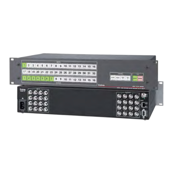
- Page 1 User Guide Matrix Switchers HDXP Plus Series Matrix Switchers 68-1200-01 Rev. B 10 13...
-
Page 2: Safety Instructions
Safety Instructions Safety Instructions • English Инструкция по технике безопасности • Русский WARNING: This symbol, , when used on the product, is intended to ПРЕДУПРЕЖДЕНИЕ: Данный символ, , если указан alert the user of the presence of uninsulated dangerous voltage within the на... - Page 3 “Extron Safety and Regulatory Compliance ” Guide on the Extron website. Copyright © 2013 Extron Electronics. All rights reserved. Trademarks All trademarks mentioned in this guide are the properties of their respective owners. ® The following registered trademarks , registered service marks...
- Page 4 Conventions Used in this Guide Notifications The following notifications are used in this guide: WARNING: A warning indicates a situation that has the potential to result in death or severe injury. Attention indicates a situation that may damage or destroy the product or ATTENTION: associated equipment.
-
Page 5: Table Of Contents
........... 1 Muting and Unmuting Outputs ...... 33 About this Guide ..........1 Locking the Front Panel (Executive Mode)..35 About the HDXP Plus Series Matrix Switchers ..1 Setting the Button Background Features ............. 2 Illumination ..........35 Application Diagrams .......... 5 Selecting the RS-232 or RS-422 Protocol and Baud Rate .......... - Page 6 Uploading Files ........... 107 Adding a Directory ........108 Other File Management Activities ....108 Set and View Ties Page ........109 Creating a Tie ..........109 Output Settings Page ......... 110 Global Presets Page ........111 HDXP Plus Series Switchers • Contents...
-
Page 7: Introduction
Introduction This section gives an overview of the Extron HDXP Plus Series Matrix Switchers, describes significant features of the series, and provides application diagrams. • About this Guide • About the HDXP Plus Series Matrix Switchers Features • • Application Diagrams... -
Page 8: Features
Video Genlock (HDXP 3232 only) — Allows for vertical interval switching, and enables smooth, seamless transitions when switching between synchronous video sources. Separate bi-level (SDI) and tri-level (HD-SDI) references are provided on two additional BNC connectors. HDXP Plus Series Switchers • Introduction... - Page 9 IP Link Global Configurator), the Windows-based control software, and the SIS command set. In addition, the HDXP 3232 has a 2.5 mm TRS configuration port on the front panel, which provides an RS-232 connection only. HDXP Plus Series Switchers • Introduction...
- Page 10 Firmware upgrades are available for download on the Extron website, www.extron.com and they can be installed using the Windows-based control program, SIS commands, or the web pages. HDXP Plus Series Switchers • Introduction...
-
Page 11: Application Diagrams
Extron HDXP Plus Series Multi-Rate Digital Matrix Switcher High Definition Digital Media Servers TCP/IP Remote User and Administration Control Digital Video Tape Recorders Plasma/LCD Displays Projectors (SDI/HD-SDI) Figure 1. Application Diagrams for HDXP Plus HDXP Plus Series Switchers • Introduction... -
Page 12: Installation
Most of the HDXP connectors are on the rear panel. Figures 2, 3, and show the rear panels of the HDXP 1616, 3216, and 3232 switchers. INPUTS OUTPUTS RESET Figure 2. HDXP 1616 Rear Panel INPUTS OUTPUTS RESET Figure 3. HDXP 3216 Rear Panel HDXP Plus Series Switchers • Installation... -
Page 13: Connections
Video outputs — Connect serial digital video output devices to these female BNC connectors. Preview output — Connect a digital display device to this female BNC connector to enable you to preview a selected input when the switcher is in preview mode. HDXP Plus Series Switchers • Installation... -
Page 14: External Sync Connections (Hdxp 3232 Only)
-10dBV COLORBAR BLACKBURST Connect to HDXP Plus 3232. GEN-LOCK T connector Terminate cable or connect to another device. Extron PREVIEW HDXP Plus 3232 Matrix Switcher Figure 5. Simple HDXP 3232 External Sync Connection Example HDXP Plus Series Switchers • Installation... -
Page 15: Reset Button
Hard reset — Hold the Reset button while powering up the switcher to restore • the switcher to the default factory settings and factory installed firmware version. NOTE: This type of reset does not clear the current configuration. HDXP Plus Series Switchers • Installation... -
Page 16: Ethernet Connection
"straight-through" cable because reversed) is a "crossover" cable. no pin or pair assignments are swapped. Both ends of the cable can be T568B (as shown) or T568A (not shown). Figure 7. RJ-45 Connector and Pinout Tables HDXP Plus Series Switchers • Installation... -
Page 17: Rs-232 And Rs-422 Remote Connections
RS-232 port is located on the front panel. A host device can be connected to this port for serial RS-232 control only. Protocol for the port is: 9600 baud • 8 data bits • 1 stop bit • No parity • No flow control • HDXP Plus Series Switchers • Installation... -
Page 18: Power
HDXP. Power AC power connector — Plug a standard IEC power cord into this connector to connect the switcher to a 100 VAC to 240 VAC, 50 or 60 Hz power source. HDXP Plus Series Switchers • Installation... -
Page 19: Operation
Room memory preset — A configuration consisting of outputs in a single room that has been stored. When a room preset is retrieved from memory, it becomes the current configuration for the outputs assigned to that room only (none of the other outputs are affected). HDXP Plus Series Switchers • Operation... -
Page 20: Input And Output Buttons
Identify the selected outputs. ❏ Output 1 only: With the Input 1 button, place the switcher in I/O grouping • mode (see Grouping). Muting and Unmuting Outputs Mute or unmute an output (see on page 33). • HDXP Plus Series Switchers • Operation... -
Page 21: Configuration Port (Hdxp 3232 Only)
• In I/O grouping mode, indicates that group 2 is selected (see Grouping). • Selects the RS-232 or RS-422 protocol and baud rate (see Selecting the • RS-232 or RS-422 Protocol and Baud Rate). HDXP Plus Series Switchers • Operation... -
Page 22: I/O Buttons
Flashes to indicate that the Remote RS232/RS422 port is set to the RS-232 • protocol when the switcher is in Serial Port Configuration mode (see Selecting the RS-232 or RS-422 Protocol and Baud Rate). HDXP Plus Series Switchers • Operation... -
Page 23: Operations
Press the Matrix button in the I/O section. The Matrix button lights green (the Preview button remains unlit). HDXP Plus Series Switchers • Operation... - Page 24 If necessary, place the HDXP in matrix switching mode by pressing and releasing the Matrix button. The button lights steadily green. I / O MATRIX PREVIEW Press the Matrix button to enter matrix mode. The button lights green when selected. Figure 13. Selecting Matrix Mode HDXP Plus Series Switchers • Operation...
- Page 25 Confirming the Tie The configuration now is: Input 5 tied to output 3, output 4, and output 8 Input 5 Tied to Outputs 3, 4, and 8 Input Output Figure 17. Example 1, Final Configuration HDXP Plus Series Switchers • Operation...
- Page 26 CONTROL VIEW ENTER PRESET OUTPUT The Enter button blinks green to indicate the need to = Blinking button confirm the change. Figure 21. Selecting an Additional Output HDXP Plus Series Switchers • Operation...
-
Page 27: Breaking Ties
Press one of the lit output buttons. The button you pressed, and the Enter button, start to blink. Press the Enter button. The input, output, and Enter buttons become unlit, and the tie is broken. HDXP Plus Series Switchers • Operation... - Page 28 The button blinks green to indicate the pending change: output 4 will be untied. VIEW ENTER PRESET The Enter button blinks green to indicate the need to OUTPUT confirm the change. = Blinking button Figure 27. Deselecting the Output HDXP Plus Series Switchers • Operation...
-
Page 29: Previewing An Input
Press the Preview button to enter preview mode. The button lights red when selected. Figure 30. Selecting Preview Mode NOTE: If an input has already been selected in preview mode, its button also lights red when you press Preview. HDXP Plus Series Switchers • Operation... -
Page 30: Viewing The Configuration
> Press the Esc to clear all selections. CONTROL VIEW ENTER PRESET The button blinks once. Figure 32. Clearing All Selections HDXP Plus Series Switchers • Operation... - Page 31 Press the View button to exit view-only mode. All input and output buttons become unlit or return to VIEW background illumination. The View button becomes unlit or returns to background illumination. Figure 35. Exiting View-only Mode HDXP Plus Series Switchers • Operation...
-
Page 32: I/O Grouping
(MPEG-2/JPEG 2000) #1 17 18 19 Monitor 21 22 23 Output Output Group 1 Group 2 SDI/HD-SDI SDI/HD-SDI Monitor Camera #4 SDI/HD-SDI VTR SDI/HD-SDI (MPEG-2/JPEG 2000) #3 Monitor Figure 36. I/O Grouping of Incompatible Video Formats HDXP Plus Series Switchers • Operation... - Page 33 Output 1 button. Press and hold the 17 18 17 18 Input 1 button and the Output 1 button. 3 Seconds Ungrouped input and output buttons light. Outputs Figure 38. Selecting I/O Group Mode HDXP Plus Series Switchers • Operation...
- Page 34 MATRIX PREVIEW Press the Matrix and Preview button simultaneously to exit I/O grouping mode. Figure 41. Exiting I/O Grouping Mode Alternatively, you can allow the mode to time out by waiting approximately 30 seconds. HDXP Plus Series Switchers • Operation...
-
Page 35: Saving And Recalling Presets
17 18 19 20 21 22 23 24 25 26 27 28 29 30 31 32 Preset Preset Preset Preset Preset Preset Preset Preset Preset Preset Preset Preset Preset Preset Preset Preset Figure 42. Preset Locations on the HDXP 3232, 3216, and 1616 HDXP Plus Series Switchers • Operation... -
Page 36: Saving A Preset
The Enter button blinks to indicate the need to save the preset. The Preset button continues to 17 18 19 20 21 22 23 24 blink. = Blinking button Figure 45. Selecting the Preset Number HDXP Plus Series Switchers • Operation... -
Page 37: Recalling A Preset
In the example in figure 48, the Input 2 button lights red, because a preset has been assigned to it. Input button 17 does not light, because no preset has been assigned to it. HDXP Plus Series Switchers • Operation... - Page 38 Inputs 17 18 17 18 Figure 50. Pressing Enter to Recall the Preset < Press and release the View button to return the HDXP to normal switcher operation. HDXP Plus Series Switchers • Operation...
-
Page 39: Muting And Unmuting Outputs
The button blinks green to indicate that the outputs are muted. 2 seconds Press and hold the Output 4 button. The button blinks green to indicate that the outputs are muted. = Blinking button Figure 53. Muting the Outputs HDXP Plus Series Switchers • Operation... - Page 40 = Blinking button Figure 55. Unmuting the Outputs < Press the View button to exit view-only mode, or wait for the front panel to time out after approximately 30 seconds. HDXP Plus Series Switchers • Operation...
-
Page 41: Locking The Front Panel (Executive Mode)
Press and hold the Input 1 and Input 2 buttons simultaneously to toggle background illumination mode on or off. 17 18 2 seconds Release the Input 1 and Input 2 buttons. 17 18 Figure 57. Toggling Background Illumination On or Off HDXP Plus Series Switchers • Operation... -
Page 42: Selecting The Rs-232 Or Rs-422 Protocol And Baud Rate
In this example, the port is set to RS-422 at 38400 baud. = Blinking button I / O C O N T R O L VIEW ENTER PRESET MATRIX PREVIEW Figure 59. Selecting RS-232 or RS-422 and the Baud Rate HDXP Plus Series Switchers • Operation... -
Page 43: Resetting
Continue to hold the Matrix and Preview buttons until all input and output buttons become unlit and the Matrix button lights green. Release the Matrix and Preview buttons. Figure 61. Resetting the System from the Front Panel HDXP Plus Series Switchers • Operation... - Page 44 Mode 5 reset clears most adjustments. To save these settings, use the Matrix Switchers Control Program and select from the menu before you Save MATRIX settings as... File perform this reset (see the Matrix Switcher Control Program help file for more information). HDXP Plus Series Switchers • Operation...
- Page 45 Figure 62. Whole Switcher and Absolute Resets Release the Reset button, then immediately press and release the Reset button again. No reset is performed if the second momentary press does not occur within 1 second. HDXP Plus Series Switchers • Operation...
-
Page 46: Troubleshooting
Ensure an active input is selected for output on the switcher. Ensure that the proper signal format is supplied. Check the cabling and make corrections as necessary. Terminate unused inputs and outputs with 75-ohm BNC connectors. Call the Extron S3 Support Hotline if necessary. HDXP Plus Series Switchers • Operation... -
Page 47: Configuration Worksheets
Output devices include various SDI/HD-SDI monitors. The VTG 400 video test generator connected to input 12 enables a video test pattern to be sent to one, several, or all output devices for problem isolation or adjustment purposes. HDXP Plus Series Switchers • Operation... -
Page 48: Worksheet Example 2: Daily Configuration
Displayed in the Demo Room (output 6) • • The presenter has a presentation stored in the VTR (input 4) that is: Displayed in the main hall (output 2) • Displayed locally on the #2 podium (output 3). • HDXP Plus Series Switchers • Operation... -
Page 49: Worksheet Example 3: Test Configuration
Room monitor Room monitor Output destinations System test Preset # Title: Video ties: Fill in the preset number and use colors, dashes, etc., to make connecting lines. Figure 66. Worksheet Example 3: Test Configuration HDXP Plus Series Switchers • Operation... - Page 50 HDXP Plus Series Switchers • Operation...
-
Page 51: Remote Configuration And Control
The optional 2.5 mm cable can be ordered separately and used to connect the HDXP 3232 Plus to the host serial port. For connection information for this cable, see RS-232 Config connector (front panel) on page 11. HDXP Plus Series Switchers • Remote Configuration and Control... -
Page 52: Ethernet Port
• If the switcher is password-protected, a prompt appears below the Password copyright message. If the switcher is password-protected, enter the appropriate administrator or user password. HDXP Plus Series Switchers • Remote Configuration and Control... -
Page 53: Number Of Connections
The switcher-initiated messages are listed below (underlined). With an RS-232 or RS-422 connection: (c) Copyright 20nn, Extron Electronics HDXP Plus Series, Vn.nn, 60-nnn-01 With an Internet connection: (c) Copyright 20nn, Extron Electronics HDXP Plus Series, Vn.nn... -
Page 54: Switcher Error Responses
— Bad file name or file not found NOTE: User privileges extend to all view and read commands except reading the administrator password. Users can also create ties, creating and recall presets, and mute outputs. HDXP Plus Series Switchers • Remote Configuration and Control... -
Page 55: Using The Command And Response Table For Sis Commands
01 = Bypass 04 = 270 07 = 1485 02 = 143 (component NTSC) 05 = 360 08 = 2970 = Total inputs in the matrix X& = Total outputs in the matrix HDXP Plus Series Switchers • Remote Configuration and Control... - Page 56 = Matrix name (up to 240 characters) The following characters are invalid in the name: NOTE: ~ , @ [ ] { } ' < > " ; \ | and ? HDXP Plus Series Switchers • Remote Configuration and Control...
- Page 57 HDXP 1616: 01 – 16 = Inputs 1 through 16 Power supply: 98 = Notify status for reading (16-digit number). For each digit, 0 = Do not notify 1 = Notify = DHCP status 0 = Off 1 = On HDXP Plus Series Switchers • Remote Configuration and Control...
- Page 58 B = byte (8 bits) S = short (16 bits) L = long (32 bits) This parameter is case sensitive. NOTE: = Event data to write = Number of bytes to read HDXP Plus Series Switchers • Remote Configuration and Control...
- Page 59 0 = neither verbose mode nor tagged responses enabled (default for IP connection) 1 = verbose mode enabled; no tagged responses (default for serial connection) 2 = tagged responses enabled; verbose mode not enabled 3 = both verbose mode and tagged responses enabled HDXP Plus Series Switchers • Remote Configuration and Control...
-
Page 60: Command And Response Table For Sis Commands
0 – maximum number of inputs for your model (0 = untied) = Output number 1 – maximum number of outputs for your model = Mute status for individual output 0 = unmuted, 1 = muted HDXP Plus Series Switchers • Remote Configuration and Control... - Page 61 10 presets assigned. = Global preset number 00 – 32. 00 = current configuration = Video mute status For each output: 0 = no mutes, 1 = video mute HDXP Plus Series Switchers • Remote Configuration and Control...
- Page 62 ) assigned. = Global preset number 00 – 32. 00 = current configuration = Room preset number 1 – 10. Each room ( ) can have up to 10 presets assigned. HDXP Plus Series Switchers • Remote Configuration and Control...
- Page 63 = Room preset number 1 – 10. Each room ( ) can have up to 10 presets assigned. = Signal status, DVSP 1 = signal present at input, 0 = no signal at input HDXP Plus Series Switchers • Remote Configuration and Control...
- Page 64 03 = 177 (component PAL), 04 = 270, 05 = 360, 06 = 540, 07 = 1485, 08 = 2970 = Group number for I/O grouping 0 – 4. 0 = not grouped. HDXP Plus Series Switchers • Remote Configuration and Control...
- Page 65 = Name (for room, room presets, 12 characters maximum for preset names and global presets) 11 characters maximum for room names Valid characters are a–z, A–Z, 0–9, " _ : and {space}. HDXP Plus Series Switchers • Remote Configuration and Control...
- Page 66 1 = lock mode enabled (front panel is locked) = Global preset number 00 – 32. 00 = current configuration = Room preset number 1 – 10. Each room ( ) can have up to 10 presets assigned. HDXP Plus Series Switchers • Remote Configuration and Control...
- Page 67 NOTE: There are up to three separate sets of Extron firmware on which the HDXP can report: the HDXP Plus Series control firmware, which is the overall control firmware; the Ethernet protocol firmware, which handles the Ethernet interface;...
- Page 68 = Daylight saving time (DST) status 0 = off, 1 = off. Daylight saving time (DST) is a 1-hour offset that is observed in the USA and parts of Europe and Brazil. HDXP Plus Series Switchers • Remote Configuration and Control...
- Page 69 0 = RS-232, 1 = RS-422 = Subnet mask Format nnn.nnn.nnn.nnn. Leading zeros in each field are optional. = Gateway IP address Format nnn.nnn.nnn.nnn. Leading zeros in each field are optional. HDXP Plus Series Switchers • Remote Configuration and Control...
- Page 70 Value precedes parameter; for example, 3-byte length = 3L. = Priority status for receive timeouts 0 = Use Send data string command parameters. 1 = Use configure receive timeout command parameters. Default is 0. HDXP Plus Series Switchers • Remote Configuration and Control...
- Page 71 3 = 1 and 2. = Notification selections HDXP 3216 and 3232: 01 – 32 = inputs 1 through 32 HDXP 1616: 01 – 16 = inputs 1 through 16 Power supply: 98 HDXP Plus Series Switchers • Remote Configuration and Control...
- Page 72 (default for IP connection) 1 = verbose mode enabled, tagged responses disabled (default for serial connection) 2 = tagged responses enabled, verbose mode not enabled 3 = both verbose mode and tagged responses enabled HDXP Plus Series Switchers • Remote Configuration and Control...
-
Page 73: Matrix Software
Open the Extron web page and select the tab. Download On the Download Center screen, click the link in the left panel or the Software figure 68 icon in the main panel (see on the next page). Software HDXP Plus Series Switchers • Matrix Software... - Page 74 When you are ready to install the software, double-click on the icon, click Run on the download screen pcss_vnxnxn.exe that opens, and restart this procedure at step 7. HDXP Plus Series Switchers • Matrix Software...
-
Page 75: Software Operation Via Ethernet
(spaces can be used in The following characters are invalid or not recommended: space names) (semicolon) (colon) | + ~ , @ = [ ] { } < > ' " ; HDXP Plus Series Switchers • Matrix Software... -
Page 76: Using The Software
Baud pop-up list (after you click it, the button changes to Baud Double-click on the desired baud rate (available selections are 9600 19200 , and ; the default is 38400 115200 9600 HDXP Plus Series Switchers • Matrix Software... - Page 77 If you logged on with the user password, the Matrix program connects you to • the HDXP switcher with only user capabilities. If an incorrect password is entered, the program beeps and returns to the • password entry display. HDXP Plus Series Switchers • Matrix Software...
- Page 78 The window for the HDXP 3216 has 32 input boxes and 16 output boxes, while the HDXP 1616 window has 16 input boxes and 16 output boxes. Figure 73. Extron Matrix Switcher Control Program Window (No Ties) Figure 74. Sample Matrix Window with Ties and Rooms HDXP Plus Series Switchers • Matrix Software...
-
Page 79: Setting Up The Matrix Window
To remove the icon from a box and leave the box empty, drag an empty square to the box. Alternatively, you can display the input and output numbers in the boxes instead of icons. To do this, select from the drop-down Numbers in I/O Boxes Preferences menu. HDXP Plus Series Switchers • Matrix Software... -
Page 80: Managing Ties
(if captions were specified), details on the connections to that device, and the frequency of the video signal being sent to or from it. Figure 77. Matrix Window Section with Pop-up Information on Input 4 HDXP Plus Series Switchers • Matrix Software... -
Page 81: Ip Setup
Setting an IP Address on page 113 for basic information about IP addresses. HDXP Plus Series Switchers • Matrix Software... - Page 82 Edit the name as desired. Press the <Tab> key on the keyboard or click in another field to exit the Extron field. Name/Descriptor Click the button to make the name change take effect. Take HDXP Plus Series Switchers • Matrix Software...
-
Page 83: Hardware Address Field
NOTE: Selecting or deselecting this check box while connected via Ethernet can immediately disconnect your computer from the HDXP. It is recommended that you connect via RS-232 or RS-422 to edit this field. HDXP Plus Series Switchers • Matrix Software... -
Page 84: Sync Time To Pc Button
When daylight savings time is turned off, the switcher does not adjust its time reference. Select the check box to enable daylight savings time. Use Daylight Savings HDXP Plus Series Switchers • Matrix Software... - Page 85 Make any desired changes to the case-sensitive user password. Press the <Tab> key on the keyboard or click in another field to exit the User field. Password Click the button to make the password change take effect. Take HDXP Plus Series Switchers • Matrix Software...
- Page 86 Edit these fields and controls as follows: Click in the desired field. The graphic cursor becomes a text E-mail Addressee cursor. Edit the e-mail address as desired. Standard e-mail address conventions (such as nnnnn@xxx.com) apply. HDXP Plus Series Switchers • Matrix Software...
-
Page 87: Updating The Firmware
On the Open File - Security Warning window, click Save On the Save As window, browse to the folder where you want to save the firmware file, and click . The firmware installation file is placed on your hard Save drive. HDXP Plus Series Switchers • Matrix Software... - Page 88 HDXP to reset, which will terminate the connection with your computer and close the control software. Click If you want to continue using the Matrix Switcher Control Program, you must restart it. HDXP Plus Series Switchers • Matrix Software...
-
Page 89: Uploading Html Files
Internet browser. Click the button. The file uploading process may take a few minutes. Open Click the button to confirm the upload. Update Click the button to exit the HTML Files List window. Close HDXP Plus Series Switchers • Matrix Software... -
Page 90: Windows Buttons, Menus, And Trash Can
— Selects the target printer that will be used to print tie maps. Select Printer — Prints the tie set that is displayed on the screen. • Print Tie Map • — Closes the Matrix Switcher Control Program. Exit HDXP Plus Series Switchers • Matrix Software... - Page 91 — Displays a list of HTML files installed on the switcher HTML File Manager and allows you to upload custom files from a connected PC to the switcher (see Uploading HTML Files on page 83). HDXP Plus Series Switchers • Matrix Software...
- Page 92 — Displays the ASCII commands that are used by the Show RS-232 strings current configuration. You can refer to these for SIS programming (see the Remote Configuration and Control section beginning on page 45 for information on entering SIS commands). HDXP Plus Series Switchers • Matrix Software...
-
Page 93: Preferences Menu
Take button. When you select this option, the Take buttons are removed from the Matrix window. Cancel • — Delays implementation of Hold/Verify Changes configuration changes until the button is pressed. Take HDXP Plus Series Switchers • Matrix Software... - Page 94 ( ) in the crosspoint box. Ties that Take will be broken when you click the button are indicated by a minus sign ( Take – Figure 87. Ties Shown as Crosspoints HDXP Plus Series Switchers • Matrix Software...
-
Page 95: Using Emulation Mode
To use emulation mode, do the following: Double-click the icon in the Extron MATRIX Switchers + Control Program Electronics group or folder. On the Comm Port Selection window, select , and click Emulate HDXP Plus Series Switchers • Matrix Software... - Page 96 On the Save Emulated Matrix Settings window, enter a file name under which you want to save any changes to the file, and click Save Figure 89. Saving a New Emulation File HDXP Plus Series Switchers • Matrix Software...
-
Page 97: Using The Matrix Switcher Help System
(shown at right). MATRIX Switcher Help Within the Matrix Switcher Control Program, select from the menu on • Contents Help the Matrix window. • From within the Matrix Switcher Control Program, press the <F1> key. HDXP Plus Series Switchers • Matrix Software... -
Page 98: Creating Button Labels
C:\Program Files Program for Windows 7, 32-bit] . The Files (x86) \Extron\ButtonLabelGenerator Button icon is placed in the Extron Electronics group or folder. Label Generator HDXP Plus Series Switchers • Matrix Software... - Page 99 To run the label creation program, double-click on the icon Button Label Generator (shown at right) in the Extron Electronics group or folder. The Button Label Generator window opens. Figure 92. Button Label Generator Window From the menu, select for the...
-
Page 100: Replacing Button Labels
Repeat steps 1 through 6 as needed to relabel other buttons. Plunger Base Diffuser Clear Lens Button Label Pry the two pieces apart. Notch Separating the two- piece button here at the corner. Figure 93. Replacing a Button Label HDXP Plus Series Switchers • Matrix Software... -
Page 101: Blank Button Labels
Blank Button Labels HDXP Plus Series Switchers • Matrix Software... -
Page 102: Html Configuration And Control
The following characters are invalid or not recommended in file names: and {space}. + ~ , @ = ` [ ] { } < > ' " ; : | \ HDXP Plus Series Switchers • HTML Configuration and Control... -
Page 103: Special Characters
The following characters are invalid or not recommended: (semicolon) (colon) | + ~ , @ = ` [ ] { } < > ' " ; space HDXP Plus Series Switchers • HTML Configuration and Control... -
Page 104: System Status Page
You can view a snapshot-in-time of the input frequencies of connected inputs on the Digital Sync Validation Processing (DSVP) page. Click the link on the left panel of the DSVP System Status page to display the DSVP page. Figure 96. DSVP Page HDXP Plus Series Switchers • HTML Configuration and Control... -
Page 105: System Settings Page
45) or using the Extron Matrix Switcher Control Program (see the Matrix Software section beginning on page 67) is password-protected. Connection via the RS232/RS422 port is not password-protected. • HDXP Plus Series Switchers • HTML Configuration and Control... -
Page 106: Ip Settings Fields
For more information, see “Subnetting — A Primer” under “Ethernet Connection” in the “Reference Information” section. MAC Address field The Media Access Control (MAC) Address is hard coded in the switcher and cannot be changed. HDXP Plus Series Switchers • HTML Configuration and Control... -
Page 107: Date/Time Settings Fields
Europe and Brazil. When daylight savings time is turned off, the switcher does not adjust its time reference. Click the button at the bottom of the Date/Time Settings section to implement Submit your selections. HDXP Plus Series Switchers • HTML Configuration and Control... -
Page 108: Passwords Page
To clear an existing password so that no password is required, delete the bullets in the fields and enter a space in each field, then click the Password Re-enter Password button at the bottom of the page. Submit HDXP Plus Series Switchers • HTML Configuration and Control... -
Page 109: Email Settings Page
+ ~ , @ = ` [ ] { } < > ' " ; : | \ and {space}. The character is acceptable only as the lead-in to the domain name (such as @folklore.net HDXP Plus Series Switchers • HTML Configuration and Control... -
Page 110: Email Address Fields
Suspend they are unavailable, such as traveling or vacation. Deleting an e-mail addressee and clicking the button removes the recipient from e-mail notification completely. Save HDXP Plus Series Switchers • HTML Configuration and Control... -
Page 111: Firmware Upgrade Page
Access the HDXP web pages. Select the tab. Configuration On the Configuration page, click the link on the left sidebar menu. Firmware Upgrade Click the button. An Open window is displayed. Choose File HDXP Plus Series Switchers • HTML Configuration and Control... - Page 112 When the uploading process is complete, the button changes back to . The Upload uploading may take a few minutes. When the firmware upload is complete, the new version number is displayed on the Firmware Upgrade and System Status screens. HDXP Plus Series Switchers • HTML Configuration and Control...
-
Page 113: Using The File Management Page
File Management screen. Files are listed separately under headings of their extensions. NOTE: If you want one of the pages that you create and upload to be the default startup page, name that file “index.html.” HDXP Plus Series Switchers • HTML Configuration and Control... -
Page 114: Adding A Directory
HDXP. This menu lets you choose to display only files with the extension you select. Select to display all uploaded files. HDXP Plus Series Switchers • HTML Configuration and Control... -
Page 115: Set And View Ties Page
To tie an input to all outputs, click the input number, located at the left of the matrix. Click the button to make the configuration changes or button to Take Cancel abandon the changes. HDXP Plus Series Switchers • HTML Configuration and Control... -
Page 116: Output Settings Page
To disable the reclocker for the selected output, select • Bypass To mute, unmute, or change the reclocker rate of all the outputs, select or clear the check box. HDXP Plus Series Switchers • HTML Configuration and Control... -
Page 117: Global Presets Page
If you do not rename an existing preset when it is overwritten, the HDXP retains • the same name. Recalling a preset To recall a global preset to be the current configuration, click the button for the desired preset on the Global Presets page. HDXP Plus Series Switchers • HTML Configuration and Control... -
Page 118: Reference Information
Figure 108 shows a diagram of an HDXP 1616 or 3216 being mounted to a standard 19-inch rack. Figure 108. Rack Mounting the HDXP HDXP Plus Series Switchers • HTML Configuration and Control HDXP Plus Series Switchers • Reference Information... -
Page 119: Setting An Ip Address
HDXP Plus switcher 208.132.180.42 NOTE: The host identifiers ( in the above example) do not need to be sequential or in any particular order. However, it is recommended that you group the numbers for simplicity. HDXP Plus Series Switchers • Reference Information... -
Page 120: Subnet Mask
IP address from an alias and to determine the web address. Ping the switcher as follows: From the Windows menu, select . The Run window opens. Start Run... In the text field, enter Open Click . A command window opens. HDXP Plus Series Switchers • Reference Information... -
Page 121: Connecting As A Telnet Client
. The computer returns a display similar to figure 110. telnet Microsoft (R) windows 2000 (TM) Version 5.0 (Build 2195) Welcome to Microsoft Telnet Client Telnet Client Build 5.00.99203.1 Escape Character is 'CTRL+]' Microsoft Telnet> Figure 110. Telnet Screen HDXP Plus Series Switchers • Reference Information... - Page 122 Telnet prompt. If your unset local_echo computer is connected to the HDXP switcher, and you need to access the Telnet prompt to turn local echo off, enter the sequence (<Ctrl + ] Escape > HDXP Plus Series Switchers • Reference Information...
-
Page 123: Subnetting, A Primer
(periods) (see figure 111). Each octet can be numbered from 000 through 255. Leading zeros, up to three digits total per octet, are optional. Values of 256 and above are invalid. Typical IP Address: 192.168.254.254 Octets Figure 111. IP Address and Octets HDXP Plus Series Switchers • Reference Information... -
Page 124: Subnet Masks And Octets
255.255.0.0 (?.?.X.X) 255.255.0.0 (?.?.X.X) Remote IP Address: 192.168.2.25 190.190.2.25 192.190.2.25 =.=.X.X — Match ≠.≠.X.X — No match =.≠.X.X — No match Match?: (Same subnet) (Different subnet) (Different subnet) Figure 113. Comparing the IP Addresses HDXP Plus Series Switchers • Reference Information... - Page 125 Extron Electronics makes no further warranties either expressed or implied with respect to the product and its quality, performance, merchantability, or fitness for any particular use. In no event will Extron Electronics be liable for direct, indirect, or consequential damages resulting from any defect in this product even if Extron Electronics has been advised of such damage.
Need help?
Do you have a question about the HDXP Plus Series and is the answer not in the manual?
Questions and answers