
Related Manuals for Extron electronics XTP II CrossPoint Series


Summary of Contents for Extron electronics XTP II CrossPoint Series
- Page 1 User Guide XTP Systems XTP II CrossPoint Series Configurable Digital Video Matrix Switchers 68-1736-02 Rev. I 08 20...
- Page 2 Safety Instructions Safety Instructions • English Istruzioni di sicurezza • Italiano AVVERTENZA: Il simbolo, , se usato sul prodotto, serve ad avvertire WARNING: This symbol, , when used on the product, is intended to l’utente della presenza di tensione non isolata pericolosa all’interno alert the user of the presence of uninsulated dangerous voltage within the del contenitore del prodotto che può...
- Page 3 安全記事 • 繁體中文 안전 지침 • 한국어 경고: 이 기호 警告: 若產品上使用此符號, 是為了提醒使用者, 產品機殼內存在未隔離的危險 가 제품에 사용될 경우, 제품의 인클로저 내에 있는 電壓, 可能會導致觸電之風險。 접지되지 않은 위험한 전류로 인해 사용자가 감전될 위험이 있음을 경고합니다. 注意 若產品上使用此符號, 是為了提醒使用者, 設備隨附的用戶手冊中有重要 주의: 이 기호 가...
- Page 4 FCC Class A Notice This equipment has been tested and found to comply with the limits for a Class A digital device, pursuant to part 15 of the FCC rules. The Class A limits provide reasonable protection against harmful interference when the equipment is operated in a commercial environment.
- Page 5 Conventions Used in this Guide Notifications The following notifications are used in this guide: WARNING: Potential risk of severe injury or death. AVERTISSEMENT : Risque potentiel de blessure grave ou de mort. CAUTION: Risk of minor personal injury. ATTENTION : Risque de blessure mineure. ATTENTION: •...
-
Page 7: Table Of Contents
SIS Overview ............. 46 Analog Video Connection ......23 Host and Device Communication ....46 HDMI Connection .......... 24 Unsolicited Messages ........46 Analog Audio Connection ......25 Command and Response Table Overview ..48 XTP II CrossPoint Series • Contents... - Page 8 Configuration Worksheet ......103 Removing an Input or Output Board XTP II CrossPoint 1600 Matrix Switchers or Blank plate ..........81 Configuration Worksheet ......104 Installing an Input or Output Board or Blank Plate ........... 82 XTP II CrossPoint Series • Contents viii...
-
Page 9: Introduction
Introduction This section contains basic information about this guide and the XTP II CrossPoint Series. Topics in this section include the following: • Guide Overview • Product Description Features • Guide Overview This guide contains installation, configuration, and operating information for the Extron XTP II CrossPoint 1600 Matrix Switcher, XTP II CrossPoint 3200 Matrix Switcher, and XTP II CrossPoint 6400 Matrix Switcher. -
Page 10: Product Description
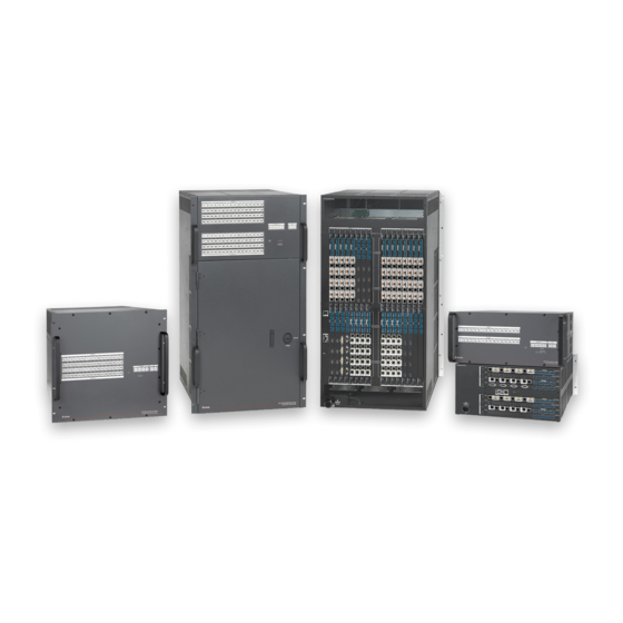
Product Description The configurable and modular XTP II CrossPoint Series matrix switchers route video, audio, bidirectional RS-232 and IR, and Ethernet signals in an integrated XTP system. The types of signals routed depend on the input and output boards installed in the matrix switchers. The number of supported input and output boards include the following: XTP II CrossPoint 1600 —... - Page 11 • Different modes are not compatible with each other. • A color-coded sticker identifies the type of SFP module: orange for multimode and yellow for singlemode. XTP II CrossPoint Series • Introduction...
- Page 12 DTS in combination with the Symbol, the DTS-HD logo, and DTS-HD Master Audio are registered trademarks or trademarks of DTS, Inc. in the United States and/or other countries. © DTS, Inc. All Rights Reserved. XTP II CrossPoint Series • Introduction...
-
Page 13: Other Xtp Devices
XTP System Configuration Software Help File) through the matrix switcher. System Compatibility XTP II CrossPoint series matrix switchers are compatible with other XTP devices, but the maximum video resolution may be limited with different connected XTP models. See the table below for maximum video resolutions and refresh rates for various XTP Systems. -
Page 14: Control Methods
Remote power to XTP transmitters and receivers — Provides power to remote XTP transmitters and receivers over the same STP cable that is used for sending AV signals. This avoids the need for external power supplies at remote endpoints. XTP II CrossPoint Series • Introduction... -
Page 15: Video Features
Authenticates and maintains continuous HDCP encryption between input and output devices to ensure quick and reliable switching in professional AV environments, while enabling simultaneous distribution of a single source signal to one or more displays. XTP II CrossPoint Series • Introduction... - Page 16 NOTE: In North America, the XTP II CrossPoint 6400 plugs into a standard 220 V power outlet. In other regions, it must be wired into a 200-240 VAC junction box. In either case, the outlet or junction box must be installed near the equipment and be easily accessible. XTP II CrossPoint Series • Introduction...
- Page 17 Non-Extron personnel must not attempt to remove the battery. Doing so voids the warranty. • Du personnel ne faisant pas partie d’Extron ne doit pas essayer de retirer la batterie. Cela annulerait la garantie. XTP II CrossPoint Series • Introduction...
-
Page 18: Installation
Installation This section details the installation and configuration of the XTP II CrossPoint Series matrix switchers. Topics in this section include the following: • Installation Overview • Rear Panel Features Input and Output Board Features • • Connection Details Installation Overview The following list describes the basic installation procedure to set up an XTP II CrossPoint Series matrix switcher. -
Page 19: Rear Panel Features
XTP II CrossPoint 6400 Input board slots (see the next page) Output board slots Remote RS-232 and RS-422 connector Ethernet LAN connector Reset button and LED Power connector Figure 2. XTP II CrossPoint Matrix Switcher Rear Panels XTP II CrossPoint Series • Installation... - Page 20 20 A. • Le lieu d’installation doit disposer d’une protection contre les courts- circuits et la surtension de 20 A minimum. • Do NOT use an extension cord. • Ne PAS utiliser de rallonge électrique. XTP II CrossPoint Series • Installation...
-
Page 21: Input And Output Board Connectors
Débranchez l’alimentation du système avant de faire n’importe quelle connexion. NOTE: Audio ground pins on the input and output boards are labeled or . The wiring and function are the same, whichever way the board is labeled. XTP II CrossPoint Series • Installation... -
Page 22: Xtp Interconnection
Amber – blinking Power unavailable but port is enabled Problem with RJ-45 connection Red – blinking For DTP products that support XTP mode: this LED state indicates that a DTP port (with XTP mode enabled) is connected to the XTP port. XTP II CrossPoint Series • Installation... - Page 23 Pass-through LAN connectors Figure 5. Pass-Through LAN Connector Connect a control device or a device to control to a pass-through LAN connector for 10/100BASE-T Ethernet communication (see Twisted Pair Cable Termination for Ethernet Communication on page 21). XTP II CrossPoint Series • Installation...
-
Page 24: Input Connections
Connect a digital video source to a DVI Pro input connector. DVI-D Figure 8. DVI Pro Input Connector NOTE: Although the DVI Pro boards use DVI-I connectors, the matrix switcher handles only DVI-D (digital) video. XTP II CrossPoint Series • Installation... - Page 25 For input cards, see the SIS command on page 52. • For endpoints, see the Audio routing selection for endpoints SIS command. • • The XTP System Configuration Software (see the XTP System Configuration Software Help file) XTP II CrossPoint Series • Installation...
-
Page 26: Output Connection
Connect a Dante-enabled audio processing device to a Dante digital audio transport (AT) LAN connector. 1 (PRI) 2 (SEC) Figure 15. Dante Digital Audio Output Connector NOTE: The Dante Controller software (available at www.extron.com) is required for configuration of the AT ports. XTP II CrossPoint Series • Installation... -
Page 27: Connection Details
Wire color Wire color White-green White-orange White-orange Green Orange Orange White-orange White-green White-green Blue Blue White-blue Blue White-blue Orange Green White-blue White-brown White-brown Green Brown Brown Insert Twisted Pair Wires White-brown RJ-45 Brown Connector XTP II CrossPoint Series • Installation... - Page 28 Do not comb the cable for the first 20 m, where cables are straightened, aligned, and secured in tight bundles. • Loosely place cables and limit the use of tie wraps or hook-and-loop fasteners. • Separate twisted pair cables from AC power cables. XTP II CrossPoint Series • Installation...
-
Page 29: Twisted Pair Cable Termination For Ethernet Communication
Blue Blue Side View Insert Twisted White-blue White-blue White-blue White-blue Pair Wires Green Green Orange Green RJ-45 Connector White-brown White-brown White-brown White-brown Brown Brown Brown Brown Figure 16. RJ-45 Pin Assignment for Ethernet Communication XTP II CrossPoint Series • Installation... -
Page 30: Rs-232 And Ir Over Xtp Communication
Do not tin the wires. Tinned wire does not hold its shape and can become loose over time. • Ne pas étamer les câbles. Les câbles étamés ne sont pas aussi bien fixés dans les borniers à vis captives et pourraient s’arracher. XTP II CrossPoint Series • Installation... -
Page 31: Analog Video Connection
Green return Green return Y return Luma return Video return Blue return Blue return Blue return B-Y return C return Ground Ground Ground EDID/DDC EDID/DDC EDID/DDC H sync C sync V sync EDID/DDC EDID/DDC return return XTP II CrossPoint Series • Installation... -
Page 32: Hdmi Connection
( ATTENTION: • Connect and pull the tie wraps until they are secure. Do not overtighten. • Connectez et tirez les serre-câbles jusqu’à ce qu’ils soient sécurisés. N’effectuez pas de serrage excessif. XTP II CrossPoint Series • Installation... -
Page 33: Analog Audio Connection
See figure 21 for wiring considerations for TRS or RCA connectors. Tip (+) Tip (+) Ring (-) Sleeve ( ) Sleeve ( ) 3.5 mm Stereo Plug Connector RCA Connector (balanced) Figure 21. Typical Audio Connectors XTP II CrossPoint Series • Installation... -
Page 34: Front Panel Operation
Front Panel Operation This section describes the front panel features and operation of the XTP II CrossPoint Series matrix switchers. Topics in this section include the following: Front Panel Features NVRAM modes • • • Front Panel Operation • Reset Modes... - Page 35 Right Redundant LED — Corresponds to the redundant 48 V power supply. • The other XTP II CrossPoint Series matrix switchers have four power supplies. • LEDs 1 and 2 — Correspond to the two primary 12 V power supplies.
-
Page 36: Front Panel Operation
Press the output buttons that correspond to the desired tied output devices to • remove ties. The output buttons blink along with the button. Enter Press the button to accept the pending changes. The buttons return to the Enter regular illumination. XTP II CrossPoint Series • Front Panel Operation... -
Page 37: Front Panel Tie Configuration View
When power is removed and restored, the matrix switcher retains the current configuration and presets. • The matrix switcher does not save the current configration when a preset is recalled unless the current configuration is also saved as a preset. XTP II CrossPoint Series • Front Panel Operation... -
Page 38: Front Panel Analog Audio Input Levels
Highest Numbered Output Button Illumination for Analog Audio Input Levels 1600 Models Other Models Button # Button Color/State Button # Button Color/State Green/Solid Green/Solid Green/Blinking Green/Solid Green/Solid Green/Solid Green/Blinking Green/Solid Green/Solid Green/Solid Green/Blinking Green/Solid Green/Solid Green/Solid XTP II CrossPoint Series • Front Panel Operation... - Page 39 Red/Solid Red/Solid Red/Blinking Red/Solid Red/Solid Red/Solid Red/Blinking Red/Solid Red/Solid Red/Solid Red/Blinking Red/Solid Red/Solid Red/Solid Red/Blinking Red/Solid Red/Solid Red/Solid Press the button to exit the Audio mode. The button stops blinking. Audio Audio XTP II CrossPoint Series • Front Panel Operation...
-
Page 40: Front Panel Output Mutes
Press the button to increase the volume or the button to decrease the View volume. TIP: Hold the Esc or View button to change the volume 3 dB per second. XTP II CrossPoint Series • Front Panel Operation... - Page 41 63 dB Blinking Blinking 53.5% 31 dB Blinking Blinking 0.0% 76 dB Unlit Unlit 52.0% 32 dB Solid Solid Press the button to save the audio settings and exit Audio mode. Audio XTP II CrossPoint Series • Front Panel Operation...
-
Page 42: Front Panel Lockout Modes
Control Buttons I/O Buttons Button Baud Rate Button Protocol Enter 9600 Video RS-232 Preset 19200 Audio RS-422 View 38400 115200 Press an output button to save the settings and exit configuration mode. XTP II CrossPoint Series • Front Panel Operation... -
Page 43: Front Panel Reset
(see on the previous page). Press the button to clear pending actions. Hold the buttons simultaneously until the front panel buttons Input 1 Input 2 change in illumination (about 2 seconds). XTP II CrossPoint Series • Front Panel Operation... -
Page 44: Analog Audio Optimization
NOTE: Ensure the captive screw connector used for insertion is physically connected to another device. To enable XTP ports for either insertion method, use the XTP System Configuration Software (see the XTP System Configuration Software Help file). XTP II CrossPoint Series • Front Panel Operation... -
Page 45: Ethernet To Rs-232 Insertion
To change the starting point, use the XTP System Configuration Software (see the XTP System Configuration Software Help file). NOTE: Ensure the RS-232 protocol matches the connected device. To do this, use the XTP System Configuration Software (see the XTP System Configuration Software Help file). XTP II CrossPoint Series • Front Panel Operation... -
Page 46: Captive Screw Insertion
The rear panel Remote RS-232 and RS-422 connector and all input serial ports in the matrix swticher are numbered sequentially (see the table on the next page). Output serial ports start at 34 or 64 and continue on sequentially. XTP II CrossPoint Series • Front Panel Operation... - Page 47 2110 Output 62 2126 Output 15 2047 2079 Output 31 2063 2095 Output 47 2111 Output 63 2127 Output 16 2048 2080 Output 32 2064 2096 Output 48 2112 Output 64 2128 XTP II CrossPoint Series • Front Panel Operation...
-
Page 48: Nvram Modes
NOTE: • The user can still configure the endpoints from the matrix in this mode. • Projectors and other XTP compatible devices work in this mode as well. XTP II CrossPoint Series • Front Panel Operation... -
Page 49: Reset Modes
• (mode 5) Then, press the button again configuration. Reset values. momentarily (<1 second). • Uploaded files are removed. The Reset LED blinks four times • in quick succession during the reset. XTP II CrossPoint Series • Front Panel Operation... -
Page 50: Troubleshooting
(solid) Analog audio input Red (solid or Red (solid) attenuation blinks) (blinks) Analog audio input Green (solid or Red (solid) gain blinks) (blinks) Red (solid or Output volume Red (solid) blinks) (solid) XTP II CrossPoint Series • Front Panel Operation... - Page 51 RS-232 (blinks) (blinks) 9600 baud rate for RS-422 (blinks) (blinks) 19200 baud rate for RS-422 (blinks (blinks) 38400 baud rate for RS-422 (blinks) (blinks) 115200 baud rate for RS-422 (blinks) (blinks) XTP II CrossPoint Series • Front Panel Operation...
-
Page 52: Sis Configuration And Control
SIS Configuration and Control This section describes the operation of the XTP II CrossPoint Series Matrix Switchers via Simple Instruction Set (SIS) commands. It includes commands for basic, everyday functions of the matrix switcher frame, as well as IP and Remote Port Commands to control and monitor the IP interface and Remote RS-232/RS-422 port of the matrix switcher. -
Page 53: Ethernet Connection Considerations
Patch (straight-through) cable — Connection of the XTP II CrossPoint Series matrix switcher to an Ethernet LAN. To connect to the XTP II CrossPoint Series matrix switcher, open a TCP socket to port 23 using the IP address of the matrix switcher. -
Page 54: Sis Overview
When a valid password is entered, the matrix switcher responds with one of the following: • Login Administrator • Login User response represents administrator access and the Login Administrator Login response represents user access. User XTP II CrossPoint Series • SIS Configuration and Control... - Page 55 To receive notices of changes made to the matrix switcher from other telnet sockets or a Set verbose mode serial connection, set the verbose mode to modes 1 or 3 (see the command on page 65). The notices appear as SIS responses. XTP II CrossPoint Series • SIS Configuration and Control...
-
Page 56: Command And Response Table Overview
The matrix switcher does not accept the following characters for names or passwords: • (space character, acceptable for names) + - , @ = ‘ [ ] { } < > ` “ ; : | \ ? XTP II CrossPoint Series • SIS Configuration and Control... - Page 57 = Invalid command for the current • = Invalid event number configuration • = Bad filename or file not found • = timeout (caused only by direct write or global presets) XTP II CrossPoint Series • SIS Configuration and Control...
-
Page 58: Command And Response Tables
2 = HDMI input 2 3 = HDMI input 3 1. If the “View follow-all” command is sent to an output with a break-away tie, the switcher responds with error message E13 XTP II CrossPoint Series • SIS Configuration and Control... -
Page 59: Presets
0 = No mutes, 1 = Video mute, 2 = HDMI/SPDIF Audio Mute, 3 = Video and HDMI/SPDIF Audio Mute, 4 = Analog audio, 5 = Video and Analog audio mute, 6 = All audio mute, 7 = Video and audio mute XTP II CrossPoint Series • SIS Configuration and Control... -
Page 60: Audio Configuration And Adjustment
-18 to +24 (43 steps of gain or attenuation) (default = 0 dB) X31% = Audio attenuation (input) 1 - 18 (1 dB per step) X34# = (0) Auto, (1) Digital 2-channel audio, (2) Local 2-channel audio XTP II CrossPoint Series • SIS Configuration and Control... -
Page 61: Sdi Audio
X31& = SDI audio channel (AES channel pairs 1 or 2) X31* = SDI audio group (AES channel group 1 to 4) X34# = (0) Auto, (1) Digital 2-channel audio, (2) Local 2-channel audio XTP II CrossPoint Series • SIS Configuration and Control... -
Page 62: Vga Input Configuration And Adjustment
01 to maximum number of inputs for your switcher model X30@ = Input number on transmitter X32) = Image reset status 0 = disable, 1 = enable X37@ = Preset number 1 - 6 XTP II CrossPoint Series • SIS Configuration and Control... -
Page 63: Scaler Adjustment
01 to maximum number of inputs for your switcher model X30@ = Input number on transmitter X34) = 0 = No source connected; 1 = Source is HDCP compliant; 2 = Source is not HDCP compliant XTP II CrossPoint Series • SIS Configuration and Control... -
Page 64: Signal Status
00 to maximum number of inputs (input = 0 untie) X30( = Video mute status 0 = Off, 1 = On X32! = Audio mute status 0 = Off, 1 = On XTP II CrossPoint Series • SIS Configuration and Control... -
Page 65: Xtp Setup Parameters
2 = Power available for the endpoint, but disabled 3 = No power available for the endpoint, but enabled 4 = Fault X39% = Error status 0 = Power status OK 1 = Power supply fault XTP II CrossPoint Series • SIS Configuration and Control... -
Page 66: Xtp Relay Control
View file directory E DF } See below: List user-supplied files. Web browser Var•file•=•new•array•(); File•[1]•=•‘filename1,date1,filesize1‘; File•[2]•=•‘filename2,date2,filesize2‘; File•[3]•=•‘filename3,date3,filesize3‘; • • • • File•[n]•=•‘filenamen,daten,filesizen‘; File•[n+1]•=•# of•Bytes•Left Erase user-supplied web E filenameEF } Del•filename ] pages/files XTP II CrossPoint Series • SIS Configuration and Control... -
Page 67: Information Requests
O = XTP CP 4o Fiber 4K X = No board installed X4( = Firmware version number to second decimal place (x.xx) X5) = Verbose firmware version-description-upload date/time (see the Query firmware version (verbose) command, above). XTP II CrossPoint Series • SIS Configuration and Control... - Page 68 0TEST Tst00 X4@] View test pattern status TEST KEY: X4@ = Test pattern and resolution = Disable (default) Color bars Black screen 720p, 50 Hz 720p, 60 Hz 1080p, 60 Hz XTP II CrossPoint Series • SIS Configuration and Control...
-
Page 69: Lockout Modes
10 maximum (each can have up to 10 presets (X31@) assigned) X31! = Global preset # (0 = current ties for system in view) [16-32-64 max] X31@ = Room preset # 10 maximum (0 = current configuration) XTP II CrossPoint Series • SIS Configuration and Control... -
Page 70: Ip- And Remote Port-Specific Sis Commands
NOTE: The @ character is acceptable only as the lead-in to the domain name (such as @extron.com = E-mail account = e-mail recipient 1, = 2, = 3,... = recipient 8) = E-mail address Typical e-mail address format (for example: nnn@xxx.com XTP II CrossPoint Series • SIS Configuration and Control... - Page 71 = default) 0000 1000 0000 = Time (in 10 MS increments) (for example, = 100 MS) 32767 to wait for characters = Time (in 10 MS increments) = default) 32767 between characters XTP II CrossPoint Series • SIS Configuration and Control...
- Page 72 EX6& , X7! , X7) CM } Ipm X6& , X7! , X7) ,, ] Set mail server, domain name E CM } X6& , X7! , X7) ,, ] Read mail server, domain name XTP II CrossPoint Series • SIS Configuration and Control...
- Page 73 Pti0* X9@] Read current port timeout E 0TC } X9@] E 1* X9@ TC } Pti1* X9@] Configure global IP port timeout X9@] Read global IP port timeout E 1TC } XTP II CrossPoint Series • SIS Configuration and Control...
-
Page 74: Html Operation
HTML Operation The XTP II CrossPoint Series can be remotely controlled via: • The XTP System Configuration Software (see the XTP System Configuration Software Help file, available at www.extron.com) • SIS commands (see SIS Configuration and Control on page 44) Built-in HTML pages (see below) •... -
Page 75: Download The Startup Page
If neither of the above conditions is true, the matrix switcher downloads the • factory-installed default startup page, “ ” (see figure 26 on the nortxe_index.html next page), also known as the page. System Status XTP II CrossPoint Series • HTML Operation... -
Page 76: Status Tab
System Status Page page periodically refreshes itself to reflect the latest status of the matrix System Status switcher components. If a value changes, the display shows the change in status the next time it refreshes. XTP II CrossPoint Series • HTML Operation... -
Page 77: Dsvp Page
(see figure 28) provides the HDCP status of inputs to and outputs from the HDCP matrix switcher. Access the page from the page by clicking HDCP System Status DSVP link on either the page. HDCP System Status DSVP Figure 28. HDCP Page XTP II CrossPoint Series • HTML Operation... -
Page 78: Configuration Tab
Configuration Tab System Settings Page The XTP II CrossPoint Series matrix switcher downloads the page (see System Settings figure 29) when you click the tab ( ). The screen consists of fields in which you Configuration can view and edit IP administration and system settings. You can access the... - Page 79 Part Number field field ( ) identifies the part number of your matrix switcher. This field is Part Number £ hardcoded in the matrix switcher and cannot be changed. XTP II CrossPoint Series • HTML Operation...
- Page 80 When is turned off, the matrix switcher does not Daylight Saving adjust its time reference. Click the button ( Submit XTP II CrossPoint Series • HTML Operation...
-
Page 81: Passwords Page
Reset an existing password so that no password is required as follows: Replace any existing password by entering a single space character in the Password fields (see figure 31, Re-enter Password Click the button ( Submit XTP II CrossPoint Series • HTML Operation... -
Page 82: Email Settings Page
Valid IP addresses consist of four 1-, 2-, or 3-digit numeric octets separated by dots (periods). Each field can be numbered from 000 through 255. Leading zeroes, up to three digits total per field, are optional. Values of 256 and above are invalid. XTP II CrossPoint Series • HTML Operation... - Page 83 The five fields ( ) identify the e-mail addresses of the personnel to whom Email Address the XTP II CrossPoint Series matrix switcher e-mails notification of its failure and repair status. Standard e-mail address conventions ( ) apply. nnnnn@xxx.com The check boxes and drop boxes associated with each address field permit the operator to specify specific criteria under which the matrix switcher will e-mail recipients.
-
Page 84: Firmware Upgrade Page
NOTE: The firmware release notes are a PDF file that provides details about the changes between different firmware versions. The file can be downloaded from the same page as the firmware. Submit any required information to start the download. Note where the file is saved. XTP II CrossPoint Series • HTML Operation... - Page 85 Updating Firmware Connect the PC to the XTP II CrossPoint Series matrix switcher via the LAN port of the matrix switcher. Access the XTP II CrossPoint Series matrix switcher using HTML pages (see Download the Startup Page on page 67). Click the...
-
Page 86: File Management Tab
NOTE: If you want one of the pages that you create and upload to be the default startup page, name that file “index.html.” Click the button ( ). The file or files that you selected appear in the list. Upload File XTP II CrossPoint Series • HTML Operation... -
Page 87: Control Tab
• To tie an input to all outputs, click that input number. Click the button ( ) to make the configuration changes or the button to Take Cancel abandon the configuration changes. XTP II CrossPoint Series • HTML Operation... -
Page 88: Maintenance And Modifications
Maintenance and Modifications This section covers XTP II CrossPoint Series matrix switcher topics, including: Mounting the Matrix Switcher • • Battery and Power Precautions Removing and Installing an Input or Output Board or Blank Plate • • Removing and Installing a Power Supply (XTP II CrossPoint 6400) •... -
Page 89: Mounting Instructions
Removing and Installing an Input or Output Board or Blank Plate Circuit boards can be replaced for fault correction. They can be added or removed to increase or decrease the Input or output configuration (size) of the XTP II CrossPoint Series matrix switcher. -
Page 90: Installing An Input Or Output Board Or Blank Plate
Gently seat the board or panel in the backplane. Use a screwdriver to tighten the captive screws that lock the board or panel in place. XTP II CrossPoint Series • Maintenance and Modifications... -
Page 91: Removing And Installing A Power Supply Assembly (Xtp Ii Crosspoint 6400)
) and pull the assembly from the cabinet. If you are not going to install a replacement power supply immediately, close the power supply cabinet door and turn the door fastener counter-clockwise to lock it shut. XTP II CrossPoint Series • Maintenance and Modifications... -
Page 92: Installing A Power Supply Assembly
Slide the power supply to the left until it contacts the left wall. Use an Extron Tweeker or small screwdriver to install the locking screw. Close the power supply cabinet door and turn the door fastener counter-clockwise to lock it shut. XTP II CrossPoint Series • Maintenance and Modifications... -
Page 93: Replacing And Terminating The Power Cable (Xtp Ii Crosspoint 6400)
Connect the wires to the appropriate prongs of the power plug and assemble the plug, as detailed in the instructions that accompanied the plug. Plug the power cord into the 220 VAC power outlet. XTP II CrossPoint Series • Maintenance and Modifications... -
Page 94: Replacing The Cable
). Remove the ground strap. Remove and retain the two screws that secure the matrix switcher power distribution box panel in place ( ). Lift the power box from the matrix switcher. XTP II CrossPoint Series • Maintenance and Modifications... - Page 95 Adjust the length of the cables inside the power distribution box until they reach the terminal block and ground stud with minimal excess. Tighten the cable clamp. XTP II CrossPoint Series • Maintenance and Modifications...
-
Page 96: Removing And Installing Button Labels
The Extron Button Label Generator is available on the Extron website, www.extron.com, under the tab. Click the link (see figure 47 on the next page), and Download Software download and install the program on your PC. XTP II CrossPoint Series • Maintenance and Modifications... - Page 97 The installation also places the Button Label Generator icon into a group or folder named “Extron Electronics.” Using the Button-Label Generator software Click Start > Programs > Extron Electronics > Button Label Generator > . The Button-Label Generator window opens (see figure 48). Button Label Generator Figure 48.
-
Page 98: Making Labels From Paper Templates
Align the tabs on the base of the matrix switcher with the notches on the diffuser plate. Gently, but firmly, press the reassembled button into place in the front panel of the matrix switcher. Repeat steps 1 to 7 as needed to relabel other buttons. XTP II CrossPoint Series • Maintenance and Modifications... - Page 99 XTP II CrossPoint Series • Maintenance and Modifications...
-
Page 100: Ethernet Connection
If the address has not been changed, the factory-specified default is 192.168.254.254. Ping can also be used to test the Ethernet link to the XTP II CrossPoint Series matrix switcher. XTP II CrossPoint Series • Ethernet Connection... -
Page 101: Pinging To Determine The Extron Ip Address
The ping utility is available at the Command prompt. Ping tests the Ethernet interface between the computer and the XTP II CrossPoint Series matrix switcher. Ping can also be used to determine the actual numeric IP address from an alias and to determine the Web address. -
Page 102: Use Via The Arp Command
Obtain a valid IP address for the XTP II CrossPoint Series matrix switcher from your network administrator. Obtain the MAC address (UID #) of the XTP II CrossPoint Series matrix switcher from the label on its rear panel. The MAC address should have this format: 00-05-A6-xx-xx-xx. -
Page 103: Connecting As A Telnet Client
Connecting as a Telnet Client The Microsoft Telnet utility is available from the prompt. Telnet allows you to input SIS commands to the XTP II CrossPoint Series matrix switcher from the PC via the Ethernet link and the LAN. Access the... - Page 104 <Enter> at the Telnet prompt. If you are connected to the XTP II CrossPoint Series matrix switcher and need to access the Telnet prompt to turn analog echo off, type the Escape character <Ctrl>+<]> Set carriage return-line feed...
-
Page 105: Subnetting - A Primer
IP addresses in common) is necessary in order to understand the interaction of the XTP II CrossPoint Series matrix switcher and the mail server gateway. To understand subnetting at the level required to install and operate the XTP II CrossPoint Series matrix switcher, you must understand the concepts of a gateway, analog and remote devices, IP addresses and octets, and subnet masks and octets. -
Page 106: Determining Whether Devices Are On The Same Subnet
192.168.2.25 190.190.2.25 192.190.2.25 ≠.≠.X.X Match?: =.=.X.X — Match — No match =.≠.X.X — No match subnet) subnet) subnet) (Same (Different (Different Figure 56. Comparing the IP Addresses of the Analog and Remote Devices XTP II CrossPoint Series • Ethernet Connection... -
Page 107: Reference Information
Worksheet Example 1: System Equipment Inputs include PCs, an audio CD player, cameras, and an Extron VTG 400DVI. Output devices include monitors, projectors, a stereo, a VCR for recording presentations, and a DA. XTP II CrossPoint Series • Reference Information... -
Page 108: Worksheet Example 2: Daily Configuration
Classical music from the CD player (input 5) is: Played in the background in the main hall on sound system #2 (output 5) • Played in the lobby via a distribution amplifier (output 8) • XTP II CrossPoint Series • Reference Information... -
Page 109: Worksheet Example 3: Test Configuration
Video: Audio: Fill in the preset number and use colors, dashes, etc., to make connecting lines. Indicate if the configuration is for video, audio, or both. Figure 59. Worksheet Example 3: Test Configuration XTP II CrossPoint Series • Reference Information... -
Page 110: Xtp Ii Crosspoint 6400 Matrix Switchers Configuration Worksheet
XTP II CrossPoint 6400 Matrix Switchers Configuration Worksheet XTP II CrossPoint Series • Reference Information... -
Page 111: Xtp Ii Crosspoint 3200 Matrix Switchers Configuration Worksheet
XTP II CrossPoint 3200 Matrix Switchers Configuration Worksheet XTP II CrossPoint Series • Reference Information... -
Page 112: Xtp Ii Crosspoint 1600 Matrix Switchers Configuration Worksheet
XTP II CrossPoint 1600 Matrix Switchers Configuration Worksheet XTP II CrossPoint Series • Reference Information... - Page 113 In the event of malfunction during the warranty period attributable directly to faulty workmanship and/ or materials, Extron Electronics will, at its option, repair or replace said products or components, to whatever extent it shall deem necessary to restore said product to proper operating condition, provided that it is returned within the...
Need help?
Do you have a question about the XTP II CrossPoint Series and is the answer not in the manual?
Questions and answers