Table of Contents
Advertisement
Quick Links
Advertisement
Table of Contents

Related Manuals for Extron electronics CrossPoint 300 84


Summary of Contents for Extron electronics CrossPoint 300 84
- Page 1 CrossPoint 300 Series Matrix Switchers 68-521-10 Rev. B 03 07...
- Page 2 Precautions Safety Instructions • English Warning Power sources • This equipment should be operated only from the power source indicated on the product. This This symbol is intended to alert the user of important operating and maintenance equipment is intended to be used with a main power system with a grounded (neutral) conductor. The (servicing) instructions in the literature provided with the equipment.
-
Page 3: Front Panel Controls
Quick Start — CrossPoint 300 Matrix Switchers Installation Step 7 Plug the switcher and input and output devices Step 1 into a grounded AC source, and turn on the input If desired, mount the switcher in a rack. and output devices. Step 2 Definitions Turn off power to the input and output devices,... - Page 4 Quick Start — CrossPoint 300 Matrix Switchers, cont’d RGBHV and Audio buttons select/deselect Save or recall a preset video and/or audio. The Audio LED blinks to 1. Save a preset — Press and hold the Preset indicate audio breakaway. button for 2 seconds. The Audio button and LED are present on Recall a preset —...
-
Page 5: Table Of Contents
Table of Contents Chapter 1 • Introduction ....................... 1-1 About this Manual ......................1-2 About the Matrix Switchers ..................1-2 Definitions ..........................1-3 Features ........................... 1-4 Chapter 2 • Installation ......................2-1 Mounting the Switcher ....................2-2 UL requirements ........................ 2-2 Mounting instructions ....................... - Page 6 Table of Contents, cont’d Setting the front panel locks (Executive modes) ............3-34 ......3-35 Selecting Lock mode 2 or toggling between mode 2 and mode 0 ......3-35 Selecting Lock mode 2 or toggling between mode 2 and mode 1 Performing a system reset from the front panel ............
- Page 7 Chapter 5 • Matrix Software ....................5-1 Matrix Switchers Control Program ................5-2 Installing the software ...................... 5-2 Using the software ......................5-3 Updating the firmware ..................... 5-5 Windows buttons, drop boxes, and trash ................ 5-8 Windows menus ......................... 5-8 File menu ........................
- Page 8 Table of Contents, cont’d 68-521-10 Rev. B 03 07 All trademarks mentioned in this manual are the properties of their respective owners. CrossPoint 300 Matrix Switchers • Table of Contents...
-
Page 9: Chapter 1 • Introduction
CrossPoint 300 Matrix Switchers Chapter One Introduction About this Manual About the Matrix Switchers Definitions Features... -
Page 10: About This Manual
The matrix switchers are housed in rack-mountable, metal enclosures with rack ears to fit in a 19" rack. • The CrossPoint 300 84, 88, 124, and 128 are in a 3U-high enclosure. • The CrossPoint 300 816, 168, 1212, and 1616 are in a 6U-high enclosure. -
Page 11: Definitions
Classroom 101 Classroom 102 Extron CrossPoint 300 128 HVA Matrix Switcher 8 Outputs Extron DVS 304 Scaler RS-2 /B-Y RESET LINK /R-Y ,B-Y/Y C/VID RGB/ R-Y,Y /VID Y,B-Y /R-Y, Extron 100-24 50/60 VSC 700 Scan Converter 12 Inputs Extron DVS 304 Scaler RS-2 /B-Y... -
Page 12: Features
Introduction, cont’d Features Video — All switchers input and output wideband RGBHV or RGBS video on female BNC connectors. They can also switch RGsB, RsGsBs, component/ HDTV, S-video, or composite video. Bandwidth — The CrossPoint 300 Series switchers provide a minimum of 300 MHz (-3 dB) video bandwidth, fully loaded. - Page 13 Operational flexibility — Operations such as input/output selection, setting of presets, and adjustment of audio levels can be performed on the front panel or via either serial port. The serial ports also allow remote control via a PC or control system. •...
- Page 14 Introduction, cont’d This page was intentionally left blank. CrossPoint 300 Matrix Switchers • Introduction...
-
Page 15: Chapter 2 • Installation
CrossPoint 300 Matrix Switchers Chapter Two Installation Mounting the Switcher Connections and Rear Panel Features Front Panel Configuration Port... -
Page 16: Mounting The Switcher
The amount of vertical rack space required for each switcher is as follows: • The CrossPoint 300 84, 88, 124, and 128 are in a 3U-high enclosure. • The CrossPoint 300 816, 168, 1212, and 1616 are in a 6U-high enclosure. -
Page 17: Connections And Rear Panel Features
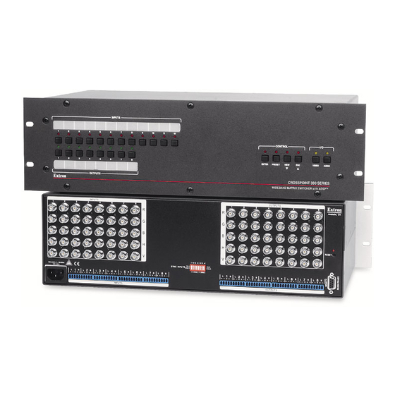
Figure 2-1 shows the CrossPoint 300 128 HVA. The CrossPoint 300 84, 88, and 124 are housed in the same 3U enclosure, but have fewer input and/or output connectors to accommodate their smaller matrix sizes. -
Page 18: Rgbhv Input And Output
Installation, cont’d RGBHV input and output The switcher can connect to up to as many as 16 RGBHV video and/or stereo audio devices, depending on the model. The switcher can output to as many as 16 video and/or audio outputs, depending on the model. - Page 19 See figure 2-4 to identify the tip, ring, and sleeve when you are making connections for the switcher from existing audio cables. A mono audio connector consists of the tip and sleeve. A stereo audio connector consists of the tip, ring and sleeve. The ring, tip, and sleeve wires are also shown on the captive screw audio connector diagrams, figure 2-3 and figure 2-5.
-
Page 20: Remote (Rs-232/Rs-422) Port
Installation, cont’d Remote (RS-232/RS-422) port RS-232/RS-422 Remote connector — Connect a host device, such as a computer, touch panel control, or RS-232 capable PDA to the switcher via this 9-pin D connector for serial RS-232/RS-422 control (figure 2-6). RS-232 Function RS-422 Function —... -
Page 21: Sync Termination Switches
Sync termination switches Sync termination switches — The CrossPoint 300 matrix switchers have sync termination switches on the rear panel for inputs 1 through 4 (figure 2-7). The switches provide a way to condition non-TTL sync levels greater than 5 Vp-p, enabling the sync to be properly passed from input to selected output(s). -
Page 22: Front Panel Configuration Port
Installation, cont’d Front Panel Configuration Port CONTROL CONFIG ENTER PRESET VIEW RGBHV AUDIO CROSSPOINT 300 SERIES WIDEBAND MATRIX SWITCHER with ADSP™ Figure 2-8 — Front panel configuration port Configuration port — This 2.5 mm mini stereo jack serves the same serial communications function as the rear panel Remote port, but it is easier to access than the rear port after the matrix switcher has been installed and cabled. - Page 23 This port is RS-232 only, with its default protocols as follows: • 9600 baud • no parity • 8 data bits • 1 stop bit • no flow control The maximum distances from the matrix switcher to the controlling device can vary up to 200 feet (61 m).
- Page 24 Installation, cont’d 2-10 CrossPoint 300 Matrix Switchers • Installation...
-
Page 25: Chapter 3 • Operation
CrossPoint 300 Matrix Switchers Chapter Three Operation Front Panel Controls and Indicators Front Panel Operations Rear Panel Operations Optimizing the Audio (HVA Switchers) Troubleshooting Configuration Worksheets... -
Page 26: Front Panel Controls And Indicators
While the number of inputs and outputs varies depending on the size of the matrix, there are only two front panel arrangements. • The CrossPoint 300 84, 88, 124, and 128 have 12 input buttons and 8 output buttons (figure 3-1). •... -
Page 27: Definitions
Definitions The following terms, which apply to Extron matrix switchers, are used throughout this manual: Tie — An input-to-output connection. Set of ties — An input tied to two or more outputs. (An output can never be tied to more than one input.) Configuration —... -
Page 28: Control Buttons
Operation, cont’d Input and output label windows — These translucent panels can be removed and replaced to insert labels behind the panels. To remove a panel, insert the Phillips-head end of a Tweeker or small Phillips-head screwdriver into the hole in one end of the panel, and gently slide the tab at the edge of the panel out of the recess in the switcher housing. - Page 29 Preset button and LED — The Preset button and LED have two primary functions (•) and three secondary ( ) functions: • Activates Save Preset mode to save a configuration as a preset and Recall Preset mode to activate a previously-defined preset. •...
-
Page 30: I/O Controls
Operation, cont’d Esc ( ) button and LED — The Esc ( ) button and LED have two primary functions (•) and six secondary ( ) functions: • Cancels operations or selections in progress and resets the front panel button indicators. The Esc ( ) button does not reset the current configuration, the RGBHV button and Audio selection button, any presets, or any audio gain or... -
Page 31: Front Panel Operations
Audio button and LED — The Audio button and LED have two primary functions (•) and five secondary ( ) functions • (HVA models only) Selects and deselects audio for a configuration that is being created or viewed. • (HVA models only) Lights to indicate that audio is available for configuration or viewing. -
Page 32: Power Indications
Operation, cont’d Power indications Power is applied when the power cord is connected to an AC source. The switcher performs a self-test that flashes the front panel button indicators and then turns them off. For HVA models, an error-free power up self-test sequence leaves the RGBHV LED and the Audio LED on, and all other LEDs unlit. -
Page 33: Example 1: Creating A Set Of Video And Audio Ties
Example 1: Creating a set of video and audio ties The following steps show an example in which input 5 is tied to outputs 3, 4, and 8. The steps show the front panel indications that result from your actions. This example assumes that there are no ties in the current configuration. -
Page 34: Example 2: Adding A Tie To A Set Of Video And Audio Ties
Operation, cont’d Press and release the Output 3, Output 4, and Output 8 buttons. The LEDs blink to indicate that the selected RGBHV and audio input will be tied to these outputs. ENTER PRESET OUTPUTS The Enter LED blinks to indicate the need to confirm the change. - Page 35 This example assumes that you have performed example 1. Press and release the Esc button (figure 3-10). Press the Esc button to clear all selections. CONTROL The LED blinks once. ENTER PRESET VIEW Figure 3-10 — Clear all selections To select video only for the tie, if necessary, press and release the RGBHV button and/or Audio button (figure 3-11).
-
Page 36: Example 3: Removing A Tie From A Set Of Video And Audio Ties
Operation, cont’d Press and release the Output 1 button. The Enter LED blinks to indicate The LED blinks to indicate that the selected the need to confirm the change. RGBHV input will be tied to this output. ENTER PRESET OUTPUTS Figure 3-13 —... - Page 37 This example assumes that you have performed example 1 and example 2. Press and release the Esc button (figure 3-16). Press the Esc button to clear all selections. CONTROL The LED blinks once. ENTER PRESET VIEW Figure 3-16 — Clear all selections To select audio only for the tie, if necessary, press and release the RGBHV button and/or Audio button (figure 3-17).
- Page 38 Operation, cont’d Press and release the Output 4 button. The Enter LED blinks to indicate the need to confirm the change. The LED blinks to indicate that the selected RGBHV output will be untied. ENTER PRESET OUTPUTS Figure 3-19 — Deselect the output Press and release the Enter button (figure 3-20).
-
Page 39: Viewing A Configuration
Viewing a configuration The current configuration can be viewed using the front panel buttons. The View-only mode prevents inadvertent changes to the current configuration. View-only mode also provides a way to mute video and audio outputs (see “Muting and unmuting video and/or audio” on page 3-18. View the current configuration as follows: Press the Esc button to clear any input LEDs, output LEDs, or control LEDs that are lit. - Page 40 Operation, cont’d Press and release the View button to enter View-only mode. The View LED lights. To select both video and audio for viewing, if necessary, press and release the RGBHV button and the Audio button (figure 3-23). In this example, the Audio LED blinks to indicate audio breakaway (assuming you have performed example 1, 2, and 3).
- Page 41 Press and release the RGBHV button to deselect RGBHV (figure 3-25). The output buttons for outputs that are tied to Input 5 light to indicate audio ties (audio breakaway). RGBHV AUDIO Press the RGBHV The Audio LED button to delesect it. remains lit to indicate that only audio is The LED is unlit...
-
Page 42: Muting And Unmuting Video And/Or Audio
Operation, cont’d Muting and unmuting video and/or audio Individual outputs can be muted or unmuted as follows: Mutes are protected when front panel lock mode 2 is selected. You can view the status of the output (muted or unmuted) in lock mode 2 but not change it from the front panel. - Page 43 To select both video and audio for viewing and muting, if necessary, press and release the RGBHV button and the Audio button (figure 3-29). This example shows the indications that the front panel displays if example 1, example 2, and example 3 have been completed. In this example, the Audio LED blinks to indicate audio breakaway (assuming you have performed example 1, 2, and 3).
-
Page 44: Using Global Presets
Operation, cont’d Press and hold the Output 3 button and the Output 4 button (figure 3-31) for approximately 2 seconds until the LEDs light steadily. The output 3 and output 4 video and audio signals are unmuted. The LEDs stop blinking and light to indicate that One at a time, press and hold the Output 3 button the RGBHV and audio outputs are unmuted. -
Page 45: Example 6: Saving A Preset
Example 6: Saving a preset The following steps show an example in which the current configuration is saved as a preset in a CrossPoint 300 1616. The steps show the front panel indications that result from your actions. Press and release the Esc button (figure 3-33). Press the Esc button to clear all selections. -
Page 46: Example 7: Recalling A Preset
Example 7: Recalling a preset The following steps show an example in which a preset is recalled to become the current configuration in a CrossPoint 300 84. The steps show the front panel indications that result from your actions. Press and release the Esc button (figure 3-37). - Page 47 Press and release the Output 1 button (figure 3-39). Press and release the Output 1 button. The LED blinks to indicate that this preset number is selected but not recalled. CONTROL ENTER PRESET VIEW Preset 13 Preset 14 Preset 15 Preset 16 The Enter LED blinks to indicate the need to recall the preset.
-
Page 48: Viewing And Adjusting The Input Audio Level (Hva Models)
Operation, cont’d Viewing and adjusting the input audio level (HVA models) On HVA models, the audio level of each input can be displayed and adjusted through a range of -18 dB to +24 dB to ensure that there is no noticeable volume difference among sources (figure 3-41). -
Page 49: Example 8: Viewing And Adjusting An Input Audio Level
Example 8: Viewing and adjusting an input audio level The following steps show an example in which an audio level is viewed and adjusted. The steps show the front panel indications that result from your actions. Audio gain and attenuation is displayed differently on different models. See the table on page 3-26. - Page 50 Operation, cont’d Audio gain and attenuation settings CrossPoint 300 84, 88, 124, 128 HVA CrossPoint 300 816, 168, 1616 HVA Output LED Output LED View Esc View Esc = on, = blinking fast, = blinking slowly, = off 3-26 CrossPoint 300 Matrix Switchers • Operation...
- Page 51 Press and release the input 5 button (figure 3-44). Figure 3-44 shows the current level (+8 dB) displayed on an 8-ouput-LED switcher, such as a CrossPoint 300 128 HV A. Press and release the Input 5 button. The LED lights. VIEW OUTPUTS The View and Esc LEDs display...
- Page 52 Note that the View LED is now lit to indicate a negative level. Figure 3-46 shows the adjusted level (–1 dB) displayed on an 8-ouput-LED switcher, such as a CrossPoint 300 84 HV A. Press the View button to decrease the input audio level by 1 dB per button push.
-
Page 53: Viewing And Adjusting The Output Volume (Hva Models)
Press and release the Audio button (figure 3-48). Press the Audio button to exit audio mode. All input LEDs and output LEDs return to the unlit state. RGBHV AUDIO RGBHV AUDIO The Audio LED stops blinking and lights steadily. The RGBHV button lights. Figure 3-48 —... -
Page 54: Reading The Displayed Value
Operation, cont’d Reading the displayed value This section is a detailed look at reading the output volume display on the switcher’s front panel. If you do not need to read the exact value of the volume setting, skip this section. There are 65 steps of volume attenuation, with 1 dB per step (button push), except for 0-to-1, which is 22dB. - Page 55 Audio output volume settings CrossPoint 300 84, 88, 124, 128 HVA CrossPoint 300 816, 168, 1616 HVA Output dB of Input LED Output dB of Input LED volume attenuation volume attenuation 5.5% 5.5% 8.5% 8.5% 11.5% 11.5% 14.5% 14.5% 17.5% 17.5%...
-
Page 56: Example 9: Viewing And Adjusting An Output Volume Level
Operation, cont’d For example: When lit steadily, the Input 3 button indicates the following, depending on the number of input buttons the switcher has: Switchers with 12 input buttons — 47 dB of attenuation when compared to the Input 3 LED blinking quickly (48 dB to 50 dB of attenuation). The blinking Input 4 LED (45 dB to 46 dB of attenuation) is at least 2 dB less than the fast blinking Input 3 LED (48 dB –... - Page 57 Press and release the output 1 button (figure 3-51). The input LEDs display the selected output's audio volume level. In this example, the lit input buttons indicate 40 to 41.5 percent of the applied audio input. The unlit input buttons indicate an audio volume attenuation of 39 dB to 40 dB. Press and release the Output 1 button.
-
Page 58: Setting The Front Panel Locks (Executive Modes)
Operation, cont’d Figure 3-54 shows the same volume (61%) as in figure 3-53, but displayed on a 16-output-button switcher, such as a CrossPoint 300 1616 HVA. In this example, the input buttons display an audio gain level of –26 dB. = Lit LED, = Unlit LED, = Slow blinking LED... -
Page 59: Selecting Lock Mode 2 Or Toggling Between Mode 2 And Mode 0
Basic features consist of: Making ties Saving and recalling presets Setting input audio gain and attenuation Changing Lock modes Advanced features consist of: Setting video and audio output mutes Setting audio output volume Setting the rear panel remote port protocol and baud rate The switcher ships from the factory in Lock mode 2. -
Page 60: Performing A System Reset From The Front Panel
Operation, cont’d Performing a system reset from the front panel The front panel reset is identical to the rear panel system reset (see “Performing a system reset from the rear panel” on page 3-39) and to the ZXXX command (see chapter 4, “Programmer’s Guide”). A system reset: •... -
Page 61: Selecting The Rear Panel Remote Port Protocol And Baud Rate
Selecting the rear panel Remote port protocol and baud rate The Remote port settings are protected when front panel lock mode 2 is selected. You can view the settings in lock mode 2 but not adjust them from the front panel. The matrix switcher can support either RS-232 or RS-422 serial communication protocol, and operate at 9600, 19200, 38400, and 115200 baud rates. - Page 62 Operation, cont’d To change a value, press and release the button that relates to the desired value (figure 3-60). Press and release the LED(s) to configure the port as follows: Baud rate: Enter — 9600 Preset — 19200 View — 38400 Esc —...
-
Page 63: Rear Panel Operations
Rear Panel Operations The rear panel has a Reset button that initiates two levels of matrix switcher resets. Press and hold the button while the switcher is running or while you apply power to the switcher for different reset levels. Performing a system reset from the rear panel This function is identical to the front panel system reset (see “Performing a system reset from the front panel”... -
Page 64: Performing A Hard Reset From The Rear Panel
Operation, cont’d Performing a hard reset from the rear panel The hard reset function restores the switcher to the original factory default settings. All user files and settings are maintained. Perform a hard reset as follows: If necessary, turn off power to the switcher. Press and hold the Reset button on the rear panel while you apply AC power to the switcher (figure 3-63). -
Page 65: Troubleshooting
As necessary, adjust the input audio level of each input (see “Viewing and adjusting the input audio level (HVA models)”, in this chapter) so that the approximate output level is the same for all selected inputs. Troubleshooting This section gives recommendations on what to do if you have problems operating the switcher, and it describes an actual image problem that Extron has encountered. -
Page 66: Configuration Worksheets
Operation, cont’d Configuration Worksheets Rather than trying to remember the configuration for each preset, use worksheets to record this information. Make copies of the blank worksheet on page 3-45 and use one for each preset configuration. The worksheet accommodates all of the matrix switcher models documented in this manual. -
Page 67: Worksheet Example 2: Drawing Ties
Worksheet example 2: Drawing ties Figure 3-65 continues from worksheet example 1 by showing the video and audio ties that make up the configuration of preset 3. A solid ink line shows video ties, and a dashed pencil line shows the audio ties. In this example: •... -
Page 68: Worksheet Example 3: Test Configuration
Operation, cont’d Worksheet example 3: Test configuration The A/V system in our fictional organization needs to be fine tuned on a regular basis. Figure 3-66 shows a typical test configuration, with an Extron video test generator (input 12) generating a test pattern to all monitors (outputs 1, 2, 3, 4, and 8). - Page 69 CrossPoint 300 Matrix Switchers • Operation 3-45...
- Page 70 Operation, cont’d This page was intentionally left blank. 3-46 CrossPoint 300 Matrix Switchers • Operation...
-
Page 71: Chapter 4 • Programmer's Guide
CrossPoint 300 Matrix Switchers Chapter Four Programmer’s Guide Serial Ports Host-to-Switcher Instructions Switcher-Initiated Messages Switcher Error Responses Using the Command/Response Table Command/Response Table for SIS Commands... -
Page 72: Serial Ports
Programmer’s Guide Programmer’s Guide, cont’d Serial Ports The switcher has two serial ports that can be connected to a host device such as a computer running the HyperTerminal utility, an RS-232 capable PDA, or a control system. These ports make serial control of the switcher possible. The serial ports are: •... -
Page 73: Front Panel Configuration Port
Front panel Configuration port This port is hardwired for RS-232 only. The optional 9-pin D to 2.5 mm mini jack TRS RS-232 cable, part #70-335-01 (figure 4-2) can be used for connection to the Configuration port. 6 feet (1.8 m) Part #70-335-01 Ring Sleeve (Gnd) -
Page 74: Switcher-Initiated Messages
Programmer’s Guide, cont’d Switcher-Initiated Messages When a local event such as a front panel operation occurs, the switcher responds by sending a message to the host. The switcher-initiated messages are listed below (underlined). (c) Copyright 2007, Extron Electronics, CP 300 450 MAV IP, Vx.xx, 60-nnn-nn The switcher initiates the copyright message when it is first powered on. -
Page 75: Switcher Error Responses
Switcher Error Responses When the switcher receives an SIS command and determines that it is valid, it performs the command and sends a response to the host device. If the switcher is unable to perform the command because the command is invalid or contains invalid parameters, the switcher returns an error response to the host. -
Page 76: Command/Response Table For Sis Commands
Input and output numbers in commands may be entered as either 1-digit, 2-digit, or 3-digit numbers. All input and output numbers are reported as 2-digit numbers in the response. = Input number 01 – 08 (CrossPoint 300 84/88/816); 01 – 12 (CrossPoint 300 124/128); 01 – 16... - Page 77 Command/response table for SIS commands Command ASCII Command Response Additional description (host to switcher) (switcher to host) Create ties • Commands can be made back-to-back in a string, with no spaces. For example: 1*1!02*02&003*003%4*16$. • The quick multiple tie and tie input to all output commands activate all ties simultaneously.
- Page 78 Programmer’s Guide, cont’d Command/response table for SIS commands (Cont’d) Command ASCII Command Response Additional description (host to switcher) (switcher to host) Audio input gain and attenuation (HVA models) The set gain (G) and set attenuation (g) commands are case sensitive. Set audio input gain to + dB value •Aud Example:...
- Page 79 Audio volume adjustment settings dB of Output dB of Output dB of Output value value value attenuation volume attenuation volume attenuation volume 5.5% 38.5% 71.5% 8.5% 41.5% 74.5% 11.5% 44.5% 77.5% 14.5% 47.5% 80.5% 17.5% 50.5% 83.5% 20.5% 53.5% 86.5% 23.5% 56.5% 89.5%...
- Page 80 Programmer’s Guide, cont’d Command/response table for SIS commands (Cont’d) Command ASCII Command Response Additional description (host to switcher) (switcher to host) Save, recall, and directly write presets • If the user tries to recall a preset that is not saved, the matrix switcher responds with the error code E11.
- Page 81 Output 5 video is muted, output 12 audio is muted, and output 13 video and audio are muted. All other outputs are unmuted. Example (CrossPoint 300 84 HVA): 0 0 0 0 All outputs are unmuted. View video global preset configuration *1*1VC •...
- Page 82 Programmer’s Guide, cont’d Command/response table for SIS commands (Cont’d) Command ASCII Command Response Additional description (host to switcher) (switcher to host) View ties, gain, mutes, and presets (continued) View file directory filename1,date/time,length List user-supplied files. filename2,date/time,length filename3,date/time,length • • • •...
-
Page 83: Chapter 5 • Matrix Software
CrossPoint 300 Matrix Switchers Chapter Five Matrix Software Matrix Switchers Control Program Button-Label Generator... -
Page 84: Matrix Switchers Control Program
Matrix Software Matrix Software, cont’d Matrix Switchers Control Program The Windows-based Extron Matrix Switchers Control Program communicates with the switcher via the rear panel Remote RS-232/RS-422 port and the front panel Configuration (RS-232) port to provides an easy way to set up ties and sets of ties. The program is compatible with Windows 2000 and Windows XP. -
Page 85: Using The Software
Follow the on-screen instructions. By default, the Windows installation of the Matrix Switchers Control Program creates a C:\Program Files\Extron\ Matrix_Switcher directory, and it places three icons into a group folder named “Extron Electronics\Matrix Switchers”. The three installed icons are: • MATRIX Switcher+ Control Program •... - Page 86 Matrix Software, cont’d Choose either the comm port that is connected to the matrix switcher’s serial port or Emulate. Although IP [LAN] is available for selection, the switcher does not have an Ethernet port. Do not select IP [LAN]. If you selected a comm port, check the baud rate displayed in the comm port selection window.
-
Page 87: Updating The Firmware
Figure 5-5 — Sample program window (with ties) Updating the firmware The firmware upgrade utility provides a way to replace the firmware that is coded on the switcher’s control board without taking the switcher out of service. The Firmware Loader must be installed on your computer to perform this operation. - Page 88 Matrix Software, cont’d Click Tools > Update firmware. The Extron Firmware Loader utility appears (figure 5-7). Figure 5-7 — Open window Click Browse. The open file window appears. Navigate to the folder where you saved the firmware upgrade file. Select the file and click Open.
- Page 89 Click the Upload button. A status bar, which shows the progress of the upload, appears in the Firmware Loader window (figure 5-8). The firmware upload to the switcher may take several minutes. Figure 5-8 — Firmware Loader status indicator bar, switcher reset, and firmware update Once the status bar has progressed fully from left to right, the firmware loader utility resets the switcher (figure 5-8).
-
Page 90: Windows Buttons, Drop Boxes, And Trash
Matrix Software, cont’d Windows buttons, drop boxes, and trash The buttons, drop boxes, and trash can on the right side of the program window perform the following functions: Power — Unavailable for these switchers. Executive mode — Allows you to lock out front panel operations, except for the view-only mode functions. -
Page 91: Tools Menu
Tools menu Assign device icons — Displays the complete set of input and output device icons. You can drag any of these icons to the input and output boxes. Edit device palette — Allows you to add your own device icon graphics. -
Page 92: Audio-Input Configure Selection
Matrix Software, cont’d Audio-input Configure selection Displays the audio gain level setting for a single input or for all inputs and allows you to change it. The level is expressed as the magnitude (number of decibels) and polarity (positive, gain or negative, attenuation) of the audio adjustment. Preferences menu Immediate changes —... -
Page 93: Using Emulation Mode
Using emulation mode Emulation mode allows you to set up the software without attaching the switcher to a computer. To use emulation mode, do the following: Double-click the Matrix Switchers+ Control Program icon in the Extron Electronics group or folder. Choose Emulate, and click Ok. -
Page 94: Using The Software
Matrix Software, cont’d Using the software To run the Button-Label Generator program, double-click on the Button-Label Generator icon (shown at right) in the Extron Electronics group or folder, and click OK when prompted. The Button-Label Generator window appears (figure 5-13). Figure 5-13 —... -
Page 95: Appendix A • Reference Information
CrossPoint 300 Matrix Switchers A ppendix A Reference Information Specifications Part Numbers Button Labels... - Page 96 Reference Information Reference Information, cont’d Specifications Video Routing 84 Series ........ 8 x 4 matrix 88 Series ........ 8 x 8 matrix 816 Series ......8 x 16 matrix 124 Series ......12 x 4 matrix 128 Series ......12 x 8 matrix 1212 Series ......
- Page 97 Sync Input type ........RGBHV, RGBS, RGsB, RsGsBs Output type ........RGBHV, RGBS, RGsB, RsGsBs (follows input) Input level ........0.5 V to 5.0 Vp-p, 4.0 Vp-p normal Output level ........AGC to TTL: 4.0 V to 5.0 Vp-p, unterminated Input impedance ......
- Page 98 Reference Information, cont’d Control/remote — switcher Serial control port ......1 RS-232/RS-422: 1 rear panel 9-pin female D connector 1 RS-232: 1 front panel 2.5 mm mini stereo jack Baud rate and protocol ....9600 (default), 19200, 38400, 115200 baud (adjustable); 8 data bits, 1 stop bit, no parity Serial control pin configurations 9-pin female D connector...
-
Page 99: Crosspoint 300 Part Numbers
CrossPoint 300 124 HVA 60-326-16 CrossPoint 300 124 HV 60-326-15 CrossPoint 300 88 HVA 60-325-16 CrossPoint 300 88 HV 60-325-15 CrossPoint 300 84 HVA 60-219-16 CrossPoint 300 84 HV 60-219-15 Included parts Extron Part Part # Captive screw audio connectors (audio models only) -
Page 100: Assorted Connectors
Reference Information, cont’d BNC-4 Mini HR Cable Part # BNC-4 Mini HR bulk, 500' 22-032-02 BNC-4 Mini HR bulk, 1000' 22-032-03 BNC-5 Mini HR Cable Part # BNC-5 Mini HR bulk, 500' 22-020-02 BNC-5 Mini HR bulk, 1000' 22-020-03 Plenum BNC-5 Mini HR Cable Part # Plenum BNC-5 Mini HR bulk, 500' 22-103-02... - Page 101 CrossPoint 300 Matrix Switchers • Reference Information...
- Page 102 Reference Information, cont’d CrossPoint 300 Matrix Switchers • Reference Information...
- Page 103 FCC Class A Notice Note: This equipment has been tested and found to comply with the limits for a Class A digital device, pursuant to part 15 of the FCC Rules. These limits are designed to provide reasonable protection against harmful interference when the equipment is operated in a commercial environment.
- Page 104 Extron Electronics, Asia Extron Electronics, USA Extron Electronics, Europe Extron Electronics, Japan 135 Joo Seng Rd. #04-01 1230 South Lewis Street Beeldschermweg 6C Kyodo Building, 16 Ichibancho PM Industrial Bldg., Singapore 368363 Anaheim, CA 92805 3821 AH Amersfoort, The Netherlands Chiyoda-ku, Tokyo 102-0082 +800.7339.8766 +65.6383.4400 800.633.9876 714.491.1500...
Need help?
Do you have a question about the CrossPoint 300 84 and is the answer not in the manual?
Questions and answers