
Related Manuals for Extron electronics DTP CrossPoint 108 4K


Summary of Contents for Extron electronics DTP CrossPoint 108 4K
- Page 1 User Guide Matrix Switchers DTP CrossPoint 108 4K Series Scaling Presentation Matrix Switchers 68-2368-01 Rev. A 02 16...
-
Page 2: Safety Instructions
Safety Instructions Safety Instructions • English Инструкция по технике безопасности • Русский WARNING: This symbol, , when used on the product, is intended to ПРЕДУПРЕЖДЕНИЕ: Данный символ, , если указан alert the user of the presence of uninsulated dangerous voltage within the на... - Page 3 FCC Class A Notice This equipment has been tested and found to comply with the limits for a Class A digital device, pursuant to part 15 of the FCC rules. The Class A limits provide reasonable protection against harmful interference when the equipment is operated in a commercial environment. This equipment generates, uses, and can radiate radio frequency energy and, if not installed and used in accordance with the instruction manual, may cause harmful interference to radio communications.
- Page 4 Conventions Used in this Guide Notifications The following notifications are used: Potential risk of severe injury or death. WARNING: AVERTISSEMENT : Risque potentiel de blessure grave ou de mort. ATTENTION: • Risk of property damage. • Risque de dommages matériels. NOTE: A note draws attention to important information.
- Page 5 Extron Glossary of Terms A glossary of terms is available at http://www.extron.com/technology/glossary.aspx. Copyright © 2016 Extron Electronics. All rights reserved. Trademarks All trademarks mentioned in this guide are the properties of their respective owners. The following registered trademarks, registered service marks, and trademarks are the property of RGB Systems, Inc. or Extron Electronics: (®)
-
Page 7: Table Of Contents
Contents Configuring the Input Audio ......40 Introduction ............1 Configuring the TP Insertion Ports ....41 About this Guide ..........1 Selecting the Remote Port Baud Rate ..42 About the DTP CrossPoint 4K Series Matrix Background Illumination........ 42 Switchers ............ - Page 8 Matrix Software HTML Operation ........... 73 ..........141 Software Operational Considerations and Download the Startup Page and View Installation ............74 Switcher Status ..........142 Software Operation via Ethernet ....74 Change the Communications Settings .... 144 Software Operation via a USB Port ....74 Address Fields (DHCP Not Selected) ..
-
Page 9: Introduction
The DTP CrossPoint 4K Series consists of the following models, differentiated by their audio and control capabilities: DTP CrossPoint 108 4K • DTP CrossPoint 108 4K IPCP SA • DTP CrossPoint 108 4K IPCP MA • The switchers have RS-232 and infrared (IR) insertion ports on all DTP inputs and outputs that allow you to route bidirectional control signals to the connected devices. - Page 10 Speakers Transmitter Figure 1. Typical DTP CrossPoint 108 4K IPCP SA Application Each input and output is individually isolated and buffered; switching is accomplished with virtually no crosstalk or signal noise between channels. Audio that is switched through the DSP can either be linked with the video (audio follow) or independent of the video (audio breakaway).
-
Page 11: Dtp Input And Output Signals
Setup of the IPCP control processor, built into IPCP models, requires the Extron Global Configurator, available for download from the Extron website. The IPCP offers Ethernet control of external devices and provides RS-232 and IR-based control, relays, and digital I/O controls that can control and monitor a variety of external devices, such as projectors and lights. -
Page 12: Features
Features All-in-one 10x8 matrix switcher, scaler, and audio DSP — The DTP CrossPoint 4K Series delivers all of the core functionality of a conventional AV system in a single enclosure, making it ideal for presentation environments that require multiple displays. Audio power amplifier —... - Page 13 Logos — The DTP CrossPoint switcher can display logos on outputs 5 through 8. The DTP CrossPoint can store up to 16 MB of bitmapped logos. Remote powering of DTP transmitters and receivers — The DTP CrossPoint 4K Series can provide power to four DTP transmitters and four DTP receivers over the twisted pair connections, eliminating the need for separate power supplies at the remote units.
- Page 14 Flexible matrix design provides output, virtual, and expansion routing options — The DSP architecture of the DTP CrossPoint 108 4K employs an intuitive matrix design that offers substantial flexibility in routing, mixing, and processing audio input sources. An output matrix allows any of the four microphone inputs to be matrix mixed to any or all of the four stereo outputs of the AV switcher block.
- Page 15 (SA and MA models) Energy efficient Class D stereo or mono amplifier: 2 x 50 watts @ 4 ohms; 2 x 25 watts @ 8 ohms • 1 x 100 watts @ 70 volts — The SA models offers a stereo power amplifier with •...
- Page 16 Auto Input Memory — When activated for an input delivered to the scaled (HDMI and DTP) outputs, the unit automatically stores size, position, and picture settings based on the incoming signal. When the same signal is detected again, these image settings are automatically recalled from memory.
-
Page 17: Installation
Installation Setup and Installation Checklist • Rear Panel Cabling and Features • Front Panel Configuration Port • Setup and Installation Checklist Preparation Familiarize yourself with the DTP CrossPoint 4K Series matrix switcher. Obtain IP setting information for the matrix switcher from the local network administrator (see the IPCP Pro Series User Guide at www.extron.com). -
Page 18: Rear Panel Cabling And Features
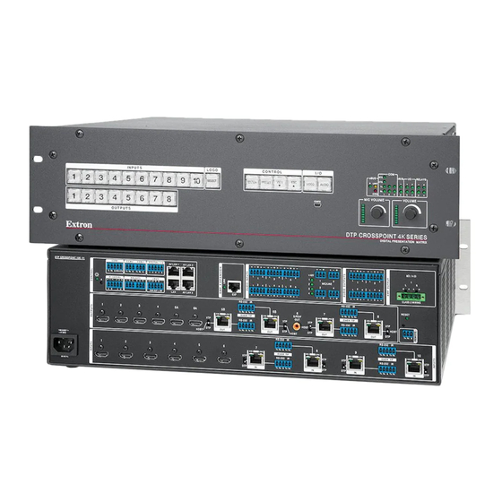
The non-IPCP, SA, and MA models have similar features, with differences in the control connections and Amplified Output block only. Figure 2 shows the rear panel of a composite DTP CrossPoint 108 4K model, featuring elements of different models. Figure 3 shows only the Amplified Output block portion of the MA models. -
Page 19: Video And Twisted Pair Input And Output Connections And Switches
Video and Twisted Pair Input and Output Connections and Switches DTP CROSSPOINT 108 4K COM 1 COM 2 COM 3 DIGITAL I/O LAN 1 +48V Tx Rx RTS CTS Tx Rx G Tx Rx G 1 2 3 4 G... -
Page 20: Audio Input And Output Connections
The video and embedded audio signals output on TP outputs 5b and 6b are NOTE: duplicated on HDMI outputs 5a and 6a. Audio Input and Output Connections DTP CrossPoint IPCP SA DTP CROSSPOINT 108 4K COM 1 COM 2 COM 3 DIGITAL I/O LAN 1... - Page 21 Mic/Line inputs 1 through 4 — Connect microphones or other mono audio inputs to these 3-pole, 3.5 mm captive screw connectors (see Mic/Line input connectors on page 19 to wire the connectors). +48 V (phantom power) LEDs — These LEDs light to indicate that +48 V +48V phantom power is applied to the associated mic/line inputs.
-
Page 22: Serial And Ir Insertion Connections
Serial and IR Insertion Connections DTP CROSSPOINT 108 4K COM 1 COM 2 COM 3 DIGITAL I/O LAN 1 +48V Tx Rx RTS CTS Tx Rx G Tx Rx G 1 2 3 4 G MIC/LINE IR/SERIAL RELAYS eBUS 3 4 C... -
Page 23: Switcher Reset
3.5 mm, 3-pole captive screw connector for remote control of the switcher (see Serial and IR port connectors on page 20 to wire the connector). Switcher Reset Tx Rx G DTP CROSSPOINT 108 4K COM 1 COM 2 COM 3 DIGITAL I/O LAN 1 +48V... -
Page 24: Detailed Pin Assignments, Wiring, And Sample Applications
Detailed Pin Assignments, Wiring, and Sample Applications HDMI connectors Use the LockIt Lacing Brackets, supplied with the switcher, to securely fasten HDMI cables to devices as follows (see figure 10). Figure 10. Installing the LockIt Lacing Bracket Plug the HDMI cable into the panel connection ( Loosen the HDMI connection mounting screw from the panel enough to allow the LockIt lacing bracket to be placed over it ( ). - Page 25 TP connectors All of the RJ-45 ports; the TP input and output ports, the Expansion port, and the LAN (Ethernet) ports on the switcher or IPCP control processor; use twisted pair cables. It is essential that the TP cables be the correct type and that they be properly terminated with the correct pinout.
- Page 26 TP and Expansion ports The TP input and output ports are compatible with Extron XTP DTP 24 SF/UTP cables, as well as CAT 5e, 6, 6a, and 7 shielded twisted pair (F/UTP, SF/UTP, and S/FTP) cable. The Expansion port requires CAT 5e, 6, 6a, or 7 shielded twisted pair cable. For the TP ports only —...
- Page 27 Analog audio input connectors See figure 12 to wire a connector for the appropriate input type. Connectors are included with the switcher, but you must supply the audio cable. Use the supplied tie-wrap to strap the cable to the extended tail of the connector. Ring Sleeve Sleeves...
- Page 28 Analog audio output connectors Connect audio devices, such as an audio amplifier or powered speakers, to these 3.5 millimeter, 5-pole captive screw connectors (see figure 14 to wire an output connector). These connectors output the tied unamplified, line level audio. Use the supplied tie-wrap to strap the audio cable to the extended tail of the connector.
-
Page 29: Front Panel Configuration Port
S/PDIF output connector Figure 16 shows the cable wiring for the S/PDIF jack. This is a 75-ohm cable with a standard RCA connector. Tip (+) Sleeve ( ) RCA Connector Figure 16. Wiring an RCA Connector for the S/PDIF Jack Front Panel Configuration Port CONTROL eBUS... -
Page 30: Operation
Operation This section describes the front panel operation of the DTP CrossPoint 4K Series, including: Front Panel Controls and Indicators • Front Panel Operations • Rear Panel Operations • Troubleshooting • Configuration Worksheets • Front Panel Controls and Indicators The front panel controls (see figure 18) are grouped into four sets. The input and output buttons, , are grouped on the left side of the control panel. -
Page 31: Input And Output Buttons
Input and Output Buttons NOTE: See Front Panel Operations, beginning on page 29 for detailed descriptions of the following operations. Primary functions Action Select input or output for tie being created. Indication Blink: potential tie/untie. Lit: current tie Amber: video and audio tie Green: video only tie Red: audio only tie through... -
Page 32: Logo Button
Front Panel Operations, beginning on page 29 for detailed descriptions of NOTE: See the following operations. Output buttons (see figure 18 on page 22) — The output buttons have one primary function (❏) and four secondary functions (•): ❏ Select and identify an output for ties. Select a preset. -
Page 33: Control Buttons
Control Buttons NOTE: See Front Panel Operations, beginning on page 29 for detailed descriptions of the following operations. Primary functions Action Save changes Select Preset mode Select View mode Cancel or escape Indication Blink: Save needed Recall preset View mode selected Blinks once ENTER PRESET... - Page 34 Front Panel Operations, beginning on page 29 for detailed descriptions of NOTE: See the following operations. View ( ) button (see figure 18 on page 22)— The View ( ) button has one primary < < function (❏) and five secondary functions (•): ❏...
-
Page 35: I/O Buttons
I/O Buttons NOTE: See Front Panel Operations, beginning on page 29 for detailed descriptions of the following operations. Primary functions Action Select video Select audio Indication Green: selected Red: selected VIDEO AUDIO Secondary functions Control insert Indication Blink: Control Insert Configuration Mode. configuration Resets Action:... -
Page 36: Control Processor Indications
Volume Range LEDs Lit Increment (dB) (dB per step of knob rotation) -4 to +12 All 8 LEDs lit. -9 to -5 Bottom 7 LEDs lit. -14 to -10 Bottom 6 LEDs lit -19 to -15 Bottom 5 LEDs lit. -29 to -20 Bottom 4 LEDs lit. -
Page 37: Front Panel Operations
Front Panel Operations The following sections detail the power-up process and then provide sample procedures for the following actions: Creating ties, sets of ties, and configurations (see page 30) • Changing a configuration (see page 32) • Viewing ties, sets of ties, and configurations (see page 34) •... -
Page 38: Making Ties
Making Ties The current configuration can be changed using the front panel buttons. Change the current configuration as follows: Press the button to clear any input button indicators, output button indicators, or control button indicators that may be lit. Press the button and button as necessary to select video, audio, or both Video... - Page 39 Example 1: Create a set of video and audio ties Clear all selections: Press and release the button. Press the Esc button to clear all selections. C O N T R O L VIEW ENTER PRESET The button blinks once. Select video and audio for the tie: Press and release the button and the Video...
- Page 40 Example 2: Add a video tie to a set of video and audio ties In the following example, a new video tie is added to the current configuration. The example shows the front panel indications that result from your actions. NOTE: This example assumes that you have performed example 1 on the previous...
- Page 41 Example 3: Remove a tie from a set of ties In the following example, an existing tie is removed from the current configuration. The example shows the front panel indications that result from your actions. NOTE: This example assumes that you have performed example 1 on page 31 and example 2...
-
Page 42: Viewing The Configuration
Viewing the Configuration The current configuration can be viewed using the front panel buttons. The View-only mode prevents inadvertent changes to the current configuration.. View the current configuration as follows: Press the button to clear any input button indications, output button indications, the Logo button, or control button indications that may be lit. - Page 43 Example 4: Viewing video and audio, audio only, and video only ties The following example shows how to view the video and audio, audio only, and video only ties in the current configuration. The steps show the front panel indications that result from your action.
- Page 44 Deselect video: Press and release the button. Video Press the button. The Audio button I / O remains lit red to The button is unlit or indicate that only background illuminated VIDEO AUDIO audio is selected. when deselected. The output buttons for outputs that are tied to input 5 light red to indicate audio ties (audio breakaway).
-
Page 45: Recalling Presets
Preset Preset Figure 23. DTP CrossPoint 108 4K Preset Locations Example 5: Recalling a preset In the following example, a preset is recalled to become the current configuration. The steps show the front panel indications that result from your action. -
Page 46: Assigning And Unassigning Logos
Recall the preset: Press and release the button. The configuration stored in Enter the selected memory location is now the current configuration and can be viewed in the View-only mode (see example 4 on page 35). Press the button. C O N T R O L VIEW ENTER PRESET... - Page 47 Assign the logo: Press and release one or more of output buttons to assign the logo to those outputs. Outputs 1through 4 are Push the desired output buttons. not selectable. Enter blinks to indicate the ENTER need to confirm the assignment. OUTPUTS The buttons blink to indicate the selection.
-
Page 48: Configuring The Input Audio
Configuring the Input Audio The input audio can be configured to tie the digital audio input (on the HDMI or TP connector), the analog audio input (on the local connector), or to automatically select the input, with digital having priority. Configure the input audio as follows: Press the button to clear any input button indications, output button indications, the Logo button, or control button indications that may be lit. -
Page 49: Configuring The Tp Insertion Ports
Configuring the TP Insertion Ports The control signal insertion ports on TP inputs and outputs can be configured for Ethernet insertion or RS-232 pass-through. Configure the control insertion as follows: Press the button to clear any input button indications, output button indications, the Logo button, or control button indications that may be lit. -
Page 50: Selecting The Remote Port Baud Rate
Selecting the Remote Port Baud Rate The switcher can operate at the 9600, 19200, 38400, and 115200 baud rate. This variable can be viewed and changed from the front panel, as follows: Select Serial Port Configuration mode: Simultaneously press and hold all Control buttons ( , and Enter... -
Page 51: Setting The Front Panel Locks (Executive Modes)
Setting the Front Panel Locks (Executive Modes) The matrix switcher has three levels of front panel security lock that limit the operation of the switcher from the front panel. The three levels are: Lock mode 0 — The front panel is completely unlocked. All front panel functions are •... -
Page 52: Performing A System Reset From The Front Panel
Selecting Lock mode 2 or toggling between mode 2 and mode 1 NOTES: • If the switcher is in Lock mode 0 or mode 1, this procedure selects mode 2. • If the switcher is in Lock mode 2, this procedure selects mode 1. Toggle the lock on and off by pressing and holding the button and the button... -
Page 53: Rear Panel Operations
Rear Panel Operations The rear panel has a Reset button that initiates three levels of resets (numbered 1, 4, and 5 for the sake of comparison with Extron IPL products). The Reset button is recessed, so use a small screwdriver, a pointed stylus, or a ballpoint pen. NOTE: This section describes the functions of the switcher Reset button (see page 45), not the IPCP control module Reset button. -
Page 54: Performing A Mode 1 Reset
Performing a Mode 1 Reset The hard reset function restores the switcher to the base firmware that it was shipped with. After a hard reset, events do not automatically start, but user settings and files are retained. Perform a hard reset as follows: NOTE: The hard reset restores the factory-installed firmware. -
Page 55: Performing Mode 4 And Mode 5 Resets
Performing Mode 4 and Mode 5 Resets Perform a soft reset of the switcher as follows: Use a small screwdriver to press and hold the switcher (not IPCP) button on the Reset right side of the rear panel until the Reset LED and the front panel Video Audio buttons blink the number of times for the desired reset: twice (IP settings reset) or three... -
Page 56: Coniguration Worksheets
Configuration Worksheets Rather than trying to remember the configuration for each preset, use worksheets to record this information. Make copies of the blank worksheet (see Configuration Worksheet page 50) and use one for each preset configuration. Cross out all unused or inactive inputs and outputs. -
Page 57: Worksheet Example 2: Daily Configuration
Worksheet Example 2: Daily Configuration Figure 31 continues from worksheet example 1 by showing the video and audio ties in the preset 1 configuration. Black lines shows video ties, red lines show the audio ties. Input sources Camera/ Camera PC 1 PC 2 VTG 400/ DTP T... -
Page 58: Configuration Worksheet
Configuration Worksheet Input sources Output destinations Preset # Title: Video: Audio: Fill in the preset number and use colors, or dashes, etc. to make connecting lines. Indicate if the configuration is for video, audio, or both. Input sources Output destinations Preset # Title: Video:... -
Page 59: Programming Guide
Programming Guide The switcher can be remotely controlled, monitored, or configured with the following: The Extron Product Configuration Software and DSP Configurator software (see Matrix • Software on page 73) HTML Operation Built-in HTML pages (see on page 141) • SIS commands (see below) •... -
Page 60: Usb Port
USB Port The front panel Configuration port (see item on page 21) is a standard USB port. A USB cable, terminated on one end with a USB mini-B male connector, is available at any local electronics store. Ethernet (LAN) Ports The Ethernet cable can be terminated as a straight-through cable or a crossover cable and must be properly terminated for your application (see item... - Page 61 Establishing a connection Establish a network connection to a DTP CrossPoint switcher as follows: Open a TCP socket to port 23 using the IP address of the switcher. NOTE: If the local system administrators have not changed the value, the factory-specified default, 192.168.254.254, is the correct value for this field.
-
Page 62: Host-To-Switcher Instructions
(underlined). The switcher does not expect a response from the host, but, for example, the host program might request a new status. (c) Copyright 20yy, Extron Electronics DTPCP108, Vx.xx, 60-nnnn-nn {day, date, time} The switcher initiates the message on the Remote RS-232 port when it is first Copyright powered up and on a newly connected Internet protocol (IP) port. -
Page 63: Switcher Error Responses
Switcher Error Responses When the switcher receives an SIS command and determines that it is valid, it performs the command and sends a response to the host device. If the switcher is unable to perform the command because the command is invalid or contains invalid parameters, the switcher returns an error response to the host. -
Page 64: General Matrix Switcher Commands
General Matrix Switcher Commands Symbol definitions = Carriage return and line feed = Carriage return (no line feed) = Pipe (can be used interchangeably with the character) • = Space = Escape key = Can be used interchangeably with the character = Input number –... - Page 65 = Name 12 characters maximum upper- and lower-case alphanumeric characters and _ / and spaces are valid. NOTE: The HTML language reserves certain characters for specific functions (see Special Characters on page 72). = Scaler preset – = Preset number –...
-
Page 66: Command And Response Table For Matrix Switcher Commands
Command and Response Table for Matrix Switcher Commands SIS Command Response Additional description Command Function (Host to Unit) (Unit to Host) Create Ties NOTES: • Commands can be entered back-to-back in a string, with no spaces. For example: 1*1!02*03%02*03$4*4!. • The quick multiple tie and tie input to all output commands activate all I/O switches simultaneously. - Page 67 EDID Values Table Source or value Source or value Source or value Source or value Assigned output values Output 1 Output 4 Output 6a Output 8 Output 2 Output 5a Output 6b Output 3 Output 5b Output 7 DVI – PC values 1024x768 @ 50 Hz 1280x1024 @ 50 Hz 1440x900 @ 50 Hz...
- Page 68 Command and Response Table for Matrix Switcher Commands (continued) SIS Command Response Additional description Command Function (Host to Unit) (Unit to Host) Video mutes Mute video only Mute output video (video off, sync on). Mute video and sync Mute output video and sync.
- Page 69 Command and Response Table for Matrix Switcher Commands (continued) SIS Command Response Additional description Command Function (Host to Unit) (Unit to Host) HDCP notification Set green screen *1HDCP HdcpN Set black screen *0HDCP HdcpN View HDCP notiication X1@] HDCP HDCP status View input HDCP status for verbose mode 2 and 3.
- Page 70 Command and Response Table for Matrix Switcher Commands (continued) SIS Command Response Additional description Command Function (Host to Unit) (Unit to Host) Input sync detection View all input connections Frq00• Each is the connection status of an input, starting from input 1. NOTE: The “...
- Page 71 Command and Response Table for Matrix Switcher Commands (continued) Command Function SIS Command Response Additional description (Host to Unit) (Unit to Host) Resets Reset all global presets Clear all presets and names. Reset one global preset Clear preset and name. EX2$ X2$] System reset (factory default)
- Page 72 Command and Response Table for Matrix Switcher Commands (continued) SIS Command Response Additional description Command Function (Host to Unit) (Unit to Host) View and erase file directory NOTE: The response to the View File Directory command differs, depending on whether the command is sent via an RS-232 or Telnet connection or sent via a Web browser connection.
- Page 73 Command and Response Table for Matrix Switcher Commands (continued) SIS Command Response Additional description Command Function (Host to Unit) (Unit to Host) Vertical shift Specify a value Set the vertical location of irst active line EX2! X3!] VCTR Vctr in output Increment value Increment the value by one line (shift up).
- Page 74 Command and Response Table for Matrix Switcher Commands (continued) SIS Command Response Additional description Command Function (Host to Unit) (Unit to Host) Overscan NOTE: The Overscan command applies to SMPTE input rates only (NTSC or PAL, 480p to 1080p, 50 Hz or 60 Hz). Set overscan value X3$] OSCN...
- Page 75 Command and Response Table for Matrix Switcher Commands (continued) SIS Command Response Additional description Command Function (Host to Unit) (Unit to Host) Scaler output rate Set scaler output rate Set the scaler to output on output EX2! X3(] RATE Rate Set the scaler to output 720p video at Example: 3*34RATE...
- Page 76 Command and Response Table for Matrix Switcher Commands (continued) SIS Command Response Additional description Command Function (Host to Unit) (Unit to Host) Logo Commands Logo on and off Assign a logo to an output Assign logo to output LOGO LogoE X4!] Assign logo 4 to output 6.
- Page 77 Command and Response Table for Matrix Switcher Commands (continued) SIS Command Response Additional description Command Function (Host to Unit) (Unit to Host) RS-232 Insertion Commands (continued) Ethernet and serial port insert parameters Set serial port parameters EX4# X4& •Ccp X4&] Read serial port parameters EX4# X4&]...
-
Page 78: Port Specific And Communications Protocol Sis Commands
Port Specific and Communications Protocol SIS Commands Symbol definitions = Password Up to 128 characters, all characters valid with the exception of pipe (|) NOTE: The HTML language reserves certain characters for specific functions (see Special Characters on page 72). = A 2- to 6-digit time zone code, such as “... -
Page 79: Command And Response Table For Remote And Communications Protocol Commands
View Web port map <port #> IPCP Pro 350 Information The DTP CrossPoint 108 4K IPCP models include a built-in IPCP Pro 350 control processor that supports the LAN ports and other functionality. See the IPCP Pro Series User Guide at www.extron.com. -
Page 80: Special Characters
Special Characters The HTML language reserves certain characters for specific functions. The switcher does not accept these characters as part of names, passwords, or locally created file names. The switcher rejects the following characters: {space (spaces are valid for use in names)} + ~ , @ = ‘ [ ] { } < > ’ “ semicolon (;) colon (:) | \ and ?. -
Page 81: Matrix Software
Matrix Software The DTP CrossPoint Matrix Switcher can be remotely controlled, monitored, or configured via: Programming Guide SIS commands (see on page 51) • HTML Operation Built-in HTML pages (see on page 141) • • The following two Extron computer programs: Product Configuration Software •... -
Page 82: Software Operational Considerations And Installation
Software Operational Considerations and Installation Software Operation via Ethernet item When the switcher is connected to an Ethernet WAN or LAN (see [non-IPCP item model] on page 14 or [IPCP models] on page 15), up to 200 users can be connected to locally or remotely operate it, using the DSP Configurator or Product Configuration Software. - Page 83 Click the Software or Firmware link as appropriate to the operation you are figure performing (see on the previous page). Many popular software packages have direct links on the Download page that TIP: you can click instead. Figure 33 shows the PCS link. Click Download for the desired software or firmware to download ( Jump to the nearest page of downloads by clicking the desired iltering letter.
-
Page 84: Product Coniguration Software
PC desktop: NOTE: C:\Program Files(x86)\... for 64-bit Windows OS. Product Configuration Software — Folder — C:\Program Files\Extron\Extron PCS • Group folder — Extron Electronics\Extron Product Configuration • Software • Check for Extron PCS Updates •... -
Page 85: Device Menu
Connect the PC to switcher via the front panel Configuration port. figure 36 Select (click) your DTP CrossPoint (see on the previous page, ) and click ). PCS opens to the EDID Minder panel (see figure 37 below). Connect The PCS provides a way to assign and unassign a logo to one or more scaled outputs Assigning and Unassigning Logos (outputs 5 through 8) (see on the next page). -
Page 86: Assigning And Unassigning Logos
Settings — Displays a wide assortment of hardware and communication settings. • Select settings can be changed: Device name • Date and time • Administrator and user passwords • NOTE: An administrator password must be assigned before a user password. RS-232 baud rate for the rear panel Remote port •... -
Page 87: Updating The Firmware
figure 38 If necessary, click the tab to open the logos controls (see on the Logos previous page, Click the desired logo in the Logo Management column ( Click the desired Logo Assigned to: output check box to toggle the logo assigned and unassigned. - Page 88 1 1 1 1 1 1 1 1 1 1 1 1 1 1 1 1 2 2 2 2 2 2 2 2 Folder Where Firmware is Saved. 3 3 3 3 3 3 3 3 Figure 39. Extracting Firmware Upgrade Files >...
- Page 89 1 1 1 1 1 1 1 1 2 2 2 2 2 2 2 2 3 3 3 3 3 3 3 3 4 4 4 4 4 4 4 4 6 6 6 6 6 6 6 6 Figure 40.
-
Page 90: Dsp Conigurator Program
Configurator program. Start the DSP Configurator Program by clicking the desktop icon or as follows: Click Start > All Programs > Extron Electronics > DSP Configurator > DSP . The DSP Configurator startup screen displays (see figure 41). Configurator Figure 41. - Page 91 * This output 1 amplifier block (in ) is not present on non-IPCP models. Figure 42. DSP Configurator (Stereo Audio) Program Window DTP CrossPoint 4K Series Matrix Switchers • Matrix Software...
-
Page 92: Using The Program
Using the Program In the DSP Configurator window in Emulate mode, you can tailor a variety of audio parameters and then transfer them to the DTP CrossPoint by going to Live mode (connected to a DTP CrossPoint). You can also switch to Live mode and then tailor the Emulate audio settings in real time, while listening to the audio output with a critical ear (see mode vs. - Page 93 Audio signal processor chains and control blocks Each of the six signal processing chains ( , and ) consists of one or more control blocks of two basic types that are specific to that chain: gain, trim, post-gain, and volume control blocks (collectively known as “gain blocks” – , see figure 43 ) and processor blocks ( , see figure 44 ).
- Page 94 possible processes (such as filters) that can be inserted into the audio stream. For blocks that provide more than one processor, only one processor can be selected. Each block can be inserted by a double-click or right-click > and selecting the desired processor Insert figure 44 (see...
- Page 95 figure 42 Line audio input signal controls (see on page 83, The program audio input signal processor chain makes adjustments to program audio material before it is tied to specific outputs. Gain control block — The always-present gain control provides left and right channel controls to adjust the audio level of each input 3 3 3 3 3 3 3 3...
- Page 96 Multi-Channel — The detected format is any compressed or encoded digital • audio format, such as Dolby or DTS multi-channel. Multi-channel input audio does not pass through the DSP regardless of • selected ). Gain, mute controls, and meters are disabled and Audio Format unavailable for operation throughout the DSP.
- Page 97 Filter block — The filter processor block, when first inserted, provides one of ten filter selections; additional filters can then be added. A filter attenuates (removes) or boosts a range of frequencies from an audio waveform, while passing other frequencies. Click the desired filter to select NOTE: Selecting inserts two separate filters.
- Page 98 Dynamics blocks (2) — The two dynamics processor blocks, when inserted, 1 1 1 1 1 1 1 1 2 2 2 2 2 2 2 2 each provide one of four dynamic processors. A dynamic processor alters 3 3 3 3 3 3 3 3 the dynamic range of an audio signal, the difference between the loudest to 4 4 4 4...
- Page 99 Trim control — The always-present trim control provides separate left and right input channel faders for fine adjustment with a gain range of -12 dB to +12 dB in 0.1 dB increments. The default setting is unity gain (0.0 dB). Click and drag the desired fader ( ) or click in the dB field ( ) and enter a...
- Page 100 AEC block — The AEC block, when inserted, contains a number of meters and indicator LEDs necessary for gain structure setup and monitoring activity. 1 1 1 1 1 1 1 1 AEC Tutorial on page 129 for a more detailed examination of the Acoustic Echo Cancellation functions.
- Page 101 Ducking block — The ducking processor block, when inserted, provides a means to duck, or lower the level of 1 1 1 1 1 1 1 1 5 5 5 5 5 5 5 5 one or more input signals (ducking targets, such as 2 2 2 2 2 2 2 2 microphones, the program material, or audio input on the...
- Page 102 by (dB): — Individual attenuation settings for each duck target in dB. The default is 20.0 dB. If additional attenuation of a target is required, increase this value. The current source setting is not available. The attenuation range is 80.0 to 0.0 dB in 0.1 dB increments. Priority —...
- Page 103 AM block — The automixer block, when inserted, manages multiple microphone sources, gating or varying input gain automatically to improve the performance when 1 1 1 1 1 1 1 1 2 2 2 2 2 2 2 2 multiple mics are in use. Automix Tutorial on page 132 for a more detailed examination of the automixing functions and details of the...
- Page 104 Gain control — The always-present gain control provides a single fader with a gain range of 12 dB to -100 dB, adjustable in 0.1 dB increments, with a level setting readout below the fader. 1 1 1 1 1 1 1 1 Click and drag the fader ( ) or click in the dB field ( ) and enter a value.
- Page 105 Filter block — The filter processor block, when first inserted, provides one of four filter selections; additional filters can be then be added. The available filters and the process for adding additional filters are as Filter block described for the Line audio on page 89.
- Page 106 Gain (pre-mixer) control block — The always-present gain control provides left and right channel controls to adjust the audio level of each audio output from the AV switcher block through a range of -100 dB to +12 1 1 1 1 1 1 1 1 1 1 1 1 1 1 1 1...
- Page 107 figure 42 Switcher-to-output mixer block (see on page 83, The switcher-to-output mixer block (see figure 46) sends audio from the AV matrix block to the output. It is an array of points where the output of the AV matrix can be mixed into the output of the DSP.
- Page 108 Simplified mixer signal flow = Unmute = Mute Figure 47. Simplified Mixer Signal Flow • Mix-point mutes (indicated by in figure 47, a graphic representation of the mixer) do not block the horizontal signal flow. Unless muted before the mixer, audio always flows from left to right through the mixer.
- Page 109 figure 42 Mic-to-output mixer block (see on page 83, Virtual returns-to-output mixer block ( Expansion inputs-to-output mixer block ( These three mixer blocks (see figure 48) are an array of points where mic, virtual bus, and expansion bus audio can be further mixed into the left and right channels of audio outputs 1 through 8.
- Page 110 figure 48 To mute or unmute an input, right-click a mix-point (see on the previous page, You can also double-click one of the mix-points to open a mixing dialog box and then click button ( ) in the dialog box. Mute The dialog boxes feature a fader control that provides a mix (level) adjustment with a gain range of -100 to +12 dB in 0.1 dB increments.
- Page 111 Filter block — The filter processor block, when first inserted, provides one of ten filter selections; additional filters can be then be added. The available filters and adding additional filters are as described for the Line Filter block audio on page 89. NOTE: Selecting inserts two separate filters.
- Page 112 NOTE: For digital volume controls only, the selection ( Output Signal Source below) affects the remaining controls in the block. If is selected, Original No Audio all other controls in the block become unavailable for selection. Click and drag the desired fader ( ) or click in the dB field ( ) and enter a value.
- Page 113 Switcher-to-virtual-send-bus 1 1 1 1 1 1 1 1 Mixer 3 3 3 3 3 3 3 3 3 3 3 3 3 3 3 3 Mic-to-virtual-send-bus 4 4 4 4 4 4 4 4 Mixer 2 2 2 2 2 2 2 2 4 4 4 4 4 4 4 4...
- Page 114 Group masters Any of the gain, volume, trim, bass, loudness, and treble fader controls for one or more gain blocks can be grouped with other gain blocks of the same type (in the same location in the audio signal path but for different inputs or outputs). This creates single-fader control of the entire group (see figure 51).
- Page 115 Each individual volume control in the group can be set for that output, but when you move the group fader, the faders for all three outputs move in tandem, retaining their relative levels. figure 51 NOTE: By default, group 1 ( , in on the previous page) is configured as the Gain (Pre-mixer) control block...
- Page 116 In the field, click the to expand the tree and then Select Control Type Gain Mute figure select a control to assign it to the group (see on the previous page). In the field, click the desired check boxes to select or Available Group Members deselect those blocks as members of the group ( NOTE:...
- Page 117 Viewing and using a group master Click to open the dialog box (see figure 54). View > Group Controls Group Controls Figure 54. Group Controls Dialog Box • Slide a group fader up and down to adjust all gain controls in the group. Click and drag a soft limit ( ) to set the upper or lower volume limits for the group.
- Page 118 Click in the dialog box menu bar • Tools > Group Details Report Group Controls figure 54 (see on the previous page) to create a text file that details all created groups (see figure 56). GROUP DETAILS REPORT Group #1 (Program Volume) Processor Type: Pre-mixer Gain Current Gain value: 0 dB Current Group Members:...
-
Page 119: Presets
The audio-only I/O page, selected by clicking in the legend field, clicking Audio Only , or pressing the keyboard <F3> key. The appearance is identical to View > Audio I/O figure 42 the video & audio I/O page (see on page 83), and the same audio controls are AV matrix block ( available. - Page 120 Mark the desired gain and/or processor blocks: Click a processor block. The block is marked by a green outline ( ). The processor block and all of its settings is selected to be saved as a preset. Ctrl-click additional processor blocks as desired. To mark multiple successive processor blocks in a TIP: chain, use right-click >...
-
Page 121: Emulate Mode Vs. Live Mode
Emulate mode vs. Live mode The DSP Configurator program always starts in Emulate mode. In Emulate mode, you can perform all of the functions available in the DSP Configurator program, without connecting a switcher to the computer, and save all of the ties and settings to a configuration file on your PC. - Page 122 If you selected TCP/IP in step 2: Observe the field in the window. The field displays the IP Connection IP Address last IP address entered. If the IP Address field is correct, proceed to step 3b. If the address is not correct, either click in the field and enter the IP Address figure 59...
- Page 123 If necessary and as desired, click either the: radio button (see figure, ) (to configure the DSP Configurator program to • Pull step 7 match the switcher — proceed to on the next page) radio button ( ) (to configure the switcher to match the DSP Configurator •...
-
Page 124: Dsp Configurator Windows Menus
If you want to tailor the push to the switcher (push just the configuration, just the presets, or the configuration and selected presets), click the button (see Advanced figure 60 on the previous page, ) and proceed to step 6a. To push all of the DSP Configurator ties, gain and processor blocks, and presets to the switcher, proceed to step 7. - Page 125 DSP Configurator Edit menu Cut — Copies all of the parameters of a selected processor block or set of selected blocks to the clipboard and removes the blocks from the processor stream. NOTES: • Gain blocks are always present and cannot be •...
- Page 126 DSP Configurator Tools menu Presets — Allows you to mark all items, save a preset, and clear marked items: Mark All Ties — Mark (select) all created ties to save as a • preset. Mark All Items — Mark (select) all parts of the current •...
- Page 127 DSP Configurator Window menu Cascade — Rearranges all open DSP Configurator program windows, including dialog boxes, in a cascading array. — Closes all open dialog boxes. Close All Windows Individual windows — Brings the associated dialog box to the front of the desktop.
-
Page 128: Keyboard Navigation
Keyboard Navigation The DSP Configurator program is fully navigable using the computer keyboard. Some keyboard navigation behavior matches Windows standards, while other behaviors are specific to the DSP Configurator program. When the program is started, the cursor focus is in the upper left corner of the program audio input (line signal processor chain [see figure 62, ]). - Page 129 Arrow ( , , and ) keys — • Navigate up, down, left, and right within any of the areas in the DSP Configurator. figure 62 Jump from the audio input blocks (see on the previous page, ) into the input name fields ( Jump from the output blocks ( ) into the output name fields (...
- Page 130 Highlighting and marking items, cutting or copying, saving a preset When an item within the program is selected, it is green highlighted. One or more highlighted items can be cut, copied, pasted, or saved as a preset. The cut, copy, and <Alt>...
- Page 131 1 1 1 1 1 1 1 1 1 1 1 1 1 1 Enter 2 2 2 2 2 2 2 2 2 2 2 2 2 2 3 3 3 3 3 3 3 3 3 3 3 3 3 3 4 4 4 4 4 4 4 4 4 4 4 4 4 4...
-
Page 132: Signal Path Building Blocks
Signal Path Building Blocks All of the inputs and outputs that have name blocks ( in figure 64 ) are discrete signal paths: Visible in figure 64 Not visible in figure 64 Audio & Video (line) in Virtual returns in •... - Page 133 Selecting a building block Select a hand-held microphone configuration as follows: Open the Building Blocks dialog box: Click the Mic Input 1 number box. The dialog box opens ( Building Blocks A Building Block dialog box opens. Click the number. 1 1 1 1 1 1 1 1 The modules in the box are dependent on the device type clicked.
- Page 134 Adding a building block Custom building blocks can be created if necessary, such as when a new mic is connected to an input. The signal path can be configured for that specific mic and then saved as a new building block as follows: Modify the processing chain for an input or output.
- Page 135 NOTE: You can choose to overwrite an existing building block: Enter an existing name for the new coniguration. The program prompts to warn that an existing coniguration will be overwritten. 1 1 1 1 1 1 1 1 Click Click Click the Add button.
- Page 136 Organizing listed building blocks Building blocks can be organized within default folders or within new folders. You can move individual building blocks or a folder with all of its contents to a new location. Create a new folder in the dialog box by clicking the Organize Building Blocks icon (...
-
Page 137: Aec Tutorial
AEC Tutorial The DTP CrossPoint 4K Series provide an acoustic echo cancellation processor for each of the four mic/line inputs. A single reference can be selected for each AEC from a list of the other three mic/line inputs or the virtual returns. About AEC Echo occurs when audio from a talker in the far end is received and amplified into the room of the near end listener. -
Page 138: Advanced Aec Controls
Advanced AEC Controls Click on the open/collapse icon ( ) at the bottom of the AEC dialog to reveal the advanced AEC controls. Advanced control functionality consists of: Non-linear processing (NLP) controls • Additional controls • NLP controls Enable NLP — This box is selected by default. NLP is necessary 1 1 1 1 1 1 1 1 for the removal of echo. -
Page 139: Ducker Priority Tutorial
Ducker Priority Tutorial Insert a ducker using one of the Double-click the block, Right-click the box to open context -or- then click Ducker menu, then click Insert Ducker methods at right. Once inserted, double-click on the ducker block to open the Ducker dialog box. -
Page 140: Automix Tutorial
figure 67 As was shown in on the previous page, mic 1 is the first source. Since it was selected as a ducking target, mic 1 is not available as a target of mic 2. Open the dialog box for the input and select the desired duck targets. In this Ducking example mics 3 and 4 are the ducking targets of mic 2. - Page 141 Configure an Automix Group: A channel must first have an active automix block before it can be included in an automix group. Insert an AM processing block in the desired channel. Double-click the inserted to open it. AM block Select the group number from a range of 1 through 8. Set the parameters for the channel.
-
Page 142: Expansion Port Operation Within The Dsp
Expansion Port Operation within the DSP DMP Expansion Port and LED, in the Installation section The expansion port (see on page 13) allows a DTP CrossPoint matrix switcher and an Extron DMP 128 ProDSP Digital Matrix Processor to be connected together for bidirectional communications with 16 channels of input and output audio. - Page 143 Expansion input channels The DTP CrossPoint accepts 16 expansion input channels (see figure 70). Expansion inputs 9 through 16 are via Virtual Returns 9 through 16 in the DMP 128. DTP CrossPoint 108 DMP 128 ProDSP Digital Matrix Processor Figure 70. Expansion Input Channels Connection No special setup is required;...
-
Page 144: Optimizing The Audio
Optimizing the Audio Program material that you are familiar with is preferable for the following procedures, otherwise, pink noise can be used. The Extron VTG 300 or VTG 400 is recommended to provide the pink noise. TIP: Input Clipping and Clipping Meters Audio clipping is a form of distortion that occurs when the signal peaks (or excursions) exceed the limits of the circuit, cutting off the excursions of a signal. -
Page 145: Adjusting The Pre-Matrix Trim
Adjusting the Pre-matrix Trim The pre-matrix trim control can be used to compensate for any level changes caused by signal processing before the trim control. Adding a compressor generally reduces the signal level, while a filter can either boost or cut the overall signal level. NOTE: This procedure is valid only if no processing is active in the output signal path, and if post-matrix trim value is set to 0 dB (unity gain). -
Page 146: Setting The Mic Input And Mic Mix-Point Levels
Setting the Mic Input and Mic Mix-point Levels Double-click the mic mix-point to be set, opening the dialog box for that mix-point. Unmute the mix-point (mixing in the mic signal). The default level is 0.0 dB, or unity gain. Connect your chosen microphone to mixed mic/line input. Open the mic input gain dialog box for the mixed mic. -
Page 147: Calibrating Loudness
Calibrating Loudness The basic gain structure is now set up. From this point, loudness can be calibrated using an SPL meter, a critical ear, or a combination of the two. Setting loudness using a meter To calibrate loudness, use a sound pressure level meter set to “C” weighting. Open the post-matrix loudness processor dialog box. - Page 148 To experiment with less loudness compensation, move the Loudness Compensation fader to the left, toward Less For more loudness compensation, move the fader to the right, toward More Any adjustment you make to the Loudness Compensation fader carries through to all listening levels.
-
Page 149: Html Operation
HTML Operation The DTP CrossPoint 4K Series can be remotely controlled via: Programming Guide, beginning on page 51) SIS commands (see • Matrix The Extron Product Configuration Software and DSP Configurator software (see • Software on page 73). The built-in HMTL page (see below) •... -
Page 150: Download The Startup Page And View Switcher Status
Download the Startup Page and View Switcher Status Access the switcher using HTML pages as follows: Start the Web browser program. Click in the field of the browser and highlight any existing text. Address Enter the IP address of the switcher in the field of the browser. - Page 151 Figure 72. Built-in HTML Page (Google Chrome Browser) DTP CrossPoint 4K Series Matrix Switchers • HTML Operation...
-
Page 152: Change The Communications Settings
The input status panel displays the connection status of each input. The output status panel displays the selected resolution of scaler outputs 5a through 8. The various lock icons have the following meanings: Input Status locked ( ) — The input is HDCP compliant. Input Status unlocked ( ) —... -
Page 153: Use Dhcp Check Box
Valid addresses consist of four 1-, 2-, or 3-digit numeric subfields, properly called octets, separated by dots (periods). Each field can be numbered from 000 through 255. Leading zeroes, up to 3 digits total per octet, are optional. Values of 256 and above are invalid. - Page 154 1 1 1 1 1 1 1 1 1 1 1 1 1 1 1 1 2 2 2 2 2 2 2 2 Figure 75. Updating Firmware Navigate to the folder where you saved the firmware upgrade file. Select the file and click (see figure 75, ).
-
Page 155: Set Passwords
Set Passwords Click in the panel (see figure 76, ) to open the dialog box. Passwords Passwords 2 2 2 2 2 2 2 2 3 3 3 3 3 3 3 3 1 1 1 1 1 1 1 1 2 2 2 2 2 2 2 2 3 3 3 3... -
Page 156: Set The Clock
Set the Clock Sync to PC The simplest way to set the switcher clock is to click in the Date/Time Sync to PC panel (see figure 77). The switcher uploads the time and date information from Settings the connected computer. Figure 77. -
Page 157: Dsp Sis Commands
DSP SIS Commands Command and Response Table for DSP SIS Commands Many DSP functions; such as gain (which includes the mix-points), trim, mutes, and some group master functions; can be controlled using SIS commands. These commands follow the same general rules as basic SIS commands, but the variables ( X/ s) tend to be more complex. - Page 158 Line Input Gain Blocks (see figure 42 on page 83, Input Gain Trim Input Gain Trim Input 1 Input 6 Left Left 30000 30100 30010 30110 Right Right 30001 30101 30011 30111 Input 2 Input 7 Left Left 30002 30102 30012 30112 Right...
- Page 159 Post-matrix Gain Blocks (see figure 42 on page 83, Output Gain Output Gain Output Gain Output Gain Output 1 Output 3 Output 5 Output 7 Left Left Left Left 50000 50004 50008 50012 Right Right Right Right 50001 50005 50009 50013 Output 2 Output 4...
- Page 160 Switcher-to-output mixer block (see figure 42 on page 83, Out 1 Out 2 Out 3 Out 4 Out 5 Out 6 Out 7 Out 8 Mixer blocks, part 1 Left Right Left Right Left Right Left Right Left Right Left Right Left Right...
- Page 161 Mic-to-output mixer block (see figure 42 on page 83, Out 1 Out 2 Out 3 Out 4 Out 5 Out 6 Out 7 Out 8 Mixer blocks, part 2 Left Right Left Right Left Right Left Right Left Right Left Right Left Right...
- Page 162 Switcher-to-virtual-send-bus mixer block (see on page 83, figure 42 Mixer blocks, V. Send A V. Send B V. Send C V. Send D V. Send E V. Send F V. Send G V. Send H part 3 Output 1 Left 20016 20017 20018...
- Page 163 Mic-to-virtual-send-bus block (see on page 81, figure 42 Mixer V. Send A V. Send B V. Send C V. Send D V. Send E V. Send F V. Send G V. Send H blocks, Mic in 1 21616 21617 21618 21619 21620 21621...
- Page 164 Line Output Gain Blocks (see figure 42 on page 83, ◊ * This output 1 amplifier block is not present on non-IPCP models. ◊ This is a summing trimmer on the MA (mono audio) model. Output Trim Amp Output Analog Volume HDMI Volume DTP Volume Output 1 power amplifier *...
-
Page 165: Dsp Sis Commands
DSP SIS Commands Command Function SIS Command Response Additional description (Host to Unit) (Unit to Host) Audio trim, gain, and mixing NOTES: • The command format is the same, regardless of the control or mix-point that is to be set; the acceptable adjustment range varies depending on the control or mix-point: •... - Page 166 SIS Command Response Additional description Command Function (Host to Unit) (Unit to Host) Group masters NOTES: • on page 106, for more information about audio group masters. Group masters • A group must have assigned members for these commands to have an effect. •...
-
Page 167: Reference Information
Reference Information This section covers the following DTP CrossPoint 4K Series matrix switcher procedures: • Mounting the Switcher Removing and Installing Button Labels • ATTENTION: • Installation and service must be performed by authorized personnel only. L’installation et l’entretien doivent être effectués par le personnel autorisé •... -
Page 168: Mounting Instructions
Mounting Instructions If desired, rack mount the switcher as follows: Insert the unit into the rack, aligning the mounting bracket holes with those in the rack (see figure 79). Figure 79. Installing the Switcher in a Rack Secure the switcher to the rack using the supplied bolts. Removing and Installing Button Labels Making labels Using the Button Label Generator Program The Button Label Generator software creates labels that you can place in the translucent... - Page 169 Start the Button Label Generator program by clicking the desktop icon or as follows: Click > > > Start All Programs Extron Electronics Button Label Generator > . The Button Label Generator window opens (see Button Label Generator figure 81). Figure 81.
-
Page 170: Making Labels From Paper Templates
Making Labels from Paper Templates The next page provides strips of blank button labels (see on the next Button Label Blanks page). If desired, copy them or cut them out, write button information in each button area as desired, and put them in the windows of the input or output buttons. Installing Labels in the Buttons Install new labels in the front panel buttons as follows: Remove the button from the matrix switcher;... -
Page 171: Button Label Blanks
Button Label Blanks DTP CrossPoint 4K Series Matrix Switchers • Reference Information... - Page 172 Extron Electronics makes no further warranties either expressed or implied with respect to the product and its quality, performance, merchantability, or itness for any particular use. In no event will Extron Electronics be liable for direct, indirect, or consequential damages resulting from any defect in this product even if Extron Electronics has been advised of such damage.
Need help?
Do you have a question about the DTP CrossPoint 108 4K and is the answer not in the manual?
Questions and answers