Extron electronics DXP HD 4K Series Setup Manual
Hdmi matrix switchers
Hide thumbs
Also See for DXP HD 4K Series:
- User manual (116 pages) ,
- Setup manual (4 pages) ,
- User manual (47 pages)
Table of Contents
Advertisement
Quick Links
Download this manual
See also:
User Manual
Advertisement
Table of Contents

Related Manuals for Extron electronics DXP HD 4K Series


Summary of Contents for Extron electronics DXP HD 4K Series
- Page 1 Setup Guide Matrix Switchers DXP HD 4K Series HDMI Matrix Switchers 68-2759-50 Rev. B 01 16...
-
Page 2: Safety Instructions
Safety Instructions Safety Instructions • English Инструкция по технике безопасности • Русский WARNING: This symbol, , when used on the product, is intended to alert the user of the presence of uninsulated dangerous voltage ПРЕДУПРЕЖДЕНИЕ: Данный символ, , если указан within the product’s enclosure that may present a risk of electric на... - Page 3 Trademarks All trademarks mentioned in this guide are the properties of their respective owners. The following registered trademarks, registered service marks, and trademarks are the property of RGB Systems, Inc. or Extron Electronics: Registered Trademarks (®) AVTrac, Cable Cubby, CrossPoint, DTP, eBUS, EDID Manager, EDID Minder, Extron, Flat Field, FlexOS, Global Configurator, GlobalViewer, Hideaway, Inline, IP Intercom,...
- Page 4 Conventions Used in this Guide Notifications CAUTION: Risk of minor personal injury. ATTENTION : Risque de blessure mineure. ATTENTION: • Risk of property damage. • Risque de dommages matériels. NOTE: A note draws attention to important information. Software Commands Commands are written in the fonts shown here: ^AR Merge Scene,,Op1 scene 1,1 ^B 51 ^W^C [01] R 0004 00300 00400 00800 00600 [02] 35 [17] [03] E X! *X1&* X2)* X2#* X2!
-
Page 5: Table Of Contents
Starting the Configuration Selecting Front Panel Lock Program ........47 Mode 2 or Toggling between For More Information ....49 Lock Modes 2 and 1 ....24 Accessing the Web Page .... 50 DXP HD 4K Series • Contents v... - Page 6 DXP HD 4K Series • Contents...
-
Page 7: Introduction
DXP HD 4K models. About the DXP HD 4K Series Matrix Switchers The Extron DXP HD 4K series are digital matrix switchers that route HDMI signals from multiple sources to any or all of up to 16 HDMI-equipped display devices. -
Page 8: Application Diagrams
The DXP HD 4K series switchers all provide easy integration in applications that require reliable HDMI signal routing. They include several convenience features common to Extron matrix switchers such as SpeedSwitch, EDID Minder, Key Minder, global presets, and Ethernet control. In addition, digital audio can be de-embedded from any input and assigned to digital or analog stereo outputs. - Page 9 Room 1 Room 3 Room 2 TouchLink Pro TouchLink Pro TouchLink Pro Figure 2. DXP HD 4K Application for Three Rooms DXP HD 4K Series • Introduction...
- Page 10 DXP HD 4K Series • Introduction...
-
Page 11: Setup
PCS configuration software. See EDID (Extended Display Identification Data) on page 31, or see the configuration program help file and the DXP HD 4K Series User Guide for details. Creating a Tie Create ties and presets as desired (see... -
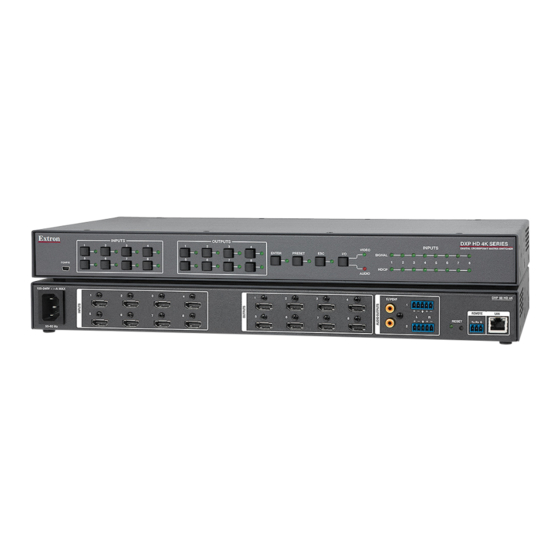
Page 12: Rear Panels And Connections
100-240V ~ 1.1A MAX S/PDIF 50-60 Hz Figure 4. DXP 1616 HD 4K Rear Panel Input connectors LAN port Output connectors Analog audio outputs Reset LED S/PDIF audio outputs Reset button AC power connector Remote connector DXP HD 4K Series • Setup... - Page 13 Reset button until the LED blinks twice (approximately 6 seconds). Release the button and press it again momentarily to reset the switcher IP functions. NOTE: An IP settings reset does not replace any user installed firmware. DXP HD 4K Series • Setup...
- Page 14 RJ-45 connector. With the Ethernet connection, you can use a computer to configure and control the networked switcher with SIS commands, the PCS configuration program, or the embedded HTML page. DXP HD 4K Series • Setup...
- Page 15 100 Mbps (100Base-T — Fast Ethernet), half-duplex and full-duplex Ethernet connections. 10Base-T Ethernet requires CAT 3 or higher UTP or STP • cables. Fast Ethernet requires CAT 5e or higher UTP or STP cables. • DXP HD 4K Series • Setup...
- Page 16 Processor) or other compatible devices to these female RCA connectors. The connected processor then converts digital signals from these ports to analog for encoded standard definition bitstream audio for Dolby or DTS multi-channel surround sound. DXP HD 4K Series • Setup...
-
Page 17: Securing Hdmi Cables With The Lockit Hdmi Cable Lacing Bracket
Loosely place the included tie wrap around the HDMI connector and the LockIt lacing bracket as shown ( While holding the connector securely against the lacing bracket, use pliers or similar tool to tighten the tie wrap, then remove any excess length. DXP HD 4K Series • Setup... -
Page 18: Front Panel Config Port
DXP 88 HD 4K Series DXP 1616 HD 4K Config port location on DXP 44, 84, and 88 HD 4K Config port location on DXP 168 and 1616 HD 4K Figure 9. Front Panel Config Port Locations DXP HD 4K Series • Setup... -
Page 19: Operation
Operation This section describes the DXP HD 4K series front panel controls and the procedures to configure and begin to operate the switchers. For additional operations and more details, see the DXP HD 4K Series User Guide, available at www.extron.com. -
Page 20: Dxp Hd 4K Front Panels
DXP HD 4K SERIES DIGITAL CROSSPOINT MATRIX SWITCHER Figure 11. DXP 1616 HD 4K Front Panel Config port I/O buttons Input buttons Audio and Video LEDs Output buttons Signal LEDs Control buttons HDCP LEDs DXP HD 4K Series • Operation... - Page 21 Primary: Select outputs • Identify the selected outputs (DXP 168 and 1616 only). • Secondary: Save and recall presets. • Mute video and audio • De-embed HDMI audio signals from the input. • DXP HD 4K Series • Operation...
- Page 22 — The Esc button has the following • functions: Primary: Cancel operations or selections in progress and resets • the front panel button indicators. Indicate that the escape function has been activated • (blinks once). DXP HD 4K Series • Operation...
- Page 23 HDCP LEDs (DXP 44, 84, and 88 only) — The DXP 44, 84, and 88 models have a green HDCP LED for each input, which lights if the source connected to that input is HDCP encrypted. DXP HD 4K Series • Operation...
-
Page 24: Creating A Tie
I / O Green when video is selected Red when audio is selected VIDEO AUDIO Off when video is deselected Off when audio is deselected Figure 13. Audio and Video I/O Buttons (DXP 168 and 1616) DXP HD 4K Series • Operation... - Page 25 Red indicates an audio-only tie (de-embedded audio outputs 1-4). Blinking green indicates the ENTER need to confirm the change. Figure 16. Selecting an Output for a Tie (DXP 1616 Series) Press the Enter button. All button indicators become unlit. DXP HD 4K Series • Operation...
-
Page 26: Saving Or Recalling A Preset
Preset button lights. PRESET PRESET preset • All input and output buttons with assigned presets light red. • The currently assigned preset is overwritten. INPUTS Figure 18. Saving or Recalling a Preset (DXP 168 and 1616) DXP HD 4K Series • Operation... - Page 27 The Enter button blinks ENTER green to indicate the need to activate the save or recall. Figure 20. Press an Input or Output Button to Select a Preset (DXP 168 and 1616) Press the Enter button. DXP HD 4K Series • Operation...
-
Page 28: Locking And Unlocking The Front Panel (Executive Mode)
If the DXP is now in lock mode 2, the Esc, Video, and Audio LEDs blink twice. • If the DXP is now in lock mode 0, the Video and Audio LEDs blink twice. DXP HD 4K Series • Operation... - Page 29 Press and hold for 2 seconds. The Video, Audio, and ESC > buttons blink twice, indicating lock mode 2. Figure 22. Switching between Front Panel Lock Modes 0 and 2 — DXP 168 and 1616 DXP HD 4K Series • Operation...
-
Page 30: Selecting Front Panel Lock Mode 2 Or Toggling Between Lock Modes 2 And 1
NOTE: To switch from lock mode 1 (front panel is completely locked) to lock mode 0 (front panel is unlocked), you must first switch to mode 2, then from mode 2 to mode 0. DXP HD 4K Series • Operation... -
Page 31: Viewing Ties
To view all untied outputs: Press an untied output button • while another output is selected. All untied output LEDs light. To turn off all lit LEDs, press the Esc button, or wait until the lit button LEDs time out (approximately 15 seconds). DXP HD 4K Series • Operation... -
Page 32: Muting An Output From The Front Panel
Locking and Unlocking the Front Panel (Executive • Mode) on page 22 for more information. Press Esc to clear any button selections or incomplete ties. (DXP 168 and 1616 only) Press the View button. DXP HD 4K Series • Operation... -
Page 33: Viewing The Mute Configuration
The output button or LED blinks green. • The output button or LED lights steadily red. • (DXP 168 and 1616 only) If both video and audio are • muted, the output button blinks amber. DXP HD 4K Series • Operation... -
Page 34: Selecting The Remote Rs-232 Port Baud Rate
= 38400 (DXP 168 and 1616 only) • = 115200 • Figure 24. RS-232 Baud Rate Display Release the Control buttons. Press and release an output button to exit the Serial Port Configuration mode. DXP HD 4K Series • Operation... -
Page 35: Remote Control
(rear panel Remote RS-232 port). The network connection procedure is described below. For information about the serial connection, see the DXP HD 4K Series User Guide. Establish a network connection as follows: Open a TCP socket to port 23 using the switcher IP address. -
Page 36: Connection Timeouts
Each switcher response to an SIS command ends with a carriage return and a line feed (CR/LF = which signals the end of the response character string. A string is one or more characters. DXP HD 4K Series • Remote Control... -
Page 37: Edid (Extended Display Identification Data)
8-channel audio • AC-3 6-channel audio • E-AC-3 8-channel audio • 8-channel audio • DTS-HD 8-channel audio • AC-3 8-channel audio • 8-channel audio • 2-channel audio consists of PCM, 2-channel audio (stereo). DXP HD 4K Series • Remote Control... - Page 38 720p User assigned 720p User assigned 1080p User assigned 1080p User assigned 4K/UHD User assigned S/PDIF Audio User assigned 720p 720p 1080p 1080p 4K/UHD *Default EDID **Stored from connected output monitors as reference DXP HD 4K Series • Remote Control...
- Page 39 User assigned 1080p User assigned 4K/UHD User assigned S/PDIF Audio User assigned 720p User assigned 720p User assigned 1080p User assigned 1080p User assigned 4K/UHD *Default EDID **Stored from connected output monitors as reference DXP HD 4K Series • Remote Control...
- Page 40 Output 2 User assigned Output 3 User assigned Output 4 User assigned Output 5 User assigned Output 6 User assigned Output 7 Output 8 *Default EDID **Stored from connected output monitors as reference DXP HD 4K Series • Remote Control...
-
Page 41: Symbol Definitions
3 = HDMI and analog audio muted 4 = S/PDIF audio muted 5 = HDMI and S/PDIF audio muted 6 = Analog and S/PDIF muted 7 = HDMI, analog, and S/PDIF audio muted DXP HD 4K Series • Remote Control... - Page 42 If tagged responses is enabled (modes 2 and 3), all read commands return the constant string and the value as the set command does (for X3) ] example, the read matrix name command , returns Ipn • DXP HD 4K Series • Remote Control...
-
Page 43: Command And Response Table For Sis Commands
Command and Response Table for SIS Commands NOTE: The following table is a partial list of SIS commands. For a complete listing, see the DXP HD 4K Series User Guide, "SIS Configuration and Control." ASCII Command Response Command Function Additional Description... - Page 44 ASCII Command Response Command Function Additional Description (Host to Switcher) (Switcher to Host) Tie an Input to All Outputs Tie an input to all outputs (HDMI video • All Tie HDMI input to all HDMI and and de-embedded audio) de-embedded audio outputs. Tie an HDMI input to all video outputs •...
- Page 45 ASCII Command Response Command Function Additional Description (Host to Switcher) (Switcher to Host) Video and Audio Mute, continued Audio mute and unmute X1)] Set output audio to mute status View audio mute status X1)] View audio mute status for output NOTE: To set output to audio mute status...
- Page 46 ASCII Command Response Command Function Additional Description (Host to Switcher) (Switcher to Host) Video and Audio Mute, continued View all output mutes Each response is the mute status of . . . an output, starting from output 1. n is the maximum number of outputs on the unit.
- Page 47 ASCII Command Response Command Function Additional Description (Host to Switcher) (Switcher to Host) Front Panel Lock (Executive) Modes NOTE: Locking and Unlocking the Front Panel (Executive Mode) on page 22 for more information on the lock modes. Lock all front panel functions Enable lock mode 1.
- Page 48 ASCII Command Response Command Function Additional Description (Host to Switcher) (Switcher to Host) Information Requests X1%] Information request •A is the video matrix size. is the audio matrix size. Example: In this example, the matrix is eight video V8X4•A8X02 DXP 84 HD 4K and audio inputs by four video and two audio outputs (only outputs 1 and 2 are de-embedded audio outputs on the...
- Page 49 ASCII Command Response Command Function Additional Description (Host to Switcher) (Switcher to Host) Information Requests (continued) Request system status X1& X1*] • • Display power supply voltage X1& temperature , and fan speed Example: 12.127•27.062•2155 12 V Power Supply at 12.127 Internal Temperature (°C) 12.127 •...
- Page 50 ASCII Command Response Command Function Additional Description (Host to Switcher) (Switcher to Host) IP Setup (continued) X5*] Configure current port timeout Pti0* Read current port timeout X5*] Configure global IP port timeout X5*] Pti1* X5*] Read global IP port timeout EX5# X5#] Set verbose mode...
-
Page 51: Installing And Starting The Pcs Configuration Software
On the Download screen, click the PCS link on the left sidebar menu ( Figure 25. PCS Software Link on the Download Page of the Extron Website NOTE: For details on operating the program, see the DXP HD 4K PCS software help file. DXP HD 4K Series • Remote Control... - Page 52 On the Download Center page that is displayed next, fill in the required information, then click the Download pcss_v .exe button. If the File Download – Security Warning window appears, click Run to begin downloading the installer file. DXP HD 4K Series • Remote Control...
-
Page 53: Starting The Configuration Program
From the All Programs menu, select Extron Electronics. From the Extron Electronics drop-down submenu, select the Extron Product Configuration Software folder. From the folder submenu, select Extron Product Configuration Software. The Extron Product Configuration Software window opens. DXP HD 4K Series • Remote Control... - Page 54 The DXP HD 4K Device tab and main screen is displayed in the PCS window. When the screen opens, it displays the EDID Minder screen. To display other screens, click the icons on the toolbar (see figure , on the next page). DXP HD 4K Series • Remote Control...
-
Page 55: For More Information
DXP. The Device drop-down menu is displayed (see figure 29). Figure 29. Selecting the Help File From the drop-down menu select DXP HD 4K model number Help ( DXP HD 4K Series • Remote Control... -
Page 56: Accessing The Web Page
192.168.254.254. You can change this address using SIS commands, the PCS configuration software, and the DXP HD 4K Series Web page (see the DXP 4K HD User Guide, available at www.extron.com, for instructions). Press the <Enter> key. The DXP checks to see if the Web page is password protected. - Page 57 Configure This Device — This panel contains a link to the Extron website, from which you can download the PCS configuration software. For details on the DXP HD 4K Web page, see the DXP HD 4K Series User Guide, available at www.extron.com. DXP HD 4K Series • Remote Control...
- Page 58 DXP HD 4K Series • Remote Control...
- Page 59 In no event will Extron Electronics be liable for direct, indirect, or consequential damages resulting from any defect in this product even if Extron Electronics has been advised of such damage.
- Page 60 +1.714.491.1500 +1.919.850.1000 Extron Japan Extron China +1.714.491.1517 FAX +1.919.850.1001 FAX +81.3.3511.7655 +86.21.3760.1568 +81.3.3511.7656 FAX +86.21.3760.1566 FAX Extron Asia Extron Middle East Extron Korea +65.6383.4400 +971.4.299.1800 +82.2.3444.1571 +65.6383.4664 FAX +971.4.299.1880 FAX +82.2.3444.1575 FAX © 2016 Extron Electronics All rights reserved. www.extron.com...
Need help?
Do you have a question about the DXP HD 4K Series and is the answer not in the manual?
Questions and answers