
Related Manuals for Extron electronics XTP CrossPoint1600


Summary of Contents for Extron electronics XTP CrossPoint1600
- Page 1 User Guide XTP Systems XTP CrossPoint Series Configurable Digital Video Matrix Switchers 68-1736-01 Rev. G 12 17...
-
Page 2: Safety Instructions
Safety Instructions Safety Instructions • English Istruzioni di sicurezza • Italiano WARNING: This symbol, , when used on the product, is intended to AVVERTENZA: Il simbolo, , se usato sul prodotto, serve ad avvertire alert the user of the presence of uninsulated dangerous voltage within the l’utente della presenza di tensione non isolata pericolosa all’interno del product’s enclosure that may present a risk of electric shock. - Page 3 ついては、 エクス トロンのウェブサイ ト より 『Extron Safety www.extron.com and Regulatory Compliance Guide』 (P/N 68-290-01) をご覧ください。 Copyright © 2017 Extron Electronics. All rights reserved. Trademarks All trademarks mentioned in this guide are the properties of their respective owners. The following registered trademarks( ®...
- Page 4 FCC Class A Notice This equipment has been tested and found to comply with the limits for a Class A digital device, pursuant to part 15 of the FCC rules. The Class A limits provide reasonable protection against harmful interference when the equipment is operated in a commercial environment.
- Page 5 Conventions Used in this Guide Notifications The following notifications are used in this guide: Potential risk of severe injury or death. WARNING: AVERTISSEMENT : Risque potentiel de blessure grave ou de mort. CAUTION: Risk of minor personal injury. ATTENTION : Risque de blessure mineure. ATTENTION: •...
-
Page 7: Table Of Contents
Contents Setting the Front Panel Locks Introduction ..........1 (Executive Modes) ........59 Guide Overview ........... 1 Performing a System Reset from the Product Description ..........2 Front Panel ........... 60 Endpoint Configuration ........3 Background Illumination......... 61 Input and Output Board and Signal Types ..4 Selecting the Rear Panel Remote Port Protocol and Baud Rate ....... - Page 8 Using the Command and Response Tables ..80 Maintenance and Modifications ....145 Arrangement of Command and Response Mounting the Matrix Switcher ......145 Tables ............81 UL Guidelines ..........145 SIS Command and Response Table for Mounting Instructions ........146 Basic Matrix Switcher Commands ....
-
Page 9: Introduction
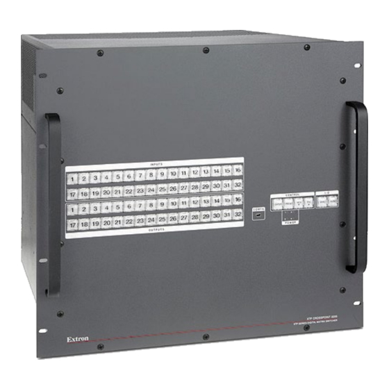
Guide Overview This guide contains installation, configuration, and operating information for the Extron XTP CrossPoint1600 Matrix Switcher (see figure 1) and XTP CrossPoint 3200 Matrix Switcher. These customizable matrix switchers support up to 16 (XTP CrossPoint1600) or 32 (XTP CrossPoint 3200) inputs and outputs. -
Page 10: Product Description
Product Description The XTP CrossPoint Series matrix switchers are configurable, modular switchers that distribute a variety of video, audio, and data types, depending on its configuration. A matrix switcher routes any input signal to any combination of outputs. It can route multiple signals at once. -
Page 11: Endpoint Configuration
• XTP CrossPoint 3200 — 10U high The base XTP CrossPoint1600 ships with two internal power supplies on a single AC connection that provide 12 V and 48 V. It can be ordered with two additional optional redundant (12 V and 48 V) power supplies. The customer cannot install the redundant power supplies. -
Page 12: Input And Output Board And Signal Types
Input and Output Board and Signal Types The XTP CrossPoint Series matrix switchers are assembled from user-installed and hot-swappable input and output boards. This section details the signal types processed by each board and the function of boards. The boards have a primary signal type that is identified by the name of the board and used as the subsections of the Primary signal type, by board section starting on the next... - Page 13 Primary signal type, by board XTP input and output boards The XTP boards are essentially receivers (input boards) and transmitters (output boards). The input board receives up to four XTP inputs, on either Extron XTP DTP 24 SF/UTP cable or shielded Category 5e, 6, or 7 (CAT x) shielded twisted pair (STP) cable, terminated with RJ-45 connectors, from Extron XTP transmitters.
- Page 14 HDMI input boards and DVI Pro input boards both also have four analog balanced stereo inputs on captive screw connectors (see Analog audio inputs on the next page). HDMI output boards and DVI Pro output boards both also have four analog balanced stereo Analog audio outputs outputs on captive screw connectors (see on the next page).
-
Page 15: Features
Secondary signal type Serial port inserts The XTP and fiber input and output boards also have four local RS-232 and IR insert inputs on captive screw connectors. The insert inputs support up to a 115k baud rate. Each RS-232 and IR insert and local output is for the associated input or output only and cannot be tied to other outputs or inputs. - Page 16 Remote power to XTP transmitters and receivers — To simplify installation in • space-challenged locations, an XTP CrossPoint Series matrix switcher can provide power to remote XTP transmitters and receivers over the same STP cable that is used for sending AV signals. This avoids the need for external power supplies at remote endpoints.
- Page 17 Automatic cable equalization for each digital input to 100 feet (30 m) when • used with Extron HDMI or DVI Pro cables — Cable input equalization optimizes signal performance for all incoming signals, ensuring pristine image quality is delivered throughout an XTP CrossPoint System. •...
- Page 18 Internal universal power supply — The 100-240 VAC, 50/60 Hz, international power • supply provides worldwide power compatibility. Primary and redundant power supplies — Redundant power supplies (optional • for the XTP CrossPoint 1600, standard for the XTP CrossPoint 3200) are available for continuous, mission-critical applications where power reliability is crucial.
-
Page 19: Installation
Installation This section details the installation and configuration of the XTP CrossPoint Series matrix switchers, including: • Setup and Installation Checklist • Rear Panel Cabling and Features Front Panel Configuration Port and Power LEDs • Setup and Installation Checklist Get ready Familiarize yourself with the XTP CrossPoint Series matrix switcher. -
Page 20: Rear Panel Cabling And Features
Rear Panel Cabling and Features Figure 2 shows an XTP CrossPoint 1600. Figure 3 on the next page shows an XTP CrossPoint 3200. The models have similar features, but different-sized enclosures and a different arrangement of the features. XTP CROSSPOINT 1600 1−4 1−4 1−4... - Page 21 C DE XTP CrossPoint 3200 INPUTS OUTPUTS 9-12 13-16 17-20 21-24 25-28 29-32 9-12 13-16 17-20 21-24 25-28 29-32 REMOTE 9 13 17 21 25 29 8 12 16 20 24 28 32 RESET 9 13 17 21 25 8 12 16 20 24 28 32 DISCONNECT POWER CORD BEFORE SERVICING...
-
Page 22: Input And Output Boards
Input and Output Boards On the XTP CrossPoint 1600, the top slots are for input boards and the bottom slots are for output boards. On the XTP CrossPoint 3200, slots on the left are for input boards and slots on the right are for output boards. Each board installed in a slot supports up to four inputs or outputs of the applicable type (see Input and Output Boards and Signal Types page 4,... - Page 23 LAN (Ethernet connectors — As desired, connect a TP cable between a host device or control LAN and this connector for passive extension to the LAN (Ethernet connector on the connected endpoint (see TP connectors on page 19 to wire the connector).
- Page 24 XTP CP 4i DVI Pro (DVI Pro input board) XTP CP 4i DVI Pro AUDIO Figure 8. DVI Pro Input Board Connectors NOTE: Although the DVI Pro boards use DVI-I connectors, the matrix switchers handle only DVI-D (digital) video. Input connectors — Connect a DVI cable between this port and the DVI output port of the digital video source (see DVI connectors on page 23 for pin...
- Page 25 Output boards space — NOTE: See figure 2 on page 12 and figure 3 on page 13. Install output boards as desired in output slots 1 through 4 (XTP CrossPoint 1600), slots 1 through 8 (XTP CrossPoint 3200) and make connections. See Installing the Input or Output Board or Blank Panel on page 147 and the individual board...
- Page 26 XTP CP 4o Fiber 4K (fiber optic output board) OUTPUTS XTP OUT XTP OUT XTP OUT XTP OUT OVER FIBER XTP CP 4o FIBER 4K RS-232 RS-232 RS-232 RS-232 LINK LINK LINK LINK Tx Rx G Tx Rx Tx Rx G Tx Rx Tx Rx G Tx Rx Tx Rx G Tx Rx Figure 12.
- Page 27 XTP CP 4o DVI Pro (DVI Pro Output board) XTP CP 4o DVI Pro AUDIO Figure 15. DVI Pro Output Board Connectors NOTE: Although the DVI Pro boards use DVI-I connectors, the matrix switchers handle only DVI-D (digital) video. Output connector — Connect a DVI cable between this port and an DVI video display (see DVI connectors on page 23 for pin assignments).
-
Page 28: Green
The cable used depends on your network speed. The matrix switcher LAN port supports both 10 Mbps (10Base-T — Ethernet) and 100 Mbps (100Base-T — Fast Ethernet), half-duplex and full-duplex Ethernet connections. Input and output boards support 100Base-T only. • 10Base-T Ethernet requires CAT 3 UTP or STP cable at minimum. - Page 29 XTP board XTP ports — The XTP input boards and output boards are compatible with shielded twisted pair (F/UTP, SF/UTP, and S/FTP) and unshielded twisted pair (U/UTP) cables. ATTENTION: • Do not connect these boards to a computer data or telecommunications network. •...
-
Page 30: Pins: 1 2 3 4 5 6 7
RS-232 and IR connectors Figure 18 shows how to wire the RS-232 and IR connector. IR Device Tx/Rx Pins RS-232 Device Figure 18. RS-232 and IR Connector Wiring NOTES: • The length of exposed wires is critical. The ideal length is 3/16 inch (5 mm). •... -
Page 31: Green
ATTENTION: • Do not overtighten the HDMI connector mounting screw. The shield it fastens to is very thin and can easily be stripped. • Ne serrez pas trop la vis de montage du connecteur HDMI. Le blindage auquel elle est attachée est très fin et peut facilement être dénudé. Loosely place the included tie wrap around the HDMI connector and the LockIt lacing bracket as shown ( While holding the connector securely against the lacing bracket, use pliers or similar... - Page 32 Analog audio input connectors Connectors are included with the matrix switcher, but you must supply the audio cable. See figure 23 to wire a connector for the appropriate input type. Use the supplied tie-wrap to strap the audio cable to the extended tail of the connector. High impedance is generally over 800 ohms.
- Page 33 Analog audio output connectors Connect audio devices, such as an audio amplifier or powered speakers, to these 3.5 mm, 5-pole captive screw connectors. These connectors output the tied unamplified, line level audio. See figure 25 to wire an output connector. Use the supplied tie-wrap to strap the audio cable to the extended tail of the connector.
-
Page 34: Remote Control Ports
Remote Control Ports Remote RS-232/RS-422 port (see figure 2 figure 3 on page 12 and page 13) — Connect a host device, such as a computer or touchpanel control, to the matrix switcher via this 9-pin D connector for serial RS-232 or RS-422 control (see figure 26). -
Page 35: Reset Button And Led
Reset Button and LED Reset button (see figure 2 figure 3 on page 12 and on page 13) — The RESET button initiates four levels of matrix switcher reset. For resets, press and Reset hold the button while the matrix switcher is running or while you power up the matrix switcher (see Rear Panel Operations on page 62 for details). - Page 36 Power LEDs — NOTES: • The XTP CrossPoint 3200 has four power supplies installed. These power supplies are indicated by the following LEDs: • LEDs 1 and 2 — Indicate the status of the two primary 12 V supplies. • LED 3 —...
-
Page 37: Operation
Operation This section describes the front panel operation of the XTP CrossPoint Matrix Switcher, including: • Front Panel Controls and Indicators • Front Panel Operations Rear Panel Operations • • Optimizing the Analog Audio RS-232 Insertion • • Troubleshooting • Configuration Worksheets Front Panel Controls and Indicators The front panel controls (see figure 28 and... - Page 38 CD EF G H INPUTS 1 2 3 4 5 6 7 8 9 10 11 12 14 15 16 17 18 19 20 21 22 23 24 25 26 27 28 30 31 32 1 2 3 4 5 6 7 8 9 10 11 12 14 15 16 CONTROL AUDIO...
-
Page 39: Input And Output Buttons
Input and Output Buttons NOTES: • Input and output buttons cannot select an input or output number that is higher than your matrix size or if the board that supports it is not installed. Unselectable buttons do have other functions as described in the following pages. •... -
Page 40: Control Buttons
Control Buttons NOTE: See Front Panel Operations, beginning on page 35, for detailed descriptions of the following operations. Primary functions Action Save changes Select Preset mode Select View mode Cancel or Escape Indication Blink: Save needed Blink: Save preset View mode Blinks once Lit: Recall preset selected... - Page 41 View ( ) button (see figure 28 on page 29 or figure 29 on page 30) — The < View ) button has one primary function (…) and six secondary functions (•): < Select and indicate View-only mode, which displays the current configuration. …...
-
Page 42: I/O Controls
I/O Controls NOTE: See Front Panel Operations, beginning on page 35, for detailed descriptions of the following operations. Primary functions Action Select video Select audio Indication Green: selected Red: selected VIDEO AUDIO Secondary functions Resets Action 1: Perform a system reset. Port Action Select RS-232. -
Page 43: Button Icons
Button Icons The numbered translucent covers on the input and output buttons can be removed and replaced to insert labels behind the covers. Input and output labels can be created easily with the Extron Button-Label Generator software, which is shipped with every Extron matrix switcher. Each input and output can be labeled with names, alphanumeric characters, or color bitmaps for easy and intuitive input and output selection (see figure 30). -
Page 44: Definitions
Definitions The following Extron matrix switcher terms are used throughout this guide: Tie — An input-to-output connection Set of ties — An input tied to two or more outputs. NOTE: An output can never be tied to more than one input. Configuration —... -
Page 45: Creating A Configuration
Creating a Configuration The current configuration can be changed using the front panel buttons. Change the current configuration as follows: Press the button to clear any input button indicators, output button indicators, or control button indicators that may be lit. Press the button and button as necessary to select video, audio, or both... - Page 46 Example 1: Create a set of video and audio ties Clear all selections: Press and release Press the Esc button to clear all selections. C O N T R O L VIEW ENTER PRESET The button flashes once. Select video and audio for the tie: If necessary, press and release Video Audio to light both.
- Page 47 The current configuration (see figure 31) is now input 5 video and audio are tied to output 3, output 4, and output 8. Input 5 (video and audio) tied to outputs 3, 4, and 8 Input Output Video Audio Figure 31. Final Configuration, Example 1 Example 2: Add a video tie to a set of video and audio ties In the following example, a new video tie is added to the current configuration.
- Page 48 The current configuration (see figure 32) is now: • Video — Input 5 video is tied to output 1, output 3, output 4, and output 8. Audio — Input 5 audio is tied to output 3, output 4, and output 8. •...
-
Page 49: Viewing The Configuration
Select the output: Press and release Output 4 C O N T R O L Press the button. The button blinks red to indicate the pending change: VIEW ENTER PRESET audio input will be untied. The Enter button blinks OUTPUTS green to indicate the need to 8 15 16 confirm the change. - Page 50 Select the desired input or outputs whose ties you wish to view by pressing the input and output buttons. NOTES: • To see all ties of the current configuration, press and release each input and output button, one at a time, with the button and the button lit.
- Page 51 NOTE: You can also view a set of ties by selecting a tied output. Demonstrate this as follows: • Note the number of a lit output button, and then press and release the output button for an untied (unlit or background illumination) output. •...
-
Page 52: Using Presets
Using Presets The current configuration (configuration ) can be saved as a preset in any one of 32 preset memory locations. All 32 presets are assigned to the input buttons and (where necessary) output buttons and are available to be either saved or retrieved from the front panel. When a preset is recalled from memory, it becomes the current configuration. - Page 53 Select the preset: Press and release the input or output button for the desired preset. C O N T R O L Press the button. VIEW ENTER PRESET The button blinks to indicate that this preset number is selected but not saved. •...
-
Page 54: Muting And Unmuting Video And Audio Outputs
Muting and Unmuting Video and Audio Outputs Individual outputs can be muted or unmuted as follows: NOTE: Output mutes are protected when front panel Lock mode 2 is selected. You can view the status of the output (muted or unmuted) in Lock mode 2 but you cannot change it from the front panel (see Setting the Front Panel Locks (Executive Modes) - Page 55 Press the Video button Press the Audio button I / O to toggle on and off. to toggle on and off. VIDEO AUDIO The button lights green The button lights red when selected. when selected. Until you select an input, the buttons for all untied outputs light amber if no inputs are tied, green if no video inputs are tied (only audio is tied), or red if no audio are tied (only video is tied).
-
Page 56: Viewing And Adjusting The Input Audio Level
Mute outputs: One at a time: Press and hold the button for approximately 2 seconds until the button Output 3 returns to its previous state. The output 3 video and audio signals are unmuted. Press and hold the button for approximately 2 seconds until the button Output 4 returns to its previous state. - Page 57 Press the button to clear any input buttons, output buttons, or control buttons that may be lit. Press and hold the button until the button begins to blink red to enter Audio Audio mode. Release the button. Press and release an input button to select an input that has analog audio. The output buttons display the audio level for the selected input;...
- Page 58 Output LED Indication Output LED Indication 9 10 11 12 13 14 15 16 9 10 11 12 13 14 15 16 18 19 20 21 22 23 24 25 26 27 28 29 30 31 32 18 19 20 21 22 23 24 25 26 27 28 29 30 31 32 9 10 11 12 13 14 15 16...
- Page 59 Output LED Indication 9 10 13 14 15 16 9 10 13 14 15 16 9 10 13 14 15 16 9 10 13 14 15 16 11 12 13 14 15 16 9 10 9 10 11 12 13 14 15 16 13 14 15 16...
- Page 60 Example 8: Viewing and adjusting an input audio level Because of the different gain and attenuation display schemes, the input audio levels that result from the following example are shown two times: As displayed on an XTP CrossPoint 3200 matrix switcher •...
- Page 61 Change the audio level: Press and release the ) button once (see figure 38) to View < decrease the input audio level by 1 dB. Press and release the ) button several more times (see figure 36) to decrease < View the input audio level by 1 dB per button press.
-
Page 62: Viewing And Adjusting The Analog Output Volume
Viewing and Adjusting the Analog Output Volume The level of each analog audio output can be displayed and adjusted through a range of 100% (no attenuation) to 0% (maximum [76 dB] attenuation). The audio level can be adjusted from the front panel or under serial port, USB port, or Ethernet control. The default volume is 100% (no attenuation). - Page 63 For each display scheme, the input buttons blink or light sequentially to indicate the approximate volume of the selected output. Volume is defined as a percentage of the input audio signal that is applied to the output. From 0% of volume, the first ) button push applies 5.5% >...
- Page 64 Highest # input button lit Highest # input button lit dB of Output dB of Output XTP CrossPoint 1600 XTP CrossPoint 3200 attenuation volume XTP CrossPoint 1600 XTP CrossPoint 3200 attenuation volume None None 5.5% 53.5% 8.5% 56.5% 11.5% 59.5% 14.5% 62.5% 17.5%...
- Page 65 Example 9: Viewing and adjusting an analog output volume level In the following example, the audio output volume is viewed and adjusted. The steps show the front panel indications that result from your action. Because of the different volume display schemes, the output audio levels that result from the following example are shown twice: •...
- Page 66 Change the volume: Press and release the ) button once (see figure 42) to > increase the volume by 1.5%. Press and release the ) button several more times (figure 42) to increase the > volume by 1.5% per button press. Note the input button indication changes that occur each time the ) button is pressed and released.
-
Page 67: Setting The Front Panel Locks (Executive Modes)
Setting the Front Panel Locks (Executive Modes) The matrix switcher has three levels of front panel security lock that limit the operation of the matrix switcher from the front panel. The three levels are: • Lock mode 0 — The front panel is completely unlocked. All front panel functions are available. -
Page 68: Performing A System Reset From The Front Panel
Selecting Lock mode 2 or toggling between mode 2 and mode 1 NOTE: • If the matrix switcher is in Lock mode 0 or mode 1, this procedure selects mode 2. • If the matrix switcher is in Lock mode 2, this procedure selects mode 1. Toggle the lock on and off by pressing and holding the button and the button... -
Page 69: Background Illumination
Background Illumination The buttons on the front panel can be set to provide amber background illumination at all times or the background illumination can be turned off. To toggle the background illumination on or off, press and hold the buttons simultaneously for Input 1 Input 2 approximately 2 seconds (see figure 47). -
Page 70: Rear Panel Operations
Exit the Serial Port Configuration mode: Press and release an output button. All Control and I/O buttons return Press and release to unlit or background illumination. an output button. I / O C O N T R O L VIEW ENTER PRESET VIDEO... - Page 71 Hold down the button twice Mode 4: Mode 4 enables Reset (once at 3 seconds and again at 6 you to set • Enables ARP capability. seconds). Then press and release IP address • Sets the IP address to the factory default. (<1 second) within 1 second.
-
Page 72: Performing A Hard Reset (Reset 1)
Performing a Hard Reset (Reset 1) The hard reset function restores the matrix switcher to the base firmware that it was shipped with. After a hard reset, events do not automatically start, but user settings and files are restored. Perform a hard reset as follows: NOTE: The hard reset restores the factory-installed firmware. -
Page 73: Performing Soft System Resets (Resets 3, 4, And 5)
Performing Soft System Resets (Resets 3, 4, and 5) Perform a soft reset of the matrix switcher as follows: Use a small screwdriver to press and hold the rear panel button until the Reset Reset LED and the front panel buttons blink the number of times for the Video Audio... -
Page 74: Optimizing The Analog Audio
Optimizing the Analog Audio The level for each analog audio input can be adjusted within a range of -18 dB to +24 dB, so there are no noticeable volume differences between sources and for the best headroom and signal-to-noise ratio. The volume for each analog audio output can be adjusted from full loudness to effectively muted. -
Page 75: Ethernet To Rs-232 Insertion
Ethernet to RS-232 Insertion Figure 50 is an example of a typical Ethernet to RS-232 insertion, in which an Extron IPCP module provides control of an HD camera via the matrix switcher. Configure this type of insertion as follows: Connect a TP cable from the IPCP module to the LAN port, directly or via a network. If necessary, enable the port (input port 4 in this example) for Ethernet (see Enabling Ethernet and Captive Screw Insertion... - Page 76 UART Default Values Port 1600 3200 Port 1600 3200 Serial 1999 Input 1 2001 Output 1 2033 Input 2 2002 Output 2 2034 Input 3 2003 Output 3 2035 Input 4 2004 Output 4 2036 Input 5 2005 Output 5 2037 Input 6 2006...
-
Page 77: Captive Screw Signal Insertion
Changing the starting point You can change the starting port number. The simplest way to make this change is using the XTP Configuration Software. Alternatively, you can change the starting port number via SIS commands. • For the input XTP and fiber boards, see the input board Set UART starting point SIS command on page 92. -
Page 78: Troubleshooting
Connect a serial cable from the endpoint to the device to be controlled. IPCP RS-232 Module Insertion LINK LINK LINK LINK XTP CP 4i IR/RS-232 OVER XTP RS-232 RS-232 RS-232 RS-232 RS-232 1−4 LINK LINK LINK LINK Tx Rx Tx Rx Tx Rx Tx Rx Tx Rx... -
Page 79: Configuration Worksheets
Configuration Worksheets Rather than trying to remember the configuration for each preset, use worksheets to record this information. Make copies of the blank worksheet on page 74 (XTP CrossPoint 3200) or page 75 (XTP CrossPoint 1600) and use one for each preset configuration. Cross out all unused or inactive inputs and outputs. -
Page 80: Worksheet Example 2: Daily Configuration
Worksheet Example 2: Daily Configuration Figure 53 continues from worksheet example 1 by showing the video and audio ties that make up the configuration of preset 1. Black lines show video ties and red lines show the audio ties. Input sources Camera/ Camera PC 1... -
Page 81: Worksheet Example 3: Test Configuration
Worksheet Example 3: Test Configuration The AV system in our fictional organization needs to be fine tuned on a regular basis. Figure 54 shows a typical test configuration, with an Extron video test generator (input 12) generating a test pattern to all monitors (outputs 1, 2, 3, and 8). Sound checks are run from the CD player (input 5) to all audio systems (outputs 1, 2, 4, 5, and 8). -
Page 82: Xtp Crosspoint 3200 Matrix Switchers Configuration Worksheet
XTP CrossPoint 3200 Matrix Switchers Configuration Worksheet XTP CrossPoint Series • Operation... -
Page 83: Xtp Crosspoint 1600 Matrix Switchers Configuration Worksheet
XTP CrossPoint 1600 Matrix Switchers Configuration Worksheet XTP CrossPoint Series • Operation... -
Page 84: Programming Guide
Programming Guide The XTP CrossPoint Series Matrix Switcher can be remotely controlled via: • The XTP System Configuration software (see the XTP System Configuration Software Help file, available at www.extron.com). • Built-in HTML pages (see HTML Operation, beginning on page 121) SIS commands (see below) •... -
Page 85: Local Host-Control Ports
Local Host-Control Ports The matrix switcher has two local ports that can be directly connected to a host device such as a computer running the Extron DataViewer utility or a control system. These ports make remote control of the matrix switcher possible using a direct connection. The local ports are: •... -
Page 86: Establishing A Connection
Establishing a Connection Establish a network connection to an XTP CrossPoint Series matrix switcher as follows: Open a TCP socket to port 23 using the IP address of the matrix switcher. NOTE: If the local system administrators have not changed the value, the factory-specified default, 192.168.254.254, is the correct value for this field. -
Page 87: Host-To-Matrix-Switcher Instructions
The matrix switcher does not expect a response from the host, but, for example, the host program might request a new status. (c) Copyright 20yy, Extron Electronics, XTP CP nn00, Vx.xx, 60-nnnn-01 <day, date, time> The matrix switcher initiates the... -
Page 88: Matrix Switcher Error Responses
Outnn • Volxx The matrix switcher initiates the message when a front panel output audio volume change has occurred. is the output number and is the volume level. Vmtnn*x The matrix switcher initiates the message when an output video mute is toggled on or off from the front panel. -
Page 89: Arrangement Of Command And Response Tables
Arrangement of Command and Response Tables Different board types and endpoint types accept different types of commands. There is some repetition in the command and response tables, depending on the input and output for which the commands are appropriate. Additionally, basic whole-matrix-switcher commands, more advanced whole-matrix-switcher commands, and IP- and remote port setup commands are presented in separate command and response tables. - Page 90 Input boards Input Endpoints Command Fiber 4K HDMI DVI Pro XTP T HDMI XTP T USW 103 XTP T VGA XTP T FB 202 family XTP 4K HDMI HD-SDI XTP T HD 4K XTP T USW 103 4K XTP T FB 202 4K HDMI DMA XTP T HWP 101 XTP T UWP 202...
-
Page 91: Symbol Definitions
Output boards Output endpoints Command Fiber 4K HDMI DVI Pro Analog XTP R HDMI XTP SR HDMI family XTP 4K HDMI audio XTP R HD 4K XTP SR HD 4K XTP R HWP 201 XTP SFR HD 4K XTP R HWP 201 4K XTP FR HD 4K Audio routing selections Page 103... - Page 92 = Port number = remote RS-232/RS-422 port = unused = Baud rate 1200 1800 2400 3600 4800 7200 9600 14400 19200 28800 38400 57600 115200 X1& = Parity = odd = even = none (default) = mark = space = Data bits (default) = Stop bits (default),...
- Page 93 = Detected video format = no signal detected = video = s-video = RGBcvS (SCART) = YUV interlace = RGB = YUV = Picture adjustments = default) = Shift 65535 = Analog input preset through = Output audio source = original HDMI audio = embed audio = HDCP status (for outputs) , or...
- Page 94 = Name 12 characters maximum NOTE: The HTML language reserves certain characters for specific functions Special Characters (see on page 120). = Lock mode = mode 0 = mode 1 = mode 2 (default) = Number of inputs , or = Number of outputs , or = Installed input board...
-
Page 95: Sis Command And Response Table For Basic Matrix Switcher Commands
SIS Command and Response Table for Basic Matrix Switcher Commands The table that starts below shows commands for basic operation of the XTP CrossPoint Series matrix switcher frame. Commands shown affect the entire matrix switcher, regardless of the input boards and output boards installed or any connected endpoints. Command Function SIS Command Response... -
Page 96: Sis Command And Response Table For Input-Board-Specific Commands
SIS Command Response Additional Description Command Function (Host to Unit) (Unit to Host) Read ties NOTE: The read tie command for RGB and the read tie command for video can be used interchangeably on the matrix switchers. & Read RGB (video) output tie RGB input is tied to output &... - Page 97 XTP CrossPoint Series • Programming Guide...
- Page 98 XTP CrossPoint Series • Programming Guide...
- Page 99 SIS Command Response Additional Description Command Function (Host to Unit) (Unit to Host) Input sync detection View all input connections s; each is the connection 16 or 32 status of an input, starting from input 1. Example Sync detected Sync detected No input detected (XTP CrossPoint 3200): 0 0 0 1 1 1 0 1 0 0 1 0 1.
- Page 100 SIS Command Response Additional Description Command Function (Host to Unit) (Unit to Host) Inputs on XTP CP 4i HD 4K PLUS, XTP CP 4i HDMI, XTP CP 4i HDMI DMA, and XTP CP 4i DVI Pro Boards (continued) HDCP status X1#] View input HDCP status HDCP...
- Page 101 SIS Command Response Additional Description Command Function (Host to Unit) (Unit to Host) Inputs on XTP CP 4i [XTP] and XTP CP 4i 4K [XTP] Boards XTP power ATTENTION: • Power over XTP (PoX) is intended for indoors use only. No part of a network that uses PoX can be routed outdoors. •...
- Page 102 SIS Command Response Additional Description Command Function (Host to Unit) (Unit to Host) Inputs on XTP CP 4i VGA (Analog Video) Boards Input video format Set format X3)] Set input video format. The Ityp board reports the detected video format, , in the response.
- Page 103 SIS Command Response Additional Description Command Function (Host to Unit) (Unit to Host) Inputs on XTP CP 4i VGA (Analog Video) Boards (continued) Pixel phase NOTE: Pixel phase adjustments are available for RGBHV and non-interlaced component video (YUVp) video inputs. Set a specific pixel sampling phase X3!] Specify the pixel sampling phase.
-
Page 104: Sis Command And Response Table For Input-Endpoint-Specific Commands
SIS Command and Response Table for Input-Endpoint-Specific Commands The table that starts below shows commands that affect the following endpoints connected through XTP input boards only. XTP T HDMI and XTP T HD 4K XTP T UWP 202 and XTP T UWP 202 4K •... - Page 105 SIS Command Response Additional Description Command Function (Host to Unit to Endpoint) (Endpoint to Unit to Host) XTP T HDMI , XTP T HD 4K, XTP T HWP 101, XTP T HWP 101 4K, and XTP FT HD 4K transmitter commands Audio routing selections X1!] Input audio selection...
- Page 106 SIS Command Response Additional Description Command Function (Host to Unit to Endpoint) (Endpoint to Unit to Host) XTP T USW 103 and XTP T USW 103 4K switcher commands Select an endpoint switcher input Select an input Select input on input *3ETIE Etie video...
- Page 107 SIS Command Response Additional Description Command Function (Host to Unit to Endpoint) (Endpoint to Unit to Host) XTP T USW 103 and XTP T USW 103 4K switcher commands (continued) Audio routing selections Enable black signal for XTP T Enable an audio only tie for the *1AFMT AfmtE endpoint...
- Page 108 SIS Command Response Additional Description Command Function (Host to Unit to Endpoint) (Endpoint to Unit to Host) XTP T VGA transmitter commands (continued) Color NOTE: Color adjustments are available for RGBcvS (SCART), interlaced component video (YUVi), S-video, and NTSC composite video inputs.
- Page 109 SIS Command Response Additional Description Command Function (Host to Unit to Endpoint) (Endpoint to Unit to Host) XTP T VGA transmitter commands (continued) Horizontal shift Specify a value X3@] Set the horizontal location of first active HCTR HctrI pixel in input X3@] Increment value Increase the value by one pixel (shift the...
- Page 110 SIS Command Response Additional Description Command Function (Host to Unit to Endpoint) (Endpoint to Unit to Host) XTP T FB 202, XTP T FB 202 4K, XTP T UWP 202, XTP T UWP 202 4K, and XTP T UWP 302 switcher commands (continued) HDCP status X1#]...
-
Page 111: Sis Command And Response Table For Output-Board-Specific Commands
SIS Command and Response Table for Output-Board-Specific Commands The table that starts below shows commands that affect outputs only and, in general, apply to installed output boards. Where a command does not apply to all output board types, the valid board types are noted. Command Function SIS Command Response... - Page 112 SIS Command Response Additional Description Command Function (Host to Unit) (Unit to Host) Outputs on XTP CP 4o HD 4K PLUS, XTP CP 4o HDMI, XTP CP 4o DVI Pro, and XTP CP 4o SA Boards Audio output volume NOTE: The table below the commands defines the value of each audio volume step. X3^] Set a specific audio volume •Vol...
- Page 113 SIS Command Response Additional Description Command Function (Host to Unit) (Unit to Host) XTP CP 4o HD 4K PLUS, XTP CP 4o DVI Pro,and XTP CP 4o SA Boards (cont) Outputs on XTP CP 4o HDMI, Audio mutes Mute digital audio Mute output digital audio (audio off).
- Page 114 SIS Command Response Additional Description Command Function (Host to Unit) (Unit to Host) Outputs on XTP CP 4o [XTP], XTP CP 4o 4K [XTP], and XTP CP 4o Fiber 4K Boards (continued) Ethernet serial port insert parameters (continued) EX2! X2!] Set UART starting point Sets the initial (lowest) port number for the range of numbers assigned to the serial...
-
Page 115: Sis Command And Response Table For Output-Endpoint-Specific Commands
SIS Command and Response Table for Output-Endpoint-Specific Commands The table that starts below shows commands that affect XTP R HDMI, XTP R HD 4K, XTP R HWP 201, XTP R HWP 201 4K, XTP SR HDMI, XTP SR HD 4K, XTP FR HD 4K, and XTP SFR HD 4K endpoints connected through an XTP board only. - Page 116 SIS Command Response Additional Description Command Function (Host to Unit to Endpoint) (Endpoint to Unit to Host) XTP R HDMI, XTP R HD 4K, and XTP FR HD 4K receiver commands (continued) HDCP status View output HDCP status X3%] HDCP View HDCP status of all outputs n = either OHDCP...
- Page 117 SIS Command Response Additional Description Command Function (Host to Unit to Endpoint) (Endpoint to Unit to Host) XTP SR HDMI, XTP SR HD 4K, and XTP SFR HD 4K scaler commands (continued) Audio routing selections NOTES: • These commands select between the audio embedded in the digital video stream and the 2-channel analog audio. •...
- Page 118 SIS Command Response Additional Description Command Function (Host to Unit to Endpoint) (Endpoint to Unit to Host) XTP SR HDMI, XTP SR HD 4K, and XTP SFR HD 4K scaler commands (continued) Relay controls Turn on an endpoint relay Turn on relay in output *1RELY Rely...
-
Page 119: Sis Command And Response Table For Advanced Matrix Switcher Commands
SIS Command and Response Table for Advanced Matrix Switcher Commands The table that starts below shows commands for advanced operation of the XTP CrossPoint Series matrix switcher frame. Commands shown affect the entire matrix switcher, regardless of the input boards and output boards installed or any connected endpoints. SIS Command Response Additional Description... - Page 120 SIS Command Response Additional Description Command Function (Host to Unit) (Unit to Host) Save and directly write global presets Save current configuration as a PRST PrstS global preset Example: Save current ties as preset 8. S8PRST PrstS08 Direct write process — NOTE: The direct write of a global preset should always be preceded by a clear global preset ties command of that same preset number, as shown below.
- Page 121 SIS Command Response Additional Description Command Function (Host to Unit) (Unit to Host) View ties, gain, volume, mutes, presets, and power usage Read RGB (video) output tie Video input is tied to output & Example: Input 12 RGB is tied to output 5. 5&...
- Page 122 SIS Command Response Additional Description Command Function (Host to Unit) (Unit to Host) View ties, gain, volume, mutes, presets, and power usage (continued) View audio global preset *2VC • • • •...• •Aud n+15 configuration Show the audio configuration for preset Show the input tied to 16 sequential outputs, starting from output Command description:...
- Page 123 SIS Command Response Additional Description Command Function (Host to Unit) (Unit to Host) Information requests Information request X4^] V (video) matrix size•A (audio) matrix size •A Request part number See the Extron Website for part numbers. -nnnn-nn Request input/output board X4&...
- Page 124 SIS Command Response Additional Description Command Function (Host to Unit) (Unit to Host) Information requests (continued) Request system status See below XTP CrossPoint 3200: X5$X5$X5$X5$] • • • • • • • • • • • • • X5$X5$] XTP CrossPoint 1600 (no redundant power supply): •...
- Page 125 = Time and date (for read) In the format: Day, • • • YYYY • HH:mm:SS where: = day of the week: = day: = month: = year: YYYY 2000 2099 = hour: = minute: = second: = GMT offset (hours and minutes removed from -12.0 +14.0...
- Page 126 = Port number = Remote RS-232/RS-422 port = Unused = UARTs 1-64 (XTP input and output board ports) = Baud rate (default), 9600 19200 38400 115200 = Parity = odd = even = none (default) = mark = space = Data bits (default) = Stop bits (default),...
-
Page 127: Sis Command And Response Table For Ip- And Remote Port-Specific Commands
SIS command and Response Table for IP- and Remote Port-Specific Commands Command Function SIS Command Response Additional Description (Host to Unit) (Unit to Host) IP and Remote port setup commands EX6! X6!] Set matrix name Ipn• X6!] Read matrix name (location) X6@] Reset matrix name to factory default •CN... -
Page 128: Special Characters
Command Function SIS Command Response Additional Description (Host to Unit) (Unit to Host) EX7* X7*] Set DHCP on or off Default: 0 (Off) X7*] Read DHCP on/off status IP and Remote port setup commands (continued) EX7( Set serial port parameters X8#] •Ccp EX7(... -
Page 129: Html Operation
HTML Operation The XTP CrossPoint Series can be remotely controlled via: • The XTP System Configuration Software (see the XTP System Configuration Software help file, available at www.extron.com). • SIS commands (see Programming Guide, beginning on page 76) Built-in HTML pages (see below) •... -
Page 130: Download The Startup Page
Download the Startup Page Access the matrix switcher using HTML pages as follows: Start the Web browser program. Click in the field of the browser and highlight any existing text. Address Enter the Matrix IP address in the field of the browser. Address NOTE: If the local system administrators have not changed the value, the factory-specified default, 192.168.254.254, is the correct value for this field. -
Page 131: Status Tab
Status Tab System Status Page page (see figure 56) provides an overall view of the status of the matrix System Status switcher, including individual voltages, fan operation, and the serial port status. The System page is the default page that the matrix switcher downloads when you connect Status to the matrix switcher. -
Page 132: Dsvp Page
DSVP Page page (see figure 57) provides the connection status of the matrix switcher. Access DSVP page from the page by clicking the link on either DSVP System Status HDCP DSVP page. System Status HDCP Figure 57. DSVP Page XTP CrossPoint Series • HTML Operation... -
Page 133: Hdcp Page
HDCP Page page (see figure 58) provides the HDCP status of inputs to and outputs from the HDCP matrix switcher. Access the page from the page by clicking HDCP System Status DSVP link on either the page. HDCP System Status DSVP Figure 58. -
Page 134: Configuration Tab
Configuration Tab System Settings Page The XTP CrossPoint Series matrix switcher downloads the page (see System Settings figure 59) when you click the tab ( ). The screen consists of fields in Configuration which you can view and edit IP administration and system settings. You can access the pages by clicking the appropriate link (see Ethernet Link Email Settings... -
Page 135: Subnet Mask Field
Unit Name field field (see figure 59 on the previous page, ) contains the name used as Unit Name the “from” information when the matrix switcher e-mails notification of its failed or repaired status. This name field can be any valid name, up to 24 alphanumeric characters. NOTE: The HTML language reserves certain characters for specific functions (see Special Characters on page 120). - Page 136 Date/Time Settings panel panel (see figure 60) provides a location for viewing and setting Date/Time Settings the time functions. Figure 60. Date/Time Settings Panel Change the date and time settings as follows: Click the drop-down list for the desired value (see figure 60, ).
-
Page 137: Passwords Page
Passwords Page Access the page (see figure 61) by clicking the link ( ) on the left of Passwords Passwords , or page. System Settings Email Settings Firmware Upgrade 192.168.254.254 192.168.254.254 Figure 61. Passwords Page NOTE: If the matrix switcher is password-protected, fields on this page can be edited only by people logged in as administrators. -
Page 138: Email Settings Page
Email Settings Page Reach the page by clicking the link (see figure 62, Email Settings Email Settings on the left of the , or page. The System Settings Passwords Firmware Upgrade Email page has fields for setting up the e-mail notification capabilities of the matrix Settings switcher. -
Page 139: Email Address Fields
Setting up SMTP authorization If desired, set the XTP CrossPoint to require SMTP authorization before accepting any e-mail as follows: Click (see figure 62 on the previous page, ). The button changes to Edit Save Check the check box ( ). -
Page 140: Firmware Upgrade Page
Firmware Upgrade Page NOTE: The page is only for replacing the matrix switcher firmware Firmware Upgrade To insert your own custom HTML pages, see File Management Page on page 136. page is for replacing the matrix switcher firmware. Access the Firmware Upgrade page by clicking the link (see figure 63,... - Page 141 Click the link (see figure on the previous page). Firmware Select the desired firmware file to download and click Download Click the desired letter to jump to the correct page of downloads. TIP: Filter By: Enter the requested personal information ( TIP: Click to eliminate step 4 in future downloads.
- Page 142 Folder where firmware is installed. Sample location only. Figure 65. Downloading Firmware Upgrade Files XTP CrossPoint Series • HTML Operation...
- Page 143 Click the tab (see figure 66, Configuration Figure 66. Firmware Upgrade Click the link ( Firmware Upgrade Click the button ( ). An open file window appears. Browse Navigate to the folder where you saved the firmware upgrade file and select it ( ATTENTION: •...
-
Page 144: File Management Tab
File Management Tab File Management Page To delete files such as user-supplied HTML pages from the matrix switcher or to upload your own files to the matrix switcher, click the tab (see figure 67, ). The File Management matrix switcher downloads the page. -
Page 145: Control Tab
Control Tab Set and View Ties Page You can create ties on the page. Access the page Set and View Ties Set and View Ties by clicking the tab (see figure 68, Control Figure 68. User Control Ties page The page consists of a matrix of input (rows) and output (columns) selection buttons of four different colors: •... -
Page 146: Input Adjustments Page
Input Adjustments Page page is a central location for changing how input video and audio Input Adjustments are processed and switched. Access the page by clicking the link Input Adjustments (see figure 69, ) on the left of the Set and View Ties Output Adjustments EDID , or... -
Page 147: Output Adjustments Page
Selecting audio breakaway NOTES: • Available for inputs on XTP CP 4i (XTP), XTP CP 4i 4K (XTP), XTP CP 4i Fiber 4K, XTP II CP 4i HD 4K PLUS, XTP CP 4i HDMI, XTP CP 4i HDMI DMA, and XTP CP 4i DVI Pro boards. - Page 148 Figure 70. Output Adjustments Page Possible adjustments include: • Allow Audio Only • Volume • Mute • Embedded Audio Select Changing the output volume level You can set the volume level for each analog audio output volume level from page. Volume is adjustable through a range of zero steps I/O Settings of attenuation (full attenuation, minimum volume) to 64 steps of attenuation (no attenuation, full volume).
- Page 149 Number dB of Output Number dB of Output Number dB of Output of Steps Attenuation Volume of Steps Attenuation Volume of Steps Attenuation Volume 5.5% 38.5% 71.5% 8.5% 41.5% 74.5% 11.5% 44.5% 77.5% 14.5% 47.5% 80.5% 17.5% 50.5% 83.5% 20.5% 53.5% 86.5% 23.5%...
-
Page 150: Edid Configuration Page
EDID Configuration Page page allows you to select the EDID for each installed input and EDID Configuration save the output 1 EDID to one of the user locations. Access the page by clicking the EDID link (see figure 71, ) on the left of the Configuration Set and View Ties Input... -
Page 151: Xtp Power Page
XTP Power Page page provides a location to enable and disable PoX for all XTP inputs and XTP Power outputs. Access the page by clicking the link (see figure 72, ) on XTP Power XTP Power the left of the Set and View Ties Input Adjustments Output Adjustments... -
Page 152: Global Presets Page
Global Presets Page You can save and recall global presets from the page. Access the Global Presets Global page by clicking the link (see figure 73, ) on the left of the Presets Presets Set and , or View Ties Input Adjustments Output Adjustments EDID Configuration... -
Page 153: Maintenance And Modifications
Maintenance and Modifications This section covers XTP CrossPoint Series matrix switcher topics, including: Mounting the Matrix Switcher • • Battery and Power Precautions Removing and Installing an Input or Output Board or Blank Panel • • Removing and Installing Button Labels ATTENTION: •... -
Page 154: Mounting Instructions
Mounting Instructions If desired, rack mount the matrix switcher as follows: Insert the unit into the rack, aligning the mounting bracket holes with those in the rack. Secure the matrix switcher to the rack using the supplied bolts. Battery and Power Precautions The matrix switchers are each provided with a permanently installed (factory-soldered in place) lithium battery. -
Page 155: Installing An Input Or Output Board Or Blank Panel
Align with Plastic Guides Align with Plastic Guides 90 ° 90° I Pro P CP P CP P CP IR/R P CP I Pro P CP P CP 1− P CP 5− P CP IR/R 9− −1 1− 5− 9− Knurled Knobs −1 T PO... -
Page 156: Removing And Installing Button Labels
By default, the Windows installation creates a folder for the software, as follows: 64-bit OS: • C:\Program Files (x86)\Extron\ButtonLabelGenerator • 32-bit OS: C:\Program Files\Extron\ButtonLabelGenerator The installation also places the Button Label Generator icon into a group or folder named “Extron Electronics.” XTP CrossPoint Series • Maintenance and Modifications... - Page 157 Using the Button-Label Generator software Click Start > Programs > Extron Electronics > Button Label Generator > . The Button-Label Generator window opens (see figure 77). Button Label Generator Figure 77. Extron Button-Label Generator Window In the selection box, choose the...
-
Page 158: Making Labels From Paper Templates
Making Labels from Paper Templates Figure 79 on the next page provides strips of blank button labels. If desired, copy them or cut them out, write button information in each button area as desired, and put them in the windows of the input or output buttons. Installing Labels in the Buttons Install new labels in the front panel buttons as follows: Remove the button from the matrix switcher;... - Page 159 XTP CrossPoint Series • Maintenance and Modifications...
-
Page 160: Ethernet Connection
Ethernet Connection This section provides a high level discussion of the Ethernet connection to the matrix switcher and a primer on the subject of subnetting. Topics that are covered, include: • Ethernet Link • Subnetting — A Primer Ethernet Link The rear panel Ethernet connector on the XTP CrossPoint Series matrix switcher can be connected to an Ethernet LAN or WAN. -
Page 161: Pinging To Determine The Extron Ip Address
Pinging to Determine the Extron IP Address The ping utility is available at the Command prompt. Ping tests the Ethernet interface between the computer and the XTP CrossPoint Series matrix switcher. Ping can also be used to determine the actual numeric IP address from an alias and to determine the Web address. -
Page 162: Configuring The Xtp Crosspoint Series Matrix Switcher For Network Use Via The Arp Command
Configuring the XTP CrossPoint Series Matrix Switcher for Network Use via the ARP Command The ARP (address resolution protocol) command tells your computer to associate the MAC (media access control) address of the XTP CrossPoint Series matrix switcher with the assigned IP address. -
Page 163: Connecting As A Telnet Client
Connecting as a Telnet Client The Microsoft Telnet utility is available from the prompt. Telnet allows you to input SIS commands to the XTP CrossPoint Series matrix switcher from the PC via the Ethernet link and the LAN. Access the prompt and start Telnet as follows: Search for in the taskbar (Windows 10) or the Start menu (Windows 10-Vista). -
Page 164: Escape Character And Esc Key
Escape character and Esc key When Telnet is first started, the utility advises that the Escape character is ‘ ’. Many Ctrl SIS commands include the keyboard key. Consequently, some confusion may exist <Esc> between the Escape character and the Escape key. The Telnet Escape character is a key combination, the key and the key pressed... -
Page 165: Subnetting - A Primer
Subnetting — a Primer It is not the purpose of this guide to describe TCP/IP protocol in detail. However, some understanding of TCP/IP subnetting (a subnet is a subset of a network — a set of IP devices that have portions of their IP addresses in common) is necessary in order to understand the interaction of the XTP CrossPoint Series matrix switcher and the mail server gateway. -
Page 166: Determining Whether Devices Are On The Same Subnet
Determining Whether Devices Are on the Same Subnet To determine the subnet, the IP address of the analog device is compared to the IP address of the remote device (see figure 85). The octets of each address are compared or not compared, depending on the value in the related subnet mask octet. - Page 167 Extron Electronics makes no further warranties either expressed or implied with respect to the product and its quality, performance, merchantability, or fitness for any particular use. In no event will Extron Electronics be liable for direct, indirect, or consequential damages resulting from any defect in this product even if Extron Electronics has been advised of such damage.
Need help?
Do you have a question about the XTP CrossPoint1600 and is the answer not in the manual?
Questions and answers