Table of Contents
Advertisement
Advertisement
Table of Contents

Related Manuals for Loma IQ2


Summary of Contents for Loma IQ2
- Page 1 Metal Detector User Guide...
- Page 2 Metal Detector User Guide...
- Page 3 The IQ2 Metal Detector and this documentation are copyright material. No part of this documentation may be reproduced, transmitted, transcribed, stored in a retrieval system, or translated into any language, or computer language in any form or by any means without the prior written permission of Spectrum Inspection Systems.
-
Page 4: Safety Warnings
Preface Safety warnings Listed below are all the safety warnings that are used in this manual. It is strongly recommended that personnel who are, or will be, responsible for either installing, maintaining or operating the equipment described in this manual should read and understand these warnings. - Page 5 OSHA or OHSA with regards to any equipment supplied, nor can Loma be held liable for penalty which may be assessed for failure to meet the requirements of the acts as interpreted by an authorised inspector. Loma, however, does...
- Page 6 Preface 12.USE OF EQUIPMENT IN WORK AREAS WHERE EXPLOSIVE ATMOSPHERES MAY OCCUR. CE Directive 94/9/EC – ATEX Directive – July 2003 (a) LOCATION OF EQUIPMENT. This equipment is certified as category 3D for use in zones designated 22 only. (b) INSTALLATION AND MAINTENANCE. Electrical enclosures should be inspected and maintained on a regular basis to prevent the build up of dust deposits and to ensure the integrity of seals.
- Page 7 Preface The following safety warnings relate to specific metal detectors in the IQ range. Pipeline detectors including filler specific versions 15.SECURITY WHEN STAND MOUNTED. Due to the high centre of gravity, care should be taken when moving a pipeline metal detector on a stand as the applied force and/or obstructions of the wheels may cause the machine to fall over.
- Page 8 Preface detector falling over. This could result in death or severe injury to an individual and/or severe damage to the detector. 22.HANDLING WITH A WATER JACKET FITTED. When a pipeline is fitted with a water jacketed product pipe, surface temperatures of the product pipe and the water jacket coil may be up to 75°C.
-
Page 9: Emergency Procedures
110dB(A) to 125dB(A) at 1 metre. Quality assurance By your selection of a Loma metal detector system you have demonstrated your intention to assure the quality of your products, and thereby protect your customers. The following points are recommended: 1. - Page 10 Details of available training can be obtained from your local Loma Service Department. About this guide This guide provides complete instructions for setting up and operating the Loma IQ Metal Detector range. It consists of the following chapters:...
- Page 11 Preface Maintenance Gives detailed maintenance instructions for the IQ Metal Detectors. Appendices Give information about special purpose options included in the Loma IQ Metal Detectors. Conventions For clarity this guide uses the following typographical conventions: Style Used for Keys that you press on the IQ Metal Detector control panel.
- Page 12 Preface The Loma group of companies Sales Customer Service Loma Systems Loma Systems Customer Service Southwood Unit 43 Campus Road Farnborough Bradford Hampshire West Yorkshire GU14 0NY BD7 1HR United Kingdom United Kingdom Tel.: 01252 893300 Tel.: 01274 378200 Fax:...
- Page 13 5708 HR Helmond Netherlands Tel: 0800 1824 176 Fax: +31 (0) 492 573570 E-Mail: service@spectrumservices.eu.com For details of other Loma offices and the worldwide distributor network, please visit the Loma web site at www.loma.com or telephone one of the sales offices.
-
Page 14: Table Of Contents
xiii Contents Contents About the metal detector range Introduction Belt conveyor versions Pipeline versions Linker versions Pharmaceutical versions Freefall versions Using the metal detector Principles of operation Getting the best results Good practice ISO9000 Entering a keycode Selecting a product The displays Control panel Adjusting the sensitivity/threshold... - Page 15 Running a performance validation test Installing the metal detector General information European belt conveyor versions Pipeline versions Handtmann versions Pharmaceutical versions Freefall versions (stand-alone) Short and long frame versions with diverter reject IQ2 search head only installation Mounting heads on conveyors 2030...
- Page 16 Contents Maintenance Inspection and cleaning procedures Specific cleaning procedures Routine maintenance Appendices Appendix A – Reverse Calibration Appendix B – Commissioning Guide 140 Appendix C – Product signal tracking menu Appendix D – Service menu Appendix E – Reject options Appendix F –...
- Page 17 Contents 2030...
-
Page 18: About The Metal Detector Range
About the metal detector range This chapter provides a general overview of the product range, explaining its operation and giving examples of typical applications. It also describes the key features of each of the different models in the range. -
Page 19: Introduction
About the metal detector range Introduction To cater for the requirements of different types of product the IQ Metal Detector is provided in a range of different configurations. These share the same search head and control unit, but differ in the conveyor used to pass the product through the search head. The variants are as follows: •... -
Page 20: Belt Conveyor Versions
Belt conveyor versions This section describes Loma conveyors that are fitted with flat belts and plastic modular belts. Flat belt conveyors are suitable for use with lighter products; plastic modular belt conveyors are suitable for use with heavier products in a harsher environment. -
Page 21: Plastic Modular Belts
This means that no slippage and no deviation in tracking can occur. The following table gives details of the three different plastic modular belt types supplied by Loma: Belt type Design... - Page 22 About the metal detector range Two sizes of reject bins are available with pneumatic reject mechanisms – small and large. The size of the bin is determined by the conveyor length and the product to be rejected. The reject bin is fitted with a hood as standard. Stop-On-Detect reject The Stop-On-Detect reject causes the conveyor to stop moving and an alarm to sound indicating that a contaminant has been detected.
-
Page 23: Optional Equipment
An air pressure failure switch is fitted if the conveyor is supplied with either a pusher reject or a retracting band reject. The switch is set by Loma to operate if the pressure of the compressed air supply to the reject falls below 40psi (2.8 bar). The conveyor then stops. - Page 24 About the metal detector range Audible alarm The alarm sounds when a contaminated product is detected. The maximum volume of the alarm lies in the range of 110 to 125 decibels (dB) at 1 metre but the level can be adjusted. ‘Bin Full’...
- Page 25 About the metal detector range Technical specification (All European belt conveyors) Dimensions Each machine is designed to suit a customer’s requirements. Weight Displayed on identification plate mounted on frame. Power requirements Standard option 380/400/440V 3-phase, 50Hz, neutral and earth 380/400/440V 3-phase, 50Hz, earth but no neutral 220/230/240V, 1-phase, 50Hz, neutral and earth 220/230/240V, 1-phase, 50Hz, earth but no neutral Control voltage...
-
Page 26: Pipeline Versions
Pipeline versions This section describes Loma Pipeline Metal Detectors, which are designed to be used with pumped products such as meats, liquids, emulsions, slurries and pastes. They can interface with a wide range of meat pumps and clipping machines. - Page 27 floor heights with ease. Reject Valves There are a number of application dependent optional reject valves. Three common types are described below. Loma automatic reject valve PNEUMATIC ACTUATOR CYLINDER CYLINDER MOUNTING MOUNTING...
- Page 28 About the metal detector range The pneumatically operated, straight-through flow diverter device is constructed from 304L stainless steel. The valve comprises a body with a double acting pneumatic actuator. A piston assembly is fitted inside the body. All metallic components are constructed from either 304L stainless steel or aluminium.
- Page 29 About the metal detector range Constructed from 316 stainless steel, the valve comprises a divert valve on which a normally closed spring return pneumatic actuator is mounted. A piston assembly is fitted inside the body. All metallic components are constructed from 316 stainless steel. The recommended air supply pressure is 80psi (5.5 bar).
- Page 30 About the metal detector range Technical specification Mounting arrangement Stand or ‘L’ bracket Stand arrangement Gas strut height adjustment Pipeline sizes (inside diameter) 48mm NB (2") 57mm NB (2.5") 73mm NB (3") 98mm NB (4") Weight range 40 to 100kg. Power requirements Voltage-standard universal input 85V-264V, single phase, 50/60Hz...
-
Page 31: Linker Versions
About the metal detector range Fittings Available with RD80 x 1/4 DIN11851 3A bevel and Quick Release fittings. Materials Product pipe seals Acetal/Delrin viton NOTE: Working product pressures may be limited depending upon the overall line configuration including any automatic reject device if fitted. Linker versions The basic 2.5"... - Page 32 About the metal detector range AL Linker version HandLinker version 5091...
- Page 33 About the metal detector range ShortHinge version A water jacket may be fitted if the detector is to be used for products liable to smear. Technical specification Mounting arrangement Stand or Hinge Stand arrangement Gas strut height adjustment Pipeline sizes 57mm inside diameter Weight range 40 to 80kg.
- Page 34 About the metal detector range Capacity (litre/second) at 90psi Environmental conditions, temperature, humidity, and storage Operating temperature -10°C to 40°C (-14°F to 104°F) Relative humidity 80% up to 31˚C (86˚F) reducing to 50% @ 40˚C (104˚F) Installation category Cat II Pollution degree pollution degree 2 Maximum operating altitude...
-
Page 35: Pharmaceutical Versions
About the metal detector range Pharmaceutical versions This section describes the Loma Pharmaceutical Metal Detector, designed to detect ferrous and non-ferrous contaminants in pharmaceutical products such as tablets, pills and capsules. The metal detector is mounted on an adjustable stand and consists of a search head and a product chute. -
Page 36: Reject Assembly
About the metal detector range Reject assembly The reject assembly comprises an outlet chute and a reject mechanism. The reject mechanism consists of a stainless steel flap operated by a high-speed electrical solenoid. A polycarbonate cover is fitted over the outlet chute. This must always be fitted in position when the detector is operating to ensure that the pills, tablets or capsules flow down the chute. -
Page 37: Freefall Versions
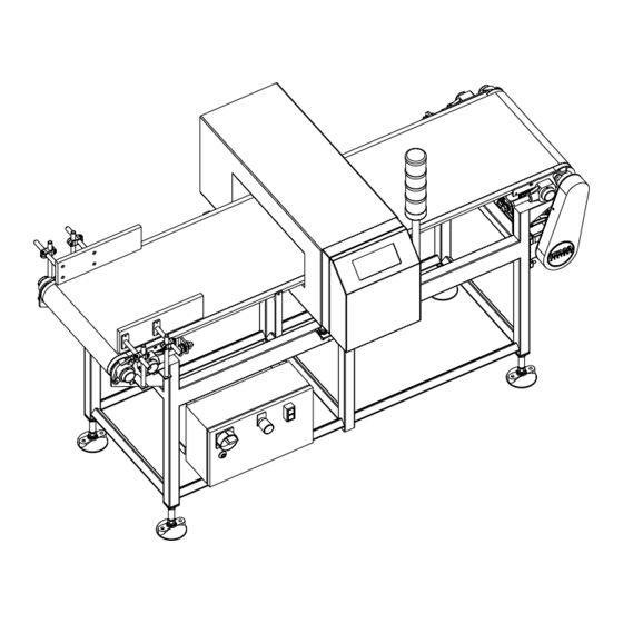
About the metal detector range Freefall versions This section describes Loma Freefall Metal Detectors, designed to detect ferrous and non- ferrous contaminants in products fed by gravity through some form of hopper and pipework into a packaging system. Short and long frame models The following illustration shows the surface mount short and long frame models: NOTE: The detector fitted depends on the model requirements. - Page 38 About the metal detector range The unit can be free standing or suspended from overhead fixings depending upon the application. The unit consists of a search head and controls, with an auxiliary electrical enclosure mounted on a reject diverter system. A circular product pipe is supplied for connection to the existing product pipework via a flexible gaiter.
- Page 39 About the metal detector range The following illustration shows a typical slimline model: MULTIHEAD PIVOT MOUNT HOPPER REDUCING CONE CONTAINED FIELD (CF) FREEFALL METAL DETECTOR Catalogue contained field model Like the slimline version, the detector is of a contained field design to minimize the metal free area requirement.
- Page 40 About the metal detector range The following illustration shows a typical catalogue model: 4 HOLES TAP M8 THROUGH SEARCH HEAD 2 HOLES IN EACH SIDE DIA. 9.0 APERTURE Mounting arrangements Like all metal detectors, a Freefall Metal Detector performs better when it is free from vibration.
- Page 41 About the metal detector range Anti-vibration mounts are recommended for use only where the level of vibration is significant and there is no metal in the metal-free area. Mounting on a Tufnol plate is often more appropriate. This provides a rigid fixing and is non-conductive. Pivot mounting simplifies the changeover of product and also cleaning of the detector.
- Page 42 About the metal detector range Voltage free reject contact rating (Stand alone 5A @ 250V ac or 3A @ 30V dc resistive load model) 2A @ 250V ac or 2A @ 30V dc inductive load 5091...
- Page 43 About the metal detector range 5091...
-
Page 44: Using The Metal Detector
Using the metal detector This chapter provides general information about using the metal detector, including a simple discussion of the principles of operation to explain how it works. It also describes the general procedures for entering a keycode, moving between the menus, adjusting parameters, and adjusting the sensitivity. -
Page 45: Principles Of Operation
Using the metal detector Principles of operation Before using the metal detector it is helpful to understand its principle of operation, as this will help you understand the measurements it makes and the basis it uses for detecting a metal contaminant in a foodstuff. Although several different types of metal detector are produced, to suit different types of foodstuff, they all operate in essentially the same way. -
Page 46: Getting The Best Results
Using the metal detector When there is nothing between the coils the voltage in each receiver coil will be identical, because they are an equal distance from the transmitter coil, and the signal is zero. Any conductive object moving between the coils will interact with the magnetic field to produce a voltage difference between each of the receiver coils. - Page 47 Using the metal detector Relative detectability of non-ferrous metals The resistance, and hence ease of detection, of different non-ferrous metals varier widely. The more conductive they are, the easier they are to detect, as shown in the following graph: Sensitivity to stainless steels is invariably poorer than to other non-ferrous contamination. This is largely due to the relative conductivity of the material as shown above.
-
Page 48: Good Practice
Using the metal detector Good practice The following procedures are recommended for ensuring and maintaining an effective metal inspection regime. There are three essential components in using the IQ Metal Detector effectively: • Establishing detector sensitivities • Regular in-line detector sensitivity testing •... - Page 49 Using the metal detector Regular in-line detector sensitivity testing It is important to maintain regular and accurate in-line sensitivity testing of the metal detector using the same techniques as the initial sensitivity testing. This should include tests to ensure that the reject systems are effective. Regular testing should be conducted using the same techniques as initial sensitivity testing.
-
Page 50: Iso9000
A certificate of calibration would then be issued for that piece of equipment. Loma recommend this calibration should be done at least yearly. -
Page 51: Entering A Keycode
Using the metal detector Entering a keycode The metal detector can be set up to restrict access using a keycode. When the key panel is locked pressing any key apart from will prompt for the keycode. To enter a keycode •... -
Page 52: The Displays
Using the metal detector The displays During normal operation you can step between the following displays using Threshold/signal display T*1000 Shows the signal, together with the threshold above which packs will be rejected. The signal is updated continuously as the signal changes. Bargraph display ™™™™™™... -
Page 53: Control Panel
Using the metal detector Control panel Operator keys The following table explains the function of the control panels keys: Description Cancel key – Cancels the current operation. Lock key – Locks the keyboard. Arrow keys – Allow you to step between menu options or change the value of the current menu option. -
Page 54: Adjusting The Sensitivity/Threshold
Using the metal detector Adjusting the sensitivity/threshold The threshold determines the signal above which packs will be rejected. For example, with no product passing through the metal detector the signal might be between 0 and 10, and with uncontaminated product the signal might be between 50 and 200. In this case you could set the threshold to 300 to cause all packs giving a signal of 300 or greater to be rejected. -
Page 55: Using The Menus
Using the metal detector Using the menus The options for setting up, calibrating, and checking the operation of the metal detector are accessed from the four menus which you can select using the , or keys. To select a menu •... - Page 56 Using the metal detector To edit a text field • Press to edit the text. Name The previous text will be displayed; blanks will be displayed if there was no previous text. • Press to step Name between the following characters: Underline, Space, 0 to 9, and A to Z.
- Page 57 Using the metal detector 7031...
-
Page 58: Setting Up A New Product
Setting up a new product This chapter explains how to create a new product code and calibrate the metal detector for that product. It also contains the Quick Setup Guide. A tear-out laminated copy of which can also be found at the back of this user guide. -
Page 59: Setting Up A Product
Setting up a new product Setting up a product The metal detector must be calibrated for each of the different types of product it will be used with. Each time you use the metal detector you must specify which product you are testing to ensure it is running with the correct calibration. - Page 60 Setting up a new product (Continued) To set up a new product • Press to edit the name. *Name CHOCOLATES • Enter a name of up to 10 characters and press to confirm it. For information about editing the name see To edit a text field, page to display the Frequency •...
- Page 61 Setting up a new product (Continued) To set up a new product to display the Flow • Press *Flow length 255 mm length option. This option allows you to enter the length of the pack to flow allowing for any skew. to display the Rej delay •...
- Page 62 Setting up a new product (Continued) To set up a new product • Press to move to the next entry. Full calibrate ? The display will show Full calibrate? or Reverse calibrate? if the Detection option is set to REVERSE in the Product setup menu.
-
Page 63: Quick Setup Guide
Setting up a new product Quick Setup Guide 7031... - Page 64 Setting up a new product To adjust the sensitivity To set up a new product • If necessary use C to move to the • Press s. top level of the menus. • Press e twice. • Select either the bargraph or •...
- Page 65 Setting up a new product 7031...
-
Page 66: Displaying And Printing Reports
Displaying and printing reports This chapter gives information displaying the batch results, and the contaminant, error, and fault reports, using the options on the Results menu. It will also describe how to produce printed reports, using the settings on the Reports Option submenu of the Setup menu. -
Page 67: Displaying Batch Results
Displaying and printing reports Displaying batch results The metal detector maintains the following statistics for the current product: Statistic Description Product The product name Reject count The number of products rejected Accept count The number of products accepted Note that this will only be displayed when a photo-eye is used for product registration. -
Page 68: Producing Reports
Displaying and printing reports The batch is reset automatically whenever the product is changed or when a batch report is generated. Producing reports The metal detector can produce a range of reports about product statistics, machine calibration information, and machine status information. These can either be printed to a printer attached to a unit or transmitted down the serial link to a PC or Network. - Page 69 Displaying and printing reports A sample report is shown below: --------------------------------------- LOMA IQ METAL DETECTOR --------------------------------------- BATCH REPORT Time : 15-37-02 Date : WED 20 SEP 1995 Machine Identification : LINE 12 Product number : Product Identification : CHOCOLATES Number of packs passed :...
- Page 70 Displaying and printing reports To specify which report to produce (Continued) until the Report options • Press Report options menu is displayed and press select it. If this option does not appear on the Setup menu check that you have turned on the link in the Serial Link submenu of the Service menu.
- Page 71 Displaying and printing reports To specify the batch statistics (Continued) to display the Batch • Press *Batch units TIME units option. • Select TIME for the batch interval to The Batch interval can only be specified in be specified by time, or PACK for the terms of the number of packs if a photo-eye is fitted;...
-
Page 72: Displaying The Contaminants, Run Errors, And System Faults Logs
Displaying and printing reports Displaying the contaminants, run errors, and system faults logs The IQ Metal Detector maintains the following logs containing information about the product being tested: Contaminants log This contains details of the date and time of any contamination, as well as the product signal recorded for the contaminated product. - Page 73 Displaying and printing reports To view the log entries until the appropriate View • Press View errors option is displayed: • Press to select it. + Log empty + If there are no entries in the log the message Log empty will be displayed.
- Page 74 Displaying and printing reports To print a copy of the log • Select the log you want to print from Error report ? the Results menu. • Press to display the appropriate Report option. • Press to select it. + Report sent + The display will show Report sent.
- Page 75 Displaying and printing reports 7031...
-
Page 76: Setting Up The Metal Detector
Setting up the metal detector This chapter explains how to calibrate the metal detector and set up the parameters affecting the operation of the machine. Real-time clock and PV test are only available with the optional reports/logs package. -
Page 77: Calibrating The Metal Detector
Setting up the metal detector Calibrating the metal detector The metal detector provides three alternative calibration procedures: Update calibration fine-tunes the compensation value to minimize the signal, while still checking for metal in the product. Use an update calibration to update the signal when the production line is running, if false rejects are occurring because the signal has drifted. - Page 78 If in doubt, call your nearest Loma Service Centre. 8024...
- Page 79 (eg. for frozen product, the calibrate pack must be frozen). If in doubt, call your nearest Loma Service Centre. +Power reducing+ The unit is reducing the head power to account for the product effect of the product.
-
Page 80: Setting Up The Calibration Parameters Manually
, and then press Manual setup twice until the display shows Manual setup. to select Manual setup. • Press The options on the Manual Setup menu are normally set up by a Loma Service engineer and should not normally be adjusted. 8024... -
Page 81: Setting The Working Mode
Setting up the metal detector Setting the working mode The metal detector operates in one of three alternative modes to give the best results with different types of product. DRY mode is used for products with no product effect. RESIST mode is used for products that exhibit some product effect, such as cocoa, iron fortified cereals, flour, etc, or that contain some moisture. -
Page 82: Setting The Trigger Thresholds
Setting up the metal detector Setting the trigger thresholds The calibration procedure automatically determines the best threshold setting based on the samples pack used for calibration. Manual setup allows you to specify the minimum and maximum values for the threshold, as a safeguard that the calibration has been performed correctly. -
Page 83: Adjusting The Threshold And Compensation
Setting up the metal detector To set the trigger threshold • Press to display the current *Trig thresh 1000 trigger threshold and press edit it. This option will only appear if the Calib trigger option has been set to On in the User Options menu. •... - Page 84 Setting up the metal detector (Continued) To adjust the threshold • Press to edit the threshold. • Press keys to increase or decrease the threshold The threshold can be adjusted between 0 respectively and press and 65535, in steps of 5, and defaults to confirm it.
-
Page 85: Adjusting The Head Power
Setting up the metal detector Adjusting the head power The head power is set automatically during full calibration and should not normally need adjustment. However, you have the option of adjusting the head power manually, and locking the adjustment so that it will not be changed during calibration. To adjust the head power •... -
Page 86: Setting The Time And Date
Setting up the metal detector Setting the time and date It is important that the correct time and date are set on the machine as they are used to time stamp the data in the contaminant, fault, and error logs, and are shown on the printed reports. -
Page 87: Setting The Machine Id
Setting up the metal detector Setting the machine ID The Machine details menu provides information about the software fitted to the metal detector and the machine ID. The machine ID is printed out on any reports and can be edited to any convenient number, such as the identifier used in the factory. - Page 88 Setting up the metal detector To lock the keyboard • Press Lock keyboard ? The following prompt is displayed: • Press to lock the keyboard. + Keyboard locked + Keyboard locked will be displayed: Access will now be restricted to entering the numbers specified in the keycode change and PV test options.
- Page 89 Setting up the metal detector 8024...
-
Page 90: Using Performance Validation
Using Performance Validation This chapter explains the benefits of the Performance Validation procedure, and explains how to set up the metal detector for PV testing, with information about each of the parameters that need to be specified. -
Page 91: Introduction
At the end of the Performance Validation test the results are transmitted to a PC or printer to produce a printed copy of the report. A typical PV Test report is shown below: --------------------------------------- LOMA IQ METAL DETECTOR --------------------------------------- PV TEST REPORT... -
Page 92: Setting Up Pv Testing
Using Performance Validation Setting up PV testing To use PV testing the PV Test option must be set to YES in the User Options menu. An additional PV test setup option will then appear when defining a new product: PV test setup •... - Page 93 Using Performance Validation To set the performance validation interval (Continued) to display the Synch • Press *Synch 14.30 option and press to edit it. Set Synch to 00.00 for unsynchronized • Press to increase or testing. For example, if the Interval is set to decrease the synch time respectively six hours each PV test will be initiated six and press...
- Page 94 Using Performance Validation The following options in the PV test setup menu allow you to specify the types of test that should be performed during performance validation. The test wands you specify for performance validation should have been determined using sensitivity tests with the product after calibration To specify the characteristics of the PV test...
-
Page 95: Running A Performance Validation Test
Using Performance Validation To specify the false threshold to display the False • Press *False thresh 2000 thresh option and press to edit It can be set to any value between 0 and This is used to identify metal test 99990, and can be adjusted in steps of ten samples or other metal objects that units. - Page 96 Using Performance Validation To run a performance validation test to display the Results • Press Run PV test menu. arrow until the Run PV • Press test option is displayed. • Press to confirm that you want to run the PV test. The following Operator prompt will *Operator id be displayed:...
- Page 97 Using Performance Validation To cancel a performance validation test • Press If the PV test was run manually no error is caused, but if the PV test was initiated automatically a non-action error is recorded and a report is generated. At the end of the PV test the display will revert to the previous display.
-
Page 98: Installing The Metal Detector
Installing the metal detector This chapter describes how to install the metal detector range. It first gives general information, applicable to all versions, followed by specific installation instructions for each version. -
Page 99: General Information
Installing the metal detector General information The following information applies to all versions of the metal detector. For a description of each version of the metal detector range see the chapter About the metal detector range, page 1. Warnings The following safety warnings apply to the procedures for all versions: 1. - Page 100 • Remove and discard all packing and protective materials. EMC considerations All Loma equipment is designed to operate under factory conditions, and has been tested to recognised international standards for Electromagnetic Compatibility (EMC). It is still necessary, however, to ensure that the equipment is not subjected to excessive electrical noise via its supply or airborne sources.
- Page 101 Installing the metal detector The input voltage should not be subject to voltage fluctuations outside the limits (NWML0320): • Minus 15% to plus 10% of the nominal supply voltage (230V or 110V). • Zero voltage for more than 20mS. • 50% of nominal voltage for more than 40mS. •...
- Page 102 F1 (T2A) Loma part number 517033 located in the incoming ac supply circuit, F2 and F3 (T5A) Loma part number 517026 located in the reject relay circuits. All the fuses can be found beneath the power supply safety mesh cover.
- Page 103 Installing the metal detector WARNING: For continued protection against the risk of fire replace only with the same type and rating of fuse. Access to the fuses can be gained as follows: • Using the 5mm allen key supplied with your equipment, unscrew the two front hinged door screws on the control box and open the door.
-
Page 104: European Belt Conveyor Versions
European belt conveyor versions This section describes how to install Loma flat belt and plastic modular belt conveyors that are ready fitted with Loma metal detector search heads. After connection of the appropriate services, a conveyor is ready for immediate use. - Page 105 Installing the metal detector piece of machinery as this could lead to vibration being transmitted to the head, resulting in spurious triggering. • When the height is correct, lock the wheels (if fitted). • If the conveyor is fitted with feet, you are recommended to apply silicone sealant around the feet and floor.
- Page 106 Installing the metal detector • Make the connections to the isolator switch as follows: 3-phase earth and neutral Core Terminal 3-phases L1, L2 & L3 Neutral Earth 3-phase earth and neutral Core Terminal 3-phases L1, L2 & L3 Neutral Not used Earth 3-phase earth and neutral Core...
- Page 107 Installing the metal detector The following illustration shows a typical regulator unit: PRESSURE ADUSTER PRESSURE GAUGE INCOMING AIR SUPPLY 90° ELBOW FITTING WATER TRAP DRAIN With the exception of conveyors fitted with either an air-blast reject system or Stop-On-Detect reject, a low-pressure air switch is fitted electrically in series with the starter motor coil.
- Page 108 Installing the metal detector • At the electrical services box, press the ‘Start’ button. Check that the conveyor starts and the belt runs in the correct direction. If it is running correctly: • Where a low air pressure switch is fitted, disconnect the air and check that the motor stops.
-
Page 109: Pipeline Versions
Installing the metal detector Pipeline versions This section describes how to install a Loma stand-mounted pipeline metal detector. After connection of the appropriate services, the detector is ready for immediate use. Warnings The following additional safety warnings apply to these procedures: 15.SECURITY WHEN STAND MOUNTED... - Page 110 Installing the metal detector Connecting electrical supplies Pipeline detectors require a single-phase electrical supply. Electrical connections are made to a connector block inside the control box. The following illustration shows the connection arrangements at the connector block: JP301 TP303 Live Neutral The main incoming earth connection is made to the left-hand control box ground stud (in a group of 3)
- Page 111 Installing the metal detector • Refer to the previous illustration for connector block wiring details. Make the connections to the connector block as follows: AC wiring colours will vary according to territory. North America Black UL approved models White NEUTRAL 120V Green/Yellow EARTH...
-
Page 112: Handtmann Versions
• Set up the unit as described in Setting up the metal detector, page 59. Handtmann versions This section describes how to install a Loma Handtmann metal detector. The detector is mounted from the hinge block located on the filler outfeed adjacent to the filler product pipe. - Page 113 Installing the metal detector Handlinking applications This requires the removal of the hand linking gearbox assembly from the filler hinge and re- fitting it to the replica hinge block on the outfeed of the metal detector assembly. Power and reject connections are made as follows: If the metal detector does not have a fitted power cable, power is connected as described in Connecting electrical supplies, page 93.
- Page 114 Installing the metal detector AL applications This requires the uncoupling of the AL machine from the filler hinge block and re-coupling it to the replica hinge block on the outfeed of the metal detector assembly. If the metal detector does not have a fitted power cable, power is connected as described in Connecting electrical supplies, page 93.
-
Page 115: Pharmaceutical Versions
Installing the metal detector Pharmaceutical versions This section describes how to install a Loma pharmaceutical metal detector. The detector is supplied complete with its own stand and reject mechanism. After connection of the appropriate services, the detector is ready for immediate use. -
Page 116: Freefall Versions (Stand-Alone)
• Set up the unit and verify the operation of the metal detector as described in Setting up the metal detector, page 59. Freefall versions (stand-alone) Loma supply two versions of stand-alone freefall metal detector search heads: • Catalogue contained field (CF) model. • Slimline contained field (CF) model. - Page 117 Installing the metal detector Catalogue units only • If mounted using the four holes located in the extension flange on the bottom of the detector case ensure that the framework to which it is secured is capable of supporting the weight of the unit. Slimline units only •...
- Page 118 Static precautions for dry powder products For products likely to generate static it is essential that the product pipe which runs through the aperture is fitted with an antistatic screen. Please consult your Loma Service Centre for details. Connecting electrical supplies The standard Loma stand-mounted freefall metal detector requires a single-phase electrical supply.
- Page 119 Installing the metal detector • Split the cable inside the box and cut the wires to suitable lengths. • Refer to the previous illustration for connector block wiring details. Make the connections to the connector block as follows: AC wiring colours will vary according to territory. North America Black UL approved models...
-
Page 120: Short And Long Frame Versions With Diverter Reject
Installing the metal detector Short and long frame versions with diverter reject These systems have a choice of mounting methods: surface standing on height adjustable feet or suspended from an overhead framework. General footprint drawings follow. The installation space required is dependent upon the detector aperture size. The space required can be determined from the measurement between the top of the infeed product pipe to the surface upon which it is to stand. - Page 121 Installing the metal detector When installing a short frame system attention must be paid to the metal free area requirements as set out in the Search head metal-free area, page 100. Metal free area long frame systems • There shall be no fixed metal closer to the detector aperture than 1.5 times the aperture size as measured from the centre line of the detector case depth.
- Page 122 Installing the metal detector Surface standing PLASTIC FEET GOOD/REJECT FLANGE DETAIL PNEUMATICS ACCESS DOOR REJECT GOOD REMOVABLE ACCESS PANEL DETECTOR AUXILIARY FOR CLEANING CONTROLS ELECTRICAL Fixings may vary ENCLOSURE Installation Footprint Floor Mount The system has ±75mm (3") of height adjustment via its screw legs. It is advisable to keep the amount of extended leg as short as possible.
- Page 123 Installing the metal detector Suspension mount 4 MOUNTING HOLES TO SUIT M16 STUDDING GOOD/REJECT FLANGE DETAIL PNEUMATICS ACCESS DOOR REJECT GOOD REMOVABLE ACCESS PANEL DETECTOR AUXILIARY FOR CLEANING CONTROLS ELECTRICAL Fixings may vary ENCLOSURE Installation Footprint Suspension Mount The system should be hung rigidly using 16mm studding insulated from the main framework; it must be level across the corners.
- Page 124 Installing the metal detector Connecting the air supply NOTE: An air supply at a pressure of between 3.5 bar (52psi) and 4.5 bar (66psi) is required to operated the reject device. The air supply must be dry and lubricated. • Connect the compressed air supply to the input side of the air regulator unit via 10mm outside diameter pipe.
- Page 125 Installing the metal detector Connecting the electrical supply The system requires a single-phase ac supply with earth and neutral as indicated by the voltage label on the enclosure. The supply is connected via the main isolator located on the right-hand side of the control box when facing the detector controls.
- Page 126 Installing the metal detector • Make the connections to the connector block as follows: LIVE NEUTRAL GROUND CONNECTORS CONDUITTO INPUT ENCLOSURE CABLE AC wiring colours will vary according to territory. North America Black UL approved models White NEUTRAL 120V Green/Yellow EARTH Brass terminal All Others...
-
Page 127: Iq2 Search Head Only Installation
Installing the metal detector search head only installation This section describes how to install a Loma metal detector search head to either an existing conveyor or to a conveyor being built by a customer. Electrical supply considerations All Loma equipment is designed to operate under factory conditions, and has been tested to recognised international standards for mains-borne interference. - Page 128 Installing the metal detector The following illustration shows the connection arrangements at the connector block: JP301 TP303 Live Neutral The main incoming earth connection is made to the left-hand control box ground stud (in a group of 3) located just below the right-hand edge of the control board.
-
Page 129: Mounting Heads On Conveyors
There are a number of points to watch when fitting a new Loma Metal Detector head to an existing conveyor of whatever manufacture, or when building a new conveyor to incorporate a metal detector head, if nuisance triggering necessitating operation at reduced sensitivity settings is to be avoided. - Page 130 Installing the metal detector • The belt must be supported through the aperture by a non-metallic skid plate such as Tufnol which must be strong enough not to bow under the product weight. • Electrical Interference. The reject relay usually switches inductive loads such as motor starter contactors, solenoid valves etc.
- Page 131 Installing the metal detector With rollers it is virtually impossible to provide a constant resistance path, mainly because the bearings are usually lubricated by grease which is non-conductive. The balls act as the contacts and in consequence the contact resistance varies as they move through the grease. Here the alternative approach of permanently open circuiting the loop must be taken by electrically insulating one end of the roller shaft from the frame of the conveyor.
- Page 132 Installing the metal detector into the aperture must also be non metallic. Use Darvic or some similar material and keep the mounting posts out of the metal free area. Moving metal Moving metal must be sited at least three times the smaller of the two aperture dimensions from the centre of the head, as illustrated in Further information, page 118.
- Page 133 Installing the metal detector Care must be taken when fitting a belt that all metallic swarf and filings have been cleared away and that all rollers are coated, preferably with PVC, to prevent rust formation. Rust on the rollers or swarf will be picked up onto the underside of the belt and will cause false triggering.
- Page 134 Installing the metal detector paging aerials and loops, RF heaters, welders of all types and even airport radar. The only cure is to re-orientate either detector head or the source of interference so that the aperture is not looking directly at it. Post-installation problems Commissioning procedures are covered comprehensively in Service Bulletin MD20.
- Page 135 Installing the metal detector Further information This section contains standard mounting positions for Loma Metal Detector heads. 9094...
- Page 136 Installing the metal detector Further information and advice can always be obtained from the Service Department. 9094...
- Page 137 Installing the metal detector 9094...
-
Page 138: Maintenance
Maintenance This chapter describes the maintenance procedures for the metal detector range. -
Page 139: Inspection And Cleaning Procedures
Maintenance Inspection and cleaning procedures These procedures relate to all the metal detectors in the IQ range unless otherwise specified. Invalidation of Warranty Your warranty may be invalidated if you do not follow the maintenance schedule set out within this user manual. This warranty statement is in addition to the terms of sale. - Page 140 Maintenance Do not hose wash UL approved controls; use only a light hand wash and wipe dry procedure. Cleaning regime A typical cleaning regime consists of the 5 stages. • Pre-rinse • Detergent rise • Rinse • Disinfectant rinse • Final rinse Cleaning solutions Detergents are typically alkaline solutions with a PH value of 5 to 6.
- Page 141 Maintenance • If fitted remove the reject container. Empty and wash with mild detergent. • Brush any loose debris off the exposed conveyor surfaces and belt scraper if fitted. • Wash conveyor, detector aperture, rollers, skid plate and underside of belt using mild detergent.
-
Page 142: Specific Cleaning Procedures
NOTE: After any of the following procedures thoroughly dry all the washed components to remove any detergents, to avoid product contamination. Cleaning the automatic reject valve (Loma ARV) • Isolate the electrical and compressed air power supplies to the metal detector. - Page 143 Maintenance • Turn the handles in a clockwise direction to secure the piston assembly in the body. • Tighten the two locking screws. • Restore the electrical and compressed air power supplies to the metal detector. NOTE: Do not inject water directly into Linker drive gears. 10087...
- Page 144 Maintenance Cleaning the product pipe and couplings Pipeline versions • If the product pipe is fitted with a water jacket isolate the water supply and disconnect the water pipes. • For 2", 3" and 4" models undo the product pipe from the fixed fitting using the spanner provided.
- Page 145 Maintenance O RING SEAL ACTUATOR FLOW DIVERT VALVE PISTON ASSEMBLY DIVERT VALVE REJECT • Check that the fitted ‘O’-rings and the split bushing are in good condition. Replace as necessary. • Screw the piston onto the actuator. • Replace the lower valve body and clamp the upper and lower valve bodies together. Replacing the actuator bushing/packing Pipeline versions •...
- Page 146 Maintenance • Apply 60psi air to the end cap, which will force the packing and bushing out. Remove the air supply once this occurs. • Replace the packing (with the ‘v’ side facing the actuator) and the bushing, taking care not to damage or roll the lip of the packing.
- Page 147 Maintenance • Check that the fitted ‘O’-ring is in good condition. Replace as necessary. • Insert the “T” ball and seals into the valve body, and replace the valve stem, actuator coupling and adapter. • Replace the actuator bracket and tighten the four screws. •...
- Page 148 Maintenance • Unscrew fully both captive knurled screws that are attached to the reject support bracket. This releases the tray and flap. Hold the reject flap and pull the reject tray approximately 25mm away from the rotary solenoid. Disengage the reject flap from the shaft and remove it.
-
Page 149: Routine Maintenance
Maintenance Cleaning a diverter reject • Isolate the electrical and air supplies to the metal detector. • Release the swell latches or hand wheels (fixings may vary) on the removable access cover and carefully remove. The door is attached to the main frame by a ground lead and therefore cannot be completely removed. - Page 150 Maintenance Greasing Drive end and idle roller shafts on conveyor systems are fitted with bearings that require greasing at regular intervals. Freefall diverter reject devices are fitted with bearings that require greasing at regular intervals. Bearings should be greased four times per year, unless the environment or cleaning regime dictates greasing more frequently.
- Page 151 Maintenance Adjustment of the air pressure is normally carried out by pulling up the adjustment knob to release the lock and by turning the control clock or anticlockwise the pressure can be adjusted. Removal of water from the water trap bottle is carried out by operation of a rotating knob or by pressing a button.
- Page 152 Maintenance • Carefully slide out the plastic hinge pins and remove the section of belt to be replaced. • Carefully interlock the new section of the belt. Make sure the belt is located on the drive sprocket and correctly engage with the other ‘floating’ sprockets. •...
- Page 153 Maintenance 10087...
-
Page 154: Appendices
Appendices... -
Page 155: Appendix A - Reverse Calibration
Appendices 11050... - Page 156 Check that the correct calibrate pack(s) is representative of production packs. If in doubt, call your nearest Loma Service Centre. +Power reducing+ The unit is reducing the head power to account for the metal content of the product.
-
Page 157: Appendix B - Commissioning Guide
Wherever possible this will be carried out by Loma before the unit is dispatched, or by a Loma Service Engineer during a commissioning visit. Primarily, this information is required to optimise machine performance for the application, and to enable certain features. - Page 158 Appendices The parameters and available options are summarised in the following table: Parameter Options Language ENGLISH (default entry), FRANÇAIS, NEDERL, DEUTSCH, ESPAÑOL, ITALIAN, PORTUGES, KATAKANA. Type CONVEYOR, FREEFALL, PIPELINE or PHARM. Units METRIC or IMPERIAL. Select YES if a photo-eye has been wired to the control board. Photo-eye Select YES if a blocked or disconnected photo eye is to cause a System PEC fault...
- Page 159 Appendices NOTE: PEC is the abbreviation for Photo-electric cell (photo eye). PEC fault is only available from software version IQ2V1.6.0. The following table summarises the available tolerance settings: Menu position % of calibrated threshold added 100% The Auto-calibration periods are summarised in the following table: Photo-eye No photo-eye Short...
- Page 160 Appendices The available options are summarised in the following table: Options Description Tracker This option will only appear if phot-eye operation has been selected in the Configuration menu. Turn this ON or OFF as required. Leave this at the default option of ON to enable access to the reject timing Reject time information in the Product setup menu.
- Page 161 Appendices To set up serial links If you are using any of the serial links, then you will need to set up the serial links as follows: Serial link menu configuration Link 1 may be set to one of the following options. Press to select the usage list then press it again and use to select one of the uses below:...
- Page 162 On systems employing variable speed conveyors, special hardware is required to drive the CTB (conveyor time base) input on the micro control card. Conveyor systems supplied by Loma will already have this hardware fitted and commissioned, but on head only sales the following information should be observed when using vari-speed.
- Page 163 Appendices accurate rejection, but not so much that the CTB rate will exceed a frequency of 100Hz at the maximum belt speed. An absolute minimum of 4 pulses must occur over the coil gap distance. The coil gap distance can be found on the machine details plate (inside control box).
-
Page 164: Appendix C - Product Signal Tracking Menu
Appendices Appendix C – Product signal tracking menu This facility allows the detector to automatically adjust the working threshold between two pre-set limits to enable the sensitivity of the detector to be optimised in situations where the product signal drifts up and down with the change in product effect. For instance, for a frozen product the product effect is very small when the product has just come out of the freezer allowing a low working threshold level to be used giving a high sensitivity to metal contaminants. - Page 165 Appendices Upon completion of the product calibration routine the derived working threshold will be used unless the product signal initiates a change. The following table describes the options on the Tracking menu: Menu Description Advice *Tracking Turns the tracker Can be set on a per product basis. option on or off.
-
Page 166: Appendix D - Service Menu
Appendices Appendix D – Service menu The entries within this menu allow certain user options and facilities to be turned on and off, as appropriate to your machine application. These options are detailed in the following table: Options Description Tracker Allows the user to select the tracker option for each of the products as required. - Page 167 NORMAL or REVERSE mode for the product selected. Wherever possible, Loma will have set the entries within this menu to those required by your application before the dispatch of your system, or during a commissioning visit by a Loma engineer if applicable.
-
Page 168: Appendix E - Reject Options
Appendices Appendix E – Reject options The entries contained within this menu allow selection of the type of reject timing and certain reject options as described below. Mode Selects the reject configuration from the following options: Pulse (only available if a photo-eye is fitted) When a contaminated package is detected the reject delay time is counted down, in order for the package to travel from the photo-eye to the reject device, where-upon the reject is turned on for a time equal to the reject dwell time. - Page 169 Appendices 11050...
-
Page 170: Appendix F - Wiring Diagram For External Sensors
Appendices Appendix F – Wiring diagram for external sensors 11050... - Page 171 Appendices 11050...
-
Page 172: End-User License Agreement
2. Rights and Limitations: The software is licensed as a component within the IQ2 Metal Detector only, and may not be separated for use elsewhere. The software is licensed with the IQ2 Metal Detector as a single integrated product. The software may only be used with the IQ2 Metal Detector. - Page 173 License agreement...
-
Page 174: Index
Handtmann versions contacting Loma pharmaceutical versions Contaminants log pipeline versions control unit search head only conventions short and long frame versions 103 Currently selected product... - Page 175 Index product codes, selecting Product setup menu logs Product signal tracking menu clearing PV Test setup menu Contaminants log PV testing displaying running a test Errors log setting the interval Faults log setting up printing specifying the characteristics 77 Machine details menu quality assurance viii manual setup...
- Page 176 Index sensitivity, adjusting Service menu text field, editing setting machine ID Threshold signal display setting time and date thresholds setting up manually adjusting setting up products setting minimum and statistics maximum accept count setting the trigger threshold product reject count specifying User Options menus total count...
- Page 177 Index...
Need help?
Do you have a question about the IQ2 and is the answer not in the manual?
Questions and answers