
Related Manuals for NCR 7167


Summary of Contents for NCR 7167
- Page 1 NCR 7167 Two Station POS Printer Release 1.0 Owner's Manual B005-000-1406 Revision C November, 2002...
- Page 2 NCR, therefore, reserves the right to change specifications without prior notice. All features, functions, and operations described herein may not be marketed by NCR in all parts of the world. In some instances, photographs are of equipment prototypes. Therefore, before using this document, consult with your NCR representative or NCR office for information that is applicable and current.
- Page 3 EACH end of the cable. Use of a cable other than described here will require that you test this cable with the NCR printer and your system for FCC and CE mark certification.
- Page 4 This equipment must be installed and used in strict accordance with the manufacturer's instructions. However, there is no guarantee that interference to radio communications will not occur in a particular commercial installation. If this equipment does cause interference, which can be determined by turning the equipment off and on, the user is encouraged to contact NCR immediately.
-
Page 5: Quick Reference
Quick Reference This Quick Reference will direct you to key areas of the Service Manual. For a complete listing of topics, consult the Table of Contents or the Index. Setting Up the Printer ............ page 9 Basic requirements for unpacking and installation, connecting the printer, turning it on, and running the print test. -
Page 6: Who Should Use This Book
The service guide is intended as a guide for service representatives, field engineers, and those who will be installing and learning about the 7167 printer. It can also be used as a reference for service courses. -
Page 7: Table Of Contents
Who Should Use this Book? ................vi How to Obtain More Information ..............vi Revision Record ......................vi Contents ........................vii Chapter 1: About the 7167 Printer Features and Options ....................1 Receipt Station...................... 2 Slip Station......................2 Receipt and Slip Print Stations................3 General Features .................... -
Page 8: Contents
7167 Owner’s Manual Contents Serial Port Configuration Methods ..............37 Uninstalling the Drivers ................... 37 Using the Printer ....................... 39 Loading and Changing the Receipt Paper............. 40 Removing the Paper Roll .................. 41 Loading the Paper Roll ..................42 Advancing Paper ....................43 Installing and Changing the Ribbon Cassette............ - Page 9 7167 Owner’s Manual Contents RS-232C 9-Pin to 9-Pin Cable Diagram............75 USB Cable Connector ..................76 Power Cable Connector ..................76 Cash Drawer Connector and Pin Assignments ..........77 Setting Extra RS-232C Options ................ 78 Chapter 6: Commands Introduction....................... 73 List of Commands and Location................
- Page 10 7167 Owner’s Manual Contents Dimensions and Weight..................215 Density of Receipt Print Lines................215 Duty Cycle Restrictions (Printing Solid Blocks) ..........215 Appendix B: Print Characteristics Character Size......................217 Receipt Station....................217 Slip Station......................218 Print Zones....................... 221 Receipt Station....................221 Slip Station......................
-
Page 11: Chapter 1: About The 7167 Printer
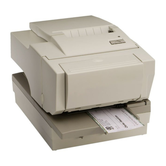
Extended Slip Table The 7167 printer is a fast, quiet, relatively small and very reliable multiple- function printer. It prints receipts, validates and prints checks, and prints on a variety of single- or multiple-part forms. There is no journal as it is kept electronically by the host computer. -
Page 12: Receipt Station
7167 Owner’s Manual Chapter 1: About the 7167 Printer Receipt Station Thermal printing Standard pitch (host selectable): 15.2 characters per inch, 44 columns Compressed pitch (host selectable): 19.0 characters per inch, 56 columns Resident bar codes • Code 39 •... -
Page 13: Receipt And Slip Print Stations
One cash drawer connector (supports 2 cash drawers) History EEROM for custom settings Audible tone (controlled by application) Note: The 7167 does not have a paper journal. The journal is kept electronically by the host computer. Options Magnetic Ink Character Recognition (MICR) check reader built into the slip station for verifying... -
Page 14: Thermal Print Head
Chapter 1: About the 7167 Printer Thermal Print Head The 7167 Receipt Station uses a thermal print head for printing receipts, and is extremely fast and quiet. Since it uses heat to print directly on paper, there is no cassette or ribbon to change, eliminating soiled fingers and paper dust. -
Page 15: Ordering Paper And Supplies
Thermal receipt paper, ribbon cassettes, and forms can be ordered. Documentation is also available. Ordering Thermal Receipt Paper The 7167 requires NCR qualified thermal paper to be used on the thermal receipt print station to insure proper operation of the printer. In addition the paper rolls must be have the following dimension. -
Page 16: Ordering Ribbon Cassettes
7167 Owner’s Manual Chapter 1: About the 7167 Printer Ordering Forms The 7167 prints on single- or multiple-part forms in the slip station (up to five-part forms). Forms and slips must meet the following requirements: Front insertion (minimum): 51 mm (2.0 inches) wide 70 mm (2.75 inches) long... -
Page 17: Ordering Other Supplies
7167 Owner’s Manual Chapter 1: About the 7167 Printer Ordering Other Supplies Contact your NCR sales representative to order the supplies listed in the table. Item Type Number Power supply with attached cable to 75 Watt Power Supply 7167-K331-V001 printer and U.S. power supply cord... -
Page 18: Cleaning The Printer
Cooking oils Ultraviolet light There is no scheduled maintenance required for the 7167. Clean the cabinet as needed to remove dust and finger marks. Use any household cleaner designed for plastics, but test it first on a small unseen area. If the receipt bucket is dirty, wipe it with a clean, damp cloth. -
Page 19: Chapter 2: Setting Up And Using The Printer
Ribbon cassette • Thermal receipt paper roll Cardboard restraint for carriage (behind front cover) These items may be ordered as options from NCR and will be shipped separately: • Communication cable (from host computer to printer) • DC Power Cable •... -
Page 20: Removing The Packing Material
7167 Owner’s Manual Chapter 2: Setting Up and Using the Printer Removing the Packing Material Receipt Cover Head Gap Holder Carriage Holder 1. Remove the printer from the foam pack and plastic bag. 2. Open the front cover and remove the carriage holder. -
Page 21: Re Packing The Printer
Be prepared to answer questions concerning shipping and billing. Choosing a Location The 7167 printer takes up relatively little counter space and may be set on or near the host computer. Make sure there is enough room to open the receipt cover to change the paper and to open the front cover to change the ribbon cassette. -
Page 22: C) Wall Mounted Power Supply (Option)
7167 Owner’s Manual Chapter 2: Setting Up and Using the Printer 174 mm 6.85 in.) 316.20 mm (12.50 in.) 190 mm (7.50 in.) c) Wall mounted Power Supply (Option) The 75 watt power supply may be mounted on a vertical wall by using the holes on the cover. -
Page 23: Setting Switches
7167 Owner’s Manual Chapter 2: Setting Up and Using the Printer Setting Switches The DIP switches, located at the back of the printer, are used for three purposes: • To set variables for several printer functions (see the sections for the various printer functions in “Level 1 Diagnostics”... -
Page 24: Connecting The Cables
7167 Owner’s Manual Chapter 2: Setting Up and Using the Printer Switch 1 Settings Switch 2 Settings Printer State OFF (0) OFF (0) On-line Mode (default) ON (1) OFF (0) Diagnostic Mode OFF (0) ON (1) * Flash Download Mode... - Page 25 7167 Owner’s Manual Chapter 2: Setting Up and Using the Printer 6. For Host powered installation plug the DC cable into the POS terminal or plug the power cord into the power supply for remote power supply installation, then plug the power supply into an outlet.
- Page 26 7167 Owner’s Manual Chapter 2: Setting Up and Using the Printer Bottom of the Printer November 2002...
-
Page 27: About The Universal Serial Bus
Windows 98 (SR2), Windows 98 USB Hot Patch, ID: Q236934, NT 4.0 (Service Pack 3 or higher) and Windows 2000. Application developers need only redirect their software to the virtual serial ports created by the NCR USB solution to use the printer. November 2002... -
Page 28: Checking For Usb Support On The Host Computer
Windows 98 (SR 2), Windows 98 USB Hot Patch, ID: Q236934, NT 4.0 (Service Pack 3 or higher) and Windows 2000 natively support plug- and-play USB with a built-in driver; Windows NT does not, and the NCR windows NT USB driver needs to be installed. -
Page 29: Configuring The Printer
Configuring the Printer USB is a plug-and-play environment. As such, neither the printer nor the host requires user configuration to work. However, since the NCR solution simulates a serial communication interface, you must configure “handshaking” on the printer for proper operation. The printer can be configured to use hardware flow control (using DTR/DSR) or software flow control (using XON/XOFF). - Page 30 7167 Owner’s Manual Chapter 2: Setting Up and Using the Printer Back of Printer DIP Switch Bottom Cover Switch 2 is shown in the OFF position 4. Reset the printer. The printer beeps, prints the current configuration, then waits for you to make a selection from the Main Menu on the printout.
- Page 31 7167 Owner’s Manual Chapter 2: Setting Up and Using the Printer *** Diagnostics Form *** *** Printer Config Menu *** Model number 7167 The config menu allows you to set Serial number A991703053 general printer parameters. Sub-menus are entered and selections are made...
- Page 32 7167 Owner’s Manual Chapter 2: Setting Up and Using the Printer 6. Select RS232/USB. 7. Skip through the parameters with short clicks until Set Flow Control Method is displayed. 8. Follow the instructions to select either XON/OFF or DTR/DSR, then skip the remaining communications parameters.
-
Page 33: Installing The Usb Printer Drivers
7167 Owner’s Manual Chapter 2: Setting Up and Using the Printer Installing the USB Printer Drivers Windows NT users need to run Service Pak 3 or higher for a successful installation and should exit all Windows programs before starting. 1. Verify that the printer is plugged in and the power is on. - Page 34 7167 Owner’s Manual Chapter 2: Setting Up and Using the Printer November 2002...
- Page 35 7167 Owner’s Manual Chapter 2: Setting Up and Using the Printer Note: Location of the IONetworks files on the CD-ROM may very depending on the version of the CD that is being used. November 2002...
- Page 36 7167 Owner’s Manual Chapter 2: Setting Up and Using the Printer Also verify that you have the Windows 98 USB Hot Patch, ID: Q236934, created: 08- Jul-1999 and modified: 10Aug-1999 installed. To verify if this hot patch is installed check file c:\Windows\System32\Drivers\usbhub.sys. This file should be dated 08/13/99, size 36,672, version 4.10.22223.
- Page 37 7167 Owner’s Manual Chapter 2: Setting Up and Using the Printer Windows NT The printer beeps when it is plugged in to show the USB device is recognized. Click on the file you downloaded and follow the on-screen instructions. November 2002...
- Page 38 7167 Owner’s Manual Chapter 2: Setting Up and Using the Printer Windows 2000 Follow the on-screen instructions. The printer beeps when the USB device is recognized. Go to the location where you downloaded the drivers and double click the file.
- Page 39 7167 Owner’s Manual Chapter 2: Setting Up and Using the Printer November 2002...
- Page 40 7167 Owner’s Manual Chapter 2: Setting Up and Using the Printer Note: Location of the IONetworks files on the CD-ROM may very depending on the version of the CD that is being used. November 2002...
- Page 41 7167 Owner’s Manual Chapter 2: Setting Up and Using the Printer November 2002...
- Page 42 7167 Owner’s Manual Chapter 2: Setting Up and Using the Printer Note: Location of the IONetworks files on the CD-ROM may very depending on the version of the CD that is being used. November 2002...
-
Page 43: Checking The Installation
1. Open the Device Manager window, as you did in “Checking for USB Support.” 2. Scroll down to “Universal serial bus controllers.” The following devices should be displayed: • NCR 7167 Printer • NCR 7167 Serial Ports [Port#] (where the # is the location of the printer) November 2002... - Page 44 Chapter 2: Setting Up and Using the Printer 3. Scroll back up to “Ports.” You should see a COM number and port description for the NCR printer. If the devices are missing or are not listed correctly, the installation wasn’t successful.
- Page 45 7167 Owner’s Manual Chapter 2: Setting Up and Using the Printer Windows 2000: 1. Open the Device Manager window, as you did in “Checking for USB Support.” 2. Scroll down to “Universal serial bus controllers.” November 2002...
-
Page 46: Configuring Serial Port Number Assignments
Configuring Serial Port Number Assignments This section described how the NCR USB solution assigns serial port numbers (e.g., COMx) to the printer. The information that determines the assigned port number is stored in the host computer and not in the printer. This assignment is made in one of three ways. -
Page 47: Serial Port Configuration Methods
In many cases this is exactly what is desired. You can check the assigned serial port by clicking the General tab in the Edgeport utility. You’ll see an entry for the NCR printer. Expand the list to see which serial port has been assigned to the printer. - Page 48 1. Open the Device Manager and make sure “View Devices By Type” is selected. 2. Scroll down to Universal serial bus controller, and expand the list by pressing the “+” symbol. You’ll see two entries for your NCR printer. 3. Select the printer name and click Properties.
-
Page 49: Using The Printer
7167 Owner’s Manual Chapter 2: Setting Up and Using the Printer Using the Printer Paper Feed Button Note: See “Setting Switches” earlier in this book for instructions on setting the DIP switches. 1. Connect the power supply cable to the printer and turn on the power source. -
Page 50: Loading And Changing The Receipt Paper
7167 Owner’s Manual Chapter 2: Setting Up and Using the Printer Loading and Changing the Receipt Paper Although the illustrations show a used roll being removed, the instructions apply to loading paper for the first time. Change the paper when either of the following two conditions occurs: •... -
Page 51: Removing The Paper Roll
7167 Owner’s Manual Chapter 2: Setting Up and Using the Printer Removing the Paper Roll 1. Open the receipt cover. 2. Remove the used roll. Receipt cover November 2002... -
Page 52: Loading The Paper Roll
7167 Owner’s Manual Chapter 2: Setting Up and Using the Printer Loading the Paper Roll Note: Tear off the end of the new roll so that the edge is loose. 1. Place the new roll in the bin with a little extra paper extending over the front. -
Page 53: Advancing Paper
7167 Owner’s Manual Chapter 2: Setting Up and Using the Printer Advancing Paper 1. Press the Paper Feed button on the operator panel to advance the paper. The cover must be closed. To ensure print quality and the proper alignment of the paper, advance about 30 cm (12 inches) of paper. -
Page 54: Installing And Changing The Ribbon Cassette
7167 Owner’s Manual Chapter 2: Setting Up and Using the Printer Installing and Changing the Ribbon Cassette Change the ribbon cassette when the print is too light or the ribbon is frayed. Removing the Ribbon Cassette 1. Open the front cover. -
Page 55: Installing The Ribbon Cassette
7167 Owner’s Manual Chapter 2: Setting Up and Using the Printer Installing the Ribbon Cassette 1. Tighten the ribbon by turning the knob in the direction of the arrow. 2. Position the ribbon cassette slot at the catch on the printer slip frame and push it into place. -
Page 56: Printing On Forms Or Checks
Although the illustration on the facing page shows a check being inserted into the printer, the instructions apply to any type of form. The 7167 can print on forms up to five-parts thick. See “Ordering Forms” in chapter 1 for more information about the type of forms that can be used. - Page 57 7167 Owner’s Manual Chapter 2: Setting Up and Using the Printer Guide Extended Slip Table November 2002...
-
Page 58: Validating And Verifying Checks
7167 Owner’s Manual Chapter 2: Setting Up and Using the Printer Validating and Verifying Checks Note: If the MICR check reader feature is present, checks are verified then validated. 1. Insert the check from the front and place it on the slip table face down as shown in the illustration on the facing page. - Page 59 7167 Owner’s Manual Chapter 2: Setting Up and Using the Printer Guide Extended Slip Table November 2002...
-
Page 60: Chapter 3: Solving Problems
Chapter 3: Solving Problems Chapter 3: Solving Problems The 7167 printer is a simple, generally trouble-free printer, but from time to time minor problems may occur. For example, the power supply may be interrupted or the thermal print head may overheat. -
Page 61: Green Led Blinking (Slow)
7167 Owner’s Manual Chapter 3: Solving Problems Green LED Blinking (Slow) Problem What to Do Where to Go There are about 4 ½ meters, ± 3 meters, (15 Receipt paper is low* See “Loading and feet, ± 10 feet) of paper left. Change the paper Changing the Receipt Paper”... -
Page 62: Slip Or Forms Printing Is Light
7167 Owner’s Manual Chapter 3: Solving Problems AC supply voltage is out of If paper is not low and no conditions indicate range that the thermal print head is too hot, then it is likely that the power supply voltage is out of range. -
Page 63: Receipt Printing Is Light Or Spotty
7167 Owner’s Manual Chapter 3: Solving Problems Receipt Printing is Light or Spotty Problem What to Do Where to Go Thermal print head may be dirty Open the receipt cover and clean the thermal See “Cleaning the Printer” in chapter 2. -
Page 64: Micr Check Reader Not Reading Properly
7167 Owner’s Manual Chapter 3: Solving Problems MICR Check Reader Not Reading Properly Problem What to Do Where to Go MICR (Magnetic Ink Character Open the slip cover and clean the MICR read See “Adjusting the MICR Recognition) check reader does head with cotton swabs and isopropyl Check Reader”... -
Page 65: Other Serious Problems
For serious problems, such as the printer not printing, not communicating with the host computer, or not turning on, contact your NCR-authorized service organization to arrange for a service call. In addition to the service manual listed below, other service-related materials may be available. -
Page 66: Chapter 4: Diagnostics
7167 Owner’s Manual Chapter 4: Diagnostics Chapter 4: Diagnostics The following diagnostic tests are available for the 7167: Level 0 Diagnostics (Startup) Performed during the startup cycle. Level 1 Diagnostics (Printer Configuration) Allows configuration of the printer using a Configuration Menu that is printed on a receipt. -
Page 67: Level 1 Diagnostics
7167 Owner’s Manual Chapter 4: Diagnostics Level 1 Diagnostics Level 1 diagnostics (setup mode) allow you to change the settings for various printer functions and run certain tests. Keep the following information in mind when changing the settings: The settings can only be changed when the printer is in level 1 diagnostics (setup mode): Switch 1 must be set to On and Switch 2 must be set to Off. - Page 68 7167 Owner’s Manual Chapter 4: Diagnostics Setting Emulation/Software Options Emulation Printer ID Default Lines Per Inch Carriage Return Usage Asian Mode Slip Print Width Receipt Synchronization Setting Hardware Options Print Density Maximum Power Option Paper Low Sensor Paper Width Knife Options...
-
Page 69: Configuring The Printer
7167 Owner’s Manual Chapter 4: Diagnostics Configuring the Printer Use the Configuration Menu to select functions or change various settings as indicated in the preceding sections. The Configuration Menu prints instructions and setting options interactively as the user goes through the configuration process. - Page 70 7167 Owner’s Manual Chapter 4: Diagnostics *** Diagnostics Form *** *** Printer Config Menu *** Model number 7167 The config menu allows you to set Serial number A991703053 general printer parameters. Sub-menus are entered and selections are made Boot Firmware...
-
Page 71: Communication Interface Modes
7167 Owner’s Manual Chapter 4: Diagnostics 4. Press the Paper Feed Button to make the selections. The instructions indicate whether to select something with a short click, a long click, or a series of short clicks. Indicate Yes with a long click, No with a short click. - Page 72 7167 Owner’s Manual Chapter 4: Diagnostics More -> 5 Clicks Enter code, then hold Button DOWN At least 1 second to validate 9600 Baud* -> 1 Clicks 4800 Baud -> 2 Clicks 2400 Baud -> 3 Clicks 1200 Baud -> 4 clicks...
-
Page 73: Diagnostic Modes
7167 Owner’s Manual Chapter 4: Diagnostics ** SET RECEIVE BUFFER SIZE ? -> Long Click -> Short Click 4K Buffer* -> Long Click One Line -> Short Click Note: Press the Paper Feed Button for at least one second to validate the selection. - Page 74 7167 Owner’s Manual Chapter 4: Diagnostics MICR Test mode -> 1 Click Check Flip Test mode -> 2 Clicks Print Head Test Mode -> 3 Clicks Enter code, then hold Button DOWN At least 1 second to validate Datascope Mode Datascope Mode allows the user to test the printer’s communications.
- Page 75 7167 Owner’s Manual Chapter 4: Diagnostics 3. Exit the Configuration Menu. The printer is in the Normal Mode and can communicate with the host computer. Receipt Test Mode To run the Receipt Test Mode: 1. Enable the Receipt Test Mode through the Configuration Menu. See “Configuring the Printer,”...
- Page 76 7167 Owner’s Manual Chapter 4: Diagnostics Check Flip Test Mode To run the Check Flip Test Mode: 1. Enable the Check Flip Test Mode through the Configuration Menu (See “Configuring the Printer,” for instruction on how to enter the Configuration Menu), then exit the Configuration Menu.
-
Page 77: Emulation/Software Options
7167 Owner’s Manual Chapter 4: Diagnostics 3. Push Paper Feed Button. 4. Several lines of Rolling ASCII character will be printed. Note: Printing will take place even when receipt cover is open. 5. Go to step 2 again to repeat this test. - Page 78 7167 Owner’s Manual Chapter 4: Diagnostics Printer ID Selections Printer ID Selections determines the print ID that is returned from the printer. This is set by using the Configuration Menu. (See “Configuring the Printer,” for instructions on how to enter the Configuration Menu.). The available options are:...
- Page 79 21 columns of data. For example if the printer was connected to an application that was sending data for a 7158 printer which supports 66 columns of print the 7167 printer could replace the 7158 without application changes. Press the Paper Feed Button for the slip printing width option you want.
-
Page 80: Hardware Options
Failure to observe this rule may result in a printer service call or voiding of the printer warranty. Consult your NCR technical support specialist if you have any questions. Press the Paper Feed Button for the print density you want. -
Page 81: Knife Option
7167 Owner’s Manual Chapter 4: Diagnostics ** SET MAX POWER OPTION ? -> Long Click -> Short Click 55W Power Supply* -> Long Click 75W Power Supply -> Short Click Note: Press the Paper Feed Button for at least one second to validate the selection. -
Page 82: Micr Option
7167 Owner’s Manual Chapter 4: Diagnostics Press the Paper Feed Button for the option you want. ** SET KNIFE OPTION ? -> Long Click -> Short Click Enable Knife* -> Long Disable Knife -> Short Note: Press the Paper Feed Button for at least one second to validate the selection. -
Page 83: Default Code Page
7167 Owner’s Manual Chapter 4: Diagnostics -> Long Click -> Short Click Monochrome* -> Long Click Color Paper -> Short Click Note: Press the Paper Feed Button for at least one second to validate the selection. MICR Dual Pass Option This function allows the user to set the dual pass MICR option. - Page 84 7167 Owner’s Manual Chapter 4: Diagnostics Code page Katakana Code page 932 (MS Japan) Space page Note: For Asian code pages, code page 936, 949, or 950 replaces code page 932. Only one Asian code page (either 932, 936, 949, 950) will exist in firmware.
- Page 85 7167 Owner’s Manual Chapter 4: Diagnostics Save Parameters This function allows to save the selected default code page selecton or return to the default code page selecton to select additional options. Press the Paper Feed Button for the option you want.
-
Page 86: Level 2 Diagnostics
7167 Owner’s Manual Chapter 4: Diagnostics Level 2 Diagnostics Level 2 diagnostics run during normal printer operation. When the following conditions occur, the printer automatically turns off the appropriate motor, disables printing to prevent damage, and turns on the green LED (flashes the green LED if the receipt print... -
Page 87: Level 3 Diagnostics
7167 Owner’s Manual Chapter 4: Diagnostics Level 3 Diagnostics Level 3 diagnostics keeps track of the following tallies and prints them on the receipt during the receipt test. See “Sample Print Test” later in this chapter. Serial number Model number... -
Page 88: Chapter 5: Communication
In order for the printer to communicate with the host, a communication link must be set up. The 7167 supports the industry standard RS-232C communication interface. This interface has a protocol associated with it that the host computer must understand and adhere. -
Page 89: Rs-232C Interface
For DTR/DSR, changes in the DTR/DSR signal coordinate the data flow. The RS-232C version of the 7167 offers the standard options which are selectable in the Diagnostic mode. See “Diagnostics: Communications Interface Settings” later in this book. -
Page 90: Xon/Xoff Protocol
7167 Owner’s Manual Chapter 5: Communication XON/XOFF Protocol The XON/XOFF characters coordinate the information transfer between the printer and the host computer. The printer sends an XON character when it is ready to receive data and it sends an XOFF character when it cannot accept any more data. The software on the host computer must monitor the communication link as shown in the following flowchart in order to send data at the appropriate times. -
Page 91: Rs-232C 9-Pin To 9-Pin Cable Diagram
7167 Owner’s Manual Chapter 5: Communication Connectors RS-232C Communication Connector Pin Assignments The illustration shows the RS-232C communication connector and pin assignments. The connector is a 9-pin male D-shell connector and is located in the hollow cavity under the printer at the rear. -
Page 92: Usb Cable Connector
7167 Owner’s Manual Chapter 5: Communication USB Cable Connector The following illustration is for the USB Type B communication connector and pin assignment. Printer View End Pin No Signal +5 V – USB Data - Data + Ground Power Cable Connector The illustration shows the power cable connector and pin assignments. -
Page 93: Cash Drawer Connector And Pin Assignments
7167 Owner’s Manual Chapter 5: Communication Cash Drawer Connector and Pin Assignments The following illustration shows the pin out designation for the cash drawer connectors. The following table provides the pinout assignments for cash drawers one and two. The cash drawer connectors are located at the rear of the printer. -
Page 94: Setting Extra Rs-232C Options
7167 Owner’s Manual Chapter 5: Communication Switch Settings The DIP switches are located on the PC board at the back of the printer as shown in the illustration in “Level 1 Diagnostics” in chapter 4. The switches are used to put the printer into various modes for printer configuration set up. -
Page 95: Chapter 6: Commands
The first section lists all of the commands. The following lists are separated into functional category groupings. All commands listed in bold are new or have additional functionality when compared to the NCR 7156. November 2002... -
Page 96: By Command Code
7167 Owner’s Manual Chapter 6: Commands By Command Code All items in BOLD are new or have additional functionality when compared to the 7156. Hexadecimal Command Page Code and Operands Command Name Horizontal Tab Print and Feed Paper One Line... - Page 97 7167 Owner’s Manual Chapter 6: Commands Hexadecimal Command Page Code and Operands Command Name 1B 26 3 c1 c2…dn Define User-Defined Characters 1B 27 m a0 a1 a2 Write to User Data Storage d1 … dm 1B 2A m n1 n2 Select Bit Image Mode d1 …...
- Page 98 7167 Owner’s Manual Chapter 6: Commands Hexadecimal Command Page Code and Operands Command Name 1B 63 34 n Select Sensors to Stop Printing 1B 63 35 n Enable or Disable Panel Buttons 1B 64 n Print and Feed n Lines...
- Page 99 7167 Owner’s Manual Chapter 6: Commands Hexadecimal Command Page Code and Operands Command Name 1D 0F Return Main Program Flash CRC 1D 10 n Erase Selected Flash Sector 1D 11 al ah cl ch d1…dn Download to Active Flash Sector...
- Page 100 7167 Owner’s Manual Chapter 6: Commands Hexadecimal Command Page Code and Operands Command Name Convert 6 Dots/mm Bitmap to 8 Dots/mm 1F 04 n Bitmap 1F 05 n Select Superscript or Subscript Modes IF 11 [m n],[m n]…[m Printer Setting Change...
-
Page 101: Printer Function Commands
7167 Owner’s Manual Chapter 6: Commands Printer Function Commands Hexadecimal Command Code and Operands Command Name Page Clear Printer Close Form Open Form Perform Full Knife Cut Perform Partial Knife Cut 1B 07 Generate Tone 1B 3C Return Home 1B 3D... -
Page 102: Vertical Positioning And Print
7167 Owner’s Manual Chapter 6: Commands Vertical Positioning and Print Hexadecimal Command Code and Operands Command Name Page Print and Feed Paper One Line Print and Return to Standard Mode/Print and Eject Slip Print and Carriage Return 14 n Feed n Print Lines... -
Page 103: Print Characteristic Commands
1B 45 n Select or Cancel Emphasized Mode 1B 47 Select Double Strike (7156 Emulation Mode) 1B 47 n Select Double Strike (7158/7167 Native Modes) 1B 48 Cancel Double Strike 1B 49 n Select or Cancel Italic Print 1B 52 n... -
Page 104: Graphics Commands
7167 Owner’s Manual Chapter 6: Commands Graphics Commands Hexadecimal Command Code and Operands Command Page 1B (+*.bmp) Download BMP Logo 1B 2A m n1 n2 d1…dn Select Bit Image Mode 1B 4C n1 n2 d1…dn Select Double-Density Graphics (in 7156 Emulation Mode) 1B 59 n1 n2 d1…dn... -
Page 105: Real Time Commands
7167 Owner’s Manual Chapter 6: Commands Real Time Commands Hexadecimal Command Code and Operands Command Page 10 04 n Real Time Status Transmission (DLE Sequence) 10 05 n Real Time Request to Printer (GS Sequence) 1D 03 n Real Time Request to Printer (DLE Sequence) -
Page 106: Macro Commands
7167 Owner’s Manual Chapter 6: Commands Page Mode Commands Hexadecimal Command Code and Operands Command Page Print and Return to Standard Mode/Print and Eject Slip Cancel Print Data in Page Mode 1B 0C Print Data in Page Mode 1B 4C... -
Page 107: User Data Storage Commands
7167 Owner’s Manual Chapter 6: Commands Check Flip Command Hexadecimal Command Code and Operands Command Page 1B 77 46 Check Flip Command User Data Storage Commands Hexadecimal Command Code and Operands Command Page 1B 27 m addr d1…dm Write to User Data Storage... -
Page 108: Flash Download Commands
7167 Owner’s Manual Chapter 6: Commands Flash Download Commands Hexadecimal Command Code and Operands Command Page 1B 5B 7D Switch Flash Download Mode 1D 00 Request Printer ID 1D 01 Return Segment Number Status of Flash Memory 1D 02 n... -
Page 109: Comparison Chart
The following table details the list of commands whose behavior differs from the NCR 7156 because of the physical differences of a 6 dots/mm head (7156) versus an 8 dots/mm head (7167). Where the 7156 made movements in n/152 inch increments, the 7167 makes n/203 inch movements. - Page 110 Emulation Mode, this command calculates how many character positions to move based on the 7156’s character width in dots (10) versus the 7167’s width (13). 1B 61 n Select Justification This command does true dot resolution alignment for centering versus character- aligned centering.
- Page 111 7167 Owner’s Manual Chapter 6: Commands Command Descriptions This section provides the detailed description of the commands. These commands are separated into groups according to their function or use. The previous sections can be used as an index for the following sections.
-
Page 112: Printer Function Commands
7167 Owner’s Manual Chapter 6: Commands Related Describes related information for this command, e.g., bit Information: information. Printer Function Commands The printer function commands control the following basic printer functions and are described in order of their hexadecimal codes: 1. Station Select 2. - Page 113 7167 Owner’s Manual Chapter 6: Commands Close Form ASCII: Hexadecimal: Decimal: Closes the feed roller and platen and retracts the forms arm stop to the forms stop position. If the printer is reset or the Clear command (0x10) is received, the feed roller and platen are opened.
- Page 114 7167 Owner’s Manual Chapter 6: Commands Perform Partial Knife Cut ASCII: ESC i Hexadecimal: 1B 69 27 105 Decimal: Cuts the receipt, leaving .20 inch (5 mm) of paper. This command is implemented the same as Partial Knife Cut (1A, 1B 6D). There are two codes for this command. Both codes perform the same function.
- Page 115 7167 Owner’s Manual Chapter 6: Commands Generate Tone ESC BEL ASCII: Hexadecimal: 1B 07 Decimal: 27 7 Generates an audible tone. This allows the application to provide an audible tone to the operator. Example: MSComm1.Output = Chr$(&H1B) & Chr$(&H07) Return Home ASCII: ESC <...
- Page 116 7167 Owner’s Manual Chapter 6: Commands Initialize Printer ASCII: ESC @ 1B 40 Hexadecimal: 27 64 Decimal: Default: Receipt Slip Character Pitch: 15.6 CPI 13.9 CPI Column Width: 44 characters (80mm) 45 characters 32 characters (58mm) Extra Dot Rows: Code Page 437...
- Page 117 7167 Owner’s Manual Chapter 6: Commands Select Receipt or Slip for Printing; Slip for MICR Read ASCII: ESC c 0 n Hexadecimal: 1B 63 30 n 27 99 48 n Decimal: Value of n : 0 Journal selected 1, 2, 3 Receipt selected...
- Page 118 7167 Owner’s Manual Chapter 6: Commands Select Receipt or Slip for Setting Line Spacing ASCII: ESC c 1 n Hexadecimal: 1B 63 31 n 27 99 49 n Decimal: Value of n: 0 Journal selected 1, 2, 3 Select receipt...
- Page 119 7167 Owner’s Manual Chapter 6: Commands Select Sensors to Stop Printing ASCII: ESC c 4 n Hexadecimal: 1B 63 34 n Decimal: 27 99 52 n Value of n : If this bit of n is 1 Function Performed Bit 0, or bit 1...
- Page 120 7167 Owner’s Manual Chapter 6: Commands Enable or Disable Panel Buttons ASCII: ESC c 5 n Hexadecimal: 1B 63 35 n 27 99 53 n Decimal: Value of n : 0 = Enable 1 = Disable Default: 0 (Enable) Enables or disables the Paper Feed Button. If the last bit is 0, the Paper Feed Button is enabled.
- Page 121 7167 Owner’s Manual Chapter 6: Commands Enable or Disable Slip Paper End Feeding Stop ASCII: ESC c 7 n Hexadecimal: 1B 63 37 n Decimal: 27 99 55 n Value of n : 0 = Enable 1 = Disable Default: 0 (Enable) Enables or disables the the slip paper end feeding stop function.
- Page 122 7167 Owner’s Manual Chapter 6: Commands Set Slip Paper Waiting Time ASCII: ESC f m n Hexadecimal: 1B 66 m n Decimal: 27 102 m n Value of m : Minutes Value of n : Tenths of seconds Sets the time (in m minutes) that the printer waits for a slip to be inserted into the slip station.
- Page 123 MSComm1.Output = Chr$(&H1B) & Chr$(&H70) & Chr$(n) & Chr$(n) Related Information: The off-time is the delay before the printer performs the next operation. The recommend time for NCR cash drawers is 110 msec on time. Refer to cash drawer specifications for required on and off times. November 2002...
- Page 124 7167 Owner’s Manual Chapter 6: Commands Select or Cancel Parallel Printing Mode on Receipt and Journal ASCII: ESC z n Hexadecimal: 1B 7A n 27 122 n Decimal: Because there is no journal station on the printer this command is not implemented and is ignored if received.
- Page 125 7167 Owner’s Manual Chapter 6: Commands Feed and Cut Mode 0, 48 Full cut (no extra feed). Partial cut on the 7158/7167. 1, 49 Partial cut (no extra feed). Feeds paper to cutting position + (n times vertical motion unit), and cuts the paper completely.
- Page 126 7167 Owner’s Manual Chapter 6: Commands Select Receipt Station ASCII: Hexadecimal: Decimal: Selects the Receipt Station for all functions. The receipt station is the default setting after the printer is initialized or the Clear Printer (0x10) command is received. The Hex command: 1B 63 30 n , where n = 1, 2, 3 will also select the receipt station.
-
Page 127: Vertical Positioning And Print Commands
7167 Owner’s Manual Chapter 6: Commands Vertical Positioning and Print Commands The vertical positioning and print commands control the vertical print positions of characters on the receipt and slip. Print and Feed Paper One Line ASCII: Hexadecimal: Decimal: Prints one line from the buffer and feeds paper one line. - Page 128 0 – 127 7156 Emulation Mode Range of n : 0 – 255 7158 Native Mode or 7167 Native Mode Feeds paper n lines at the current line height without printing. Ignored on receipt if the current line is not empty.
- Page 129 Range of n : 0 – 127 7156 Emulation Mode 0 – 255 7158 Native Mode or 7167 Native Mode Feeds paper n dot rows without printing. Receipt moves n rows if the print buffer is empty. Example: MSComm1.Output = Chr$(&H15) &...
- Page 130 7167 Owner’s Manual Chapter 6: Commands Receipt Station Slip Station Extra Rows Lines Per Dot Rows Extra Rows Lines Per Dot Rows Inch Inch 8.47 10.29 8.13 9.00 7.81 8.00 7.52 7.20 7.25 6.55 7.00 6.00 6.77 5.54 6.55 5.14 6.35...
- Page 131 7167 Owner’s Manual Chapter 6: Commands Set Line Spacing to 1/6 Inch ASCII: ESC 2 1B 32 Hexadecimal: 27 50 Decimal: 0.13 Inch (3.33 mm) Default: Sets the default line spacing to 1/6 of an inch (4.25 mm). Example: MSComm1.Output = Chr$(&H1B) & Chr$(&H32)
- Page 132 7167 Owner’s Manual Chapter 6: Commands Print and Feed Paper ASCII: ESC J n Hexadecimal: 1B 4A n 27 74 n Decimal: Value of n: n/203 inches receipt n/144 inches slip Range of n: 0 - 255 Prints one line from the buffer and feeds the paper.
- Page 133 7167 Owner’s Manual Chapter 6: Commands Print and Feed n Lines ASCII: ESC d n Hexadecimal: 1B 64 n 27 100 n Decimal: Value of n: Number of lines to be printed and fed. Range of n: 1 – 255 (0 is interpreted as 1 on the receipt station) Prints one line from the buffer and feeds paper n lines at the current line height.
- Page 134 0 – 127 7156 Emulation Mode 0 – 255 7158 Native Mode or 7167 Native Mode Reverses the paper feed in the slip station by n dots at 1/72 inch (NCR 7150™ command). This command is ignored if receipt station is selected.
- Page 135 7167 Owner’s Manual Chapter 6: Commands Set Horizontal and Vertical Minimum Motion Units ASCII: GS P x y 1D 50 x y Hexadecimal: 29 80 x y Decimal: Value of x: Horizontal Value of y: Vertical Range of x: 0 - 255...
-
Page 136: Horizontal Positioning Commands
7167 Owner’s Manual Chapter 6: Commands Horizontal Positioning Commands The horizontal positioning commands control the horizontal print positions of characters on the receipt and slip. Horizontal Tab ASCII: Hexadecimal: Decimal: Moves the print position to the next tab position set by the Set Horizontal Tab Positions (1B 44 n1 n2 ... - Page 137 7167 Owner’s Manual Chapter 6: Commands Prints the first character of the next print line in column n. It must be sent for each line not printed at column one. The value of n is set to one after each line.
- Page 138 7167 Owner’s Manual Chapter 6: Commands Set Horizontal Tabs ASCII: ESC D [n] k NUL Hexadecimal: 1B 44 [n] k 00 27 68 [n] k 0 Decimal: Value of n: Column for tab minus one. n is always less than or equal to the current selected column width.
- Page 139 7167 Owner’s Manual Chapter 6: Commands Set Relative Print Position ESC \ n1 n2 ASCII: Hexadecimal: 1B 5C n1 n2 Decimal: 27 92 n1 n2 Value of n: To Move the Relative Starting Position Right of the Current Position by n dots: n1 = Remainder after dividing n by 256.
-
Page 140: Select Justification
Position” command instructs the printer to move the print position to the left. In order to improve the speed of printing, the 7167 moves the data into a buffer for the print head when it receives it. When the “Set Relative Print Position” command contains a move to the left, this causes the new data to overstrike the previous data. - Page 141 7167 Owner’s Manual Chapter 6: Commands Set Left Margin ASCII: GS L nL nH Hexadecimal: 1D 4C nL nH Decimal: 29 76 nL nH Range of nL: 0 - 255 Range of nH: 0 - 255 Default: 80 mm width...
- Page 142 7167 Owner’s Manual Chapter 6: Commands This command is ignored if the line buffer is not empty, and only effects the Receipt interface. Set Printing Area Width ASCII: GS W nL nH Hexadecimal: 1D 57 nL nH Decimal: 29 87 nL nH Range of nL: 0 –...
- Page 143 7167 Owner’s Manual Chapter 6: Commands This command is ignored if the line buffer is not empty, and only effects the Receipt interface. If the setting exceeds the printable area, the maximum value of the printable area is used. The maximum printable area is 576 dots for 80 mm paper width and 424 dots for 58 mm paper width.
-
Page 144: Print Characteristic Commands
7167 Owner’s Manual Chapter 6: Commands Print Characteristic Commands These commands control what the printed information looks like: selection of character sets, definition of custom-defined characters, and setting of margins. The commands are described in order of their hexadecimal codes... - Page 145 7167 Owner’s Manual Chapter 6: Commands Select 90 Degree Counter-Clockwise Rotated Print ASCII: ESC DC2 Hexadecimal: 1B 12 Decimal: 27 18 Rotates characters 90 degrees counter-clockwise. The command remains in effect until the printer is reset or until a Clear Printer (0x10), Select or Cancel Upside-Down Print (1B 7B), or Select or Cancel Rotated Print (1B 56) command is received.
- Page 146 7167 Owner’s Manual Chapter 6: Commands Receipt Receipt Slip Slip Pitch Columns Columns Standard 44 for 80 mm 15.6 13.9 paper 32 for 58 mm paper Compressed 56 for 80 mm 20.3 17.1 paper 42 for 58 mm paper Example: MSComm1.Output = Chr$(&H1B) &...
- Page 147 7167 Owner’s Manual Chapter 6: Commands Set Character Right-Side Spacing ASCII: ESC SP n Hexadecimal: 1B 20 n Decimal: 27 32 n Range of n: 0 - 32 Default: Sets the right side character spacing to [n x horizontal or vertical motion units]. Values for this command are set independently in Standard and Page Mode.
- Page 148 7167 Owner’s Manual Chapter 6: Commands Select Print Modes ASCII: ESC ! n Hexadecimal: 1B 21 n Decimal: 27 33 n Value of n: Pitch selection (standard, compressed, double high, or double wide.) Function Standard Pitch Compressed Pitch Bit 0 Pitch 15.6 CPI (Receipt)
- Page 149 7167 Owner’s Manual Chapter 6: Commands The bits in this command perform the same function as the standalone functions: 1B 16 n Select Pitch 1B 45 n Emphasized Double-wide Single-wide 1B 2D n Underline Select or Cancel User-Defined Character Set...
- Page 150 7167 Owner’s Manual Chapter 6: Commands Define User-Defined Characters Receipt Slip ESC & 3 c1 c2 n1 d1 ... nn dn ESC & 0 c1 c2 d1 ... dn ASCII: 1B 26 3 c1 c2 n1 d1 ... nn dn 1B 26 0 c1 c2 d1 ...
- Page 151 7167 Owner’s Manual Chapter 6: Commands Values and Ranges: Receipt c = the ASCII codes of the first (c1) and last (c2) characters respectively c1 = Hex 20-FF (Hex 20 is always printed as a space) c2 = Hex 20-FF (Hex 20 is always printed as a space) To define only one character, use the same code for both c1 and c2.
- Page 152 MSComm1.Output = Chr$(&H1B) & Chr$(&H2D) & Chr$(n) Exceptions: This command is ignored if n is out of the specified range. This command is only available in 7158 Native Mode and 7167 Native Mode. Copy Character Set from ROM to RAM ASCII:...
- Page 153 7167 Owner’s Manual Chapter 6: Commands To modify characters in one of the character set variations, such as Rotated Print, select one of the Rotated Print commands, copy to RAM, then use the Define User-Defined Character Set command (1B 26).
- Page 154 7167 Owner’s Manual Chapter 6: Commands Example: MSComm1.Output = Chr$(&H1B) & Chr$(&H45) & Chr$(n) Exceptions: Only the lowest bit of n is effective. Emphasized printing cannot be used with bit-images or downloaded bit-images. Related Information: This command and the Select Print Mode(s) command (1B 21) function identically.
- Page 155 27 72 Decimal: Turns off double strike mode on the slip station in 7156 Emulation Mode. This command is ignored in the 7158 Native Mode and 7167 Native Mode. This command works on both slip and receipt stations. Example: MSComm1.Output = Chr$(&H1B) & Chr$(&H48)
- Page 156 7167 Owner’s Manual Chapter 6: Commands Select International Character Set ASCII: ESC R n ESC t n Hexadecimal: 1B 52 n 1B 74 n 27 82 n 27 116 n Decimal: 7156 Emulation 7158 Native Mode 7167 Native Mode Value of n:...
- Page 157 7167 Owner’s Manual Chapter 6: Commands Selects the character set to be used. See Print Specifications for the character sets. There are two codes for this command. Both codes perform the same function. Example: MSComm1.Output = Chr$(&H1B) & Chr$(&H52) & Chr$(n) Related Information: This command may also be known as Select Character Code Table.
- Page 158 7167 Owner’s Manual Chapter 6: Commands Rotates characters 90 degrees clockwise. The command remains in effect until the printer is reset or the Clear Printer (0x10) command is received. See Summary of Rotated Printing in this chapter. Example: MSComm1.Output = Chr$(&H1B) & Chr$(&H56) & Chr$(n)
- Page 159 7167 Owner’s Manual Chapter 6: Commands Example: MSComm1.Output = Chr$(&H1B) & Chr$(&H7B) & Chr$(n) Exceptions: The command is valid only at the beginning of a line. The Rotated Print command (1B 12) cancels this command. Select Character Size ASCII: GS ! n...
- Page 160 If n is out of the defined range, this command is ignored. This command is only valid for the receipt station. This is only available in 7158 Native Mode and 7167 Native Mode.. Select or Cancel White/Black Reverse Print Mode...
- Page 161 Chapter 6: Commands Turns on White/Black reverse printing mode. This command is only available in 7158 Native Mode and 7167 Native Mode.. In White/Black reverse printing mode, print dots and non-print dots are reversed, which means that white characters are formed by printing a black background.
- Page 162 Turns superscript or subscript modes on or off. This attribute may be combined with other characters size settings commands ( 12, 13, 1B 21 n, 1D 21 n, …) This command is only available on the receipt station in 7158 Native Mode and 7167 Native Mode..
- Page 163 7167 Owner’s Manual Chapter 6: Commands Summary of Rotated Printing The table shows the combinations of Set/Cancel Upside-Down Print, Set/Cancel Rotated Print (clockwise), and Rotated Print (counterclockwise). Rotated CCW is mutually exclusive with the other two commands. Unintended consequences may result when rotated CCW is mixed with other commands.
-
Page 164: Graphics Commands
See 1D 22 n (Select Memory Type to save logos.) For the 7158 native mode and 7167 Native Mode. of operation, if multiple logos are to be defined and used, this command should be preceded by the Select Current Logo command to define the number by which this downloaded logo is to be referenced. - Page 165 See the illustration graphic representation of the bit image. In 7156 Emulation Mode, slip graphics are only 7- bit (MSB not printed.) In 7158 Native Mode and 7167 Native Mode., slip graphics are 8-bit. Values: Receipt Station...
- Page 166 *Adjacent horizontal dots (overlapping dots) are not printed on the slip. **In 7158 Native Mode and 7167 Native Mode.. There are 8 vertical dots. Value of n (8-Dot Value of n (24-Dot...
- Page 167 7167 Owner’s Manual Chapter 6: Commands 24-Dot Single-Density Mode—Receipt Only Top of Bit Image d4 d7 November 2002...
- Page 168 7167 Owner’s Manual Chapter 6: Commands Select Double-Density Graphics ASCII: ESC Y n1 n2 d1 … dn ESC L n1 n2 d1 ... dn Hexadecimal: 1B 59 n1 n2 d1 ... dn 1B 4C n1 n2 d1 … dn Decimal: 27 89 n1 n2 d1 ...
- Page 169 Initialize Printer (1B 40), or Define User-Defined Character Set (1B 26), command is received. By default, 7156 Emulation loads downloaded bit image to SRAM, while 7158 Native Mode and 7167 Native Mode loads them to Flash. See the illustration on the following page for a graphic representation of the downloaded bit image.
- Page 170 See 1D 22 n (Select Memory Type to store logos) and 1D 23 n (Select the Current Logo.) For the 7158 native mode and 7167 Native Mode of operation, if multiple logos are to be defined and used, this command should be preceded by the Sleect Current Logo command to define the number by which this dowloaded logo is to be referenced.
- Page 171 7167 Owner’s Manual Chapter 6: Commands Print Downloaded Bit Image ASCII: GS / m Hexadecimal: 1D 2F m Decimal: 29 47 m Value and Range of m: Value of m Print Mode Vertical DPI Horizontal DPI* Normal Double Wide Double High...
- Page 172 Default: 0 (Off) Selects or cancels 6 dot/mm in 7158 Emulation Mode and 7167 Native Mode. When the 6 dot/mm emulation is selected, logos and graphics are expanded horizontally and vertically to emulate their size on a 6 dot/mm printer. The horizontal positioning commands also emulate positioning on a 6 dot/mm printer.
-
Page 173: Status Commands
Status Commands Status Command Introduction The 7167 has three methods of providing status to the application. These methods are through Batch Status Commands, Real Time Status Commands, and Auto Status Back. An application may use one or more of these methods to understand the current status of the printer. - Page 174 7167 Owner’s Manual Chapter 6: Commands Transmit Peripheral Device Status ASCII: ESC u 0 Hexadecimal: 1B 75 0 27 117 0 Decimal: Bit 0 Bit 1 1 = Drawer 1 closed 1 = Drawer 2 closed Return Value: 0 = Drawer 1 open...
- Page 175 7167 Owner’s Manual Chapter 6: Commands Transmit Printer Status ASCII: ESC v Hexadecimal: 1B 76 27 118 Decimal: Sends status data to the host computer. The printer sends one byte to the host computer when it is not busy or in a fault condition. In DTR/DSR protocol, the printer waits for DSR = SPACE.
- Page 176 Transmits the printer ID specified by n as follows: Printer ID Specification ID (hexadecimal) 1, 49 Printer model ID NCR 7167 0xA1 (7167 Native Mode) 1, 49 Printer model ID NCR 7158 0x28 (7158 Native Mode) 1, 49 Printer model ID...
- Page 177 7167 Owner’s Manual Chapter 6: Commands Type ID (n=4) Off/On Decimal Function No logo definition loaded by application. Logo loaded by application. Undefined Undefined Undefined Not used. Fixed to Off. Undefined Undefined Not used. Fixed to Off. Example: MSComm1.Output = Chr$(&H1D) & Chr$(&H49) & Chr$(n)
- Page 178 7167 Owner’s Manual Chapter 6: Commands The command performs the remote diagnostic function specified by n as described in the following table. Value of n Remote Diagnostic Item Function Space 20 Serial #, Write to NVRAM Example, send 14 bytes to printer: GS I @...
- Page 179 7167 Owner’s Manual Chapter 6: Commands Value of n Remote Diagnostic Item Function ä Knife cut tally, Write to NVRAM 8 digit ASCII numeric, max 99,999,999 à Knife cut tally Write to NVRAM, and print on receipt to verify å...
- Page 180 7167 Owner’s Manual Chapter 6: Commands Value of n Remote Diagnostic Item Function ο Flash cycles tally Return Flash cycles cut tally, returns 10 bytes ¿ Knife jams tally, Write to NVRAM 8 digit ASCII numeric, max 99,999,999 ┌ Knife jams tally...
- Page 181 7167 Owner’s Manual Chapter 6: Commands Transmit Status ASCII: GS r n Hexadecimal 1D 72 n Decimal: 29 114 n Value of n: 1, 49 = printer status 2, 50 = cash drawer status 3, 51 = slip paper status 4, 52 = Flash Memory status Transmits the status specified by n.
- Page 182 7167 Owner’s Manual Chapter 6: Commands The status bytes to be transmitted are described in the following four tables. Printer Status (n = 1 or n = 49) Off/On Decimal Status for Transmit Status Receipt paper adequate. Receipt paper low.
- Page 183 7167 Owner’s Manual Chapter 6: Commands Flash Memory Status (n = 4 or n = 52) Off/On Decimal Status for Transmit Status Undefined. Fixed to off. Undefined. Fixed to off. User data storage write successful. User data storage write failed. Specified area not erased.
- Page 184 7167 Owner’s Manual Chapter 6: Commands Recognizing Data from the Printer An application sending various Real Time and non-Real Time commands to which the printer responds can determine which command a response belongs to by the table below. Responses to Transmit Peripheral Device Status (1B 75) and Transmit Paper Sensor Status (1B 76) are non-Real Time responses and will arrive in the order in which they were solicited.
-
Page 185: Real Time Commands
7167 Owner’s Manual Chapter 6: Commands Real Time Commands These commands provide an application interface to the printer even when the printer is not handling other commands (RS-232C communication interface only): 1. Real Time Status Transmission (GS Sequence and DLE Sequence) 2. - Page 186 7167 Owner’s Manual Chapter 6: Commands In this case the sequence will also be handled correctly as the graphics data it is intended to be when the graphics command is executed from the buffer. Third, care must be taken not to insert a Real Time command into the data sequence of another command that consists of two or more bytes.
- Page 187 7167 Owner’s Manual Chapter 6: Commands Real Time Status Transmission GS Sequence DLE Sequence ASCII: GS EOT n DLE EOT n Hexadecimal: 1D 04 n 10 04 n 29 4 n 16 4 n Decimal: Value of n: GS/DLE Sequence...
- Page 188 7167 Owner’s Manual Chapter 6: Commands Related Information: 1 = Transmit Printer Status Status Decimal Function Fixed to Off Fixed to On One or both cash drawers open Both cash drawers closed Not busy at the RS-232C interface Printer is Busy at the RS-232C interface...
- Page 189 7167 Owner’s Manual Chapter 6: Commands 3 = Transmit Error Status Status Decimal Function Fixed to Off Fixed to On No slip motor or flip jam Slip motor or flip jam occurred No knife error Knife error occurred Fixed to On...
- Page 190 7167 Owner’s Manual Chapter 6: Commands 5 = Transmit Slip Paper Status Status Decimal Function Fixed to Off Fixed to On Slip paper selected Receipt paper selected Not waiting for slip Waiting for slip Fixed to On Slip leading edge sensor: paper preset...
- Page 191 7167 Owner’s Manual Chapter 6: Commands If the slip is selected, this command will attempt recovery from a slip motor or flip jam by re-homing the print head and waiting for a slip to be inserted before restarting the print.
- Page 192 7167 Owner’s Manual Chapter 6: Commands Real Time Printer Status Transmission GS ENQ ASCII: Hexadecimal: 1D 05 Decimal: 29 5 Transmits one byte status of the printer in real time. Value of Byte: Status Decimal Function Receipt paper adequate Receipt paper low...
-
Page 193: Auto Status Back Commands
7167 Owner’s Manual Chapter 6: Commands Auto Status Back Commands Select or Cancel Automatic Status Back ASCII: GS a n Hexadecimal: 1D 61 n Decimal: 29 97 n Status of ASB Value of n: Enables or disables automatic status back (ASB) and specifies the status items. This command is a batch mode command;... - Page 194 7167 Owner’s Manual Chapter 6: Commands Default: 0 (ASB disabled) Example: MSComm1.Output = Chr$(&H1D) & Chr$(&H61) & Chr$(n) Exceptions If n = 0, ASB is disabled. Related Information When Auto Status Back (ASB) is enabled using this command, the status transmitted by...
- Page 195 7167 Owner’s Manual Chapter 6: Commands Second Byte (Error information) Off/On Decimal Status for ASB Undefined Undefined No Mechanical Error Mechanical Error Occurred No knife error. Knife error occurred. Not used. Fixed to off. No unrecoverable error. Unrecoverable error occurred.
- Page 196 7167 Owner’s Manual Chapter 6: Commands Fourth Byte (Paper Sensor Information) Off/On Decimal Status for ASB Slip paper selected Receipt paper selected Possible to print in slip Not possible to print on slip because no form has been inserted Undefined Undefined Not used.
- Page 197 Note: 7156 firmware can be set for module widths in bar codes ranging from 2 dots to 4 dots per module (DPM) for the narrow modules. The default is 3 DPM. 7167 firmware ranges from 1 dot per module to 5 dots per module (DPM) printed on the receipt. The default is 2 DPM.
- Page 198 7167 Owner’s Manual Chapter 6: Commands Select Pitch for HRI Characters ASCII: GS f n Hexadecimal: 1D 66 n 29 102 n Decimal: Value of n: Pitch 0 = Standard Pitch at 15.2 CPI on receipt 1 = Compressed Pitch at 19 CPI on receipt Default: 0 (Standard Pitch at 15.2 CPI)
- Page 199 7167 Owner’s Manual Chapter 6: Commands Print Bar Code First Variation Second Variation ASCII: GS k m d1…dk NUL GS k m n d1…dn Hexadecimal: 1D 6B m d1…dk 00 1D 6B m n d1…dn 29 107 m d1…dk 0 29 107 m n d1…dn...
- Page 200 7167 Owner’s Manual Chapter 6: Commands Bar Code n, Length UPC-A 48- 57 (ASCII numerals) Fixed Length: 11, 12 UPC-E 48- 57 Fixed Length: 11, 12 JAN13 (EAN13) 48- 57 Fixed Length: 12, 13 JAN8 (EAN8) 48- 57 Fixed Length: 7, 8...
- Page 201 The command is valid only at the beginning of a line. PDF 417 format cannot be printed on the slip. Barcodes on the Slip are always right justified. PDF417 and Code 93 are only available in 7158 Native Mode and 7167 Native Mode. November 2002...
- Page 202 7167 Owner’s Manual Chapter 6: Commands Select Bar Code Width ASCII: GS w n Hexadecimal: 1D 77 n 29 119 n Decimal: Value of n: 1, 2, 3, 4, 5 Default: 3 for receipt; 2 for slip Sets the bar code width to n dots.
-
Page 203: Page Mode Commands
Chapter 6: Commands Page Mode Commands Page Mode is one of two modes, which the 7167 printer uses to operate. Standard Mode is typical of how most printers operate by printing data as it is received and feeding paper as the various paper feed commands are received. - Page 204 7167 Owner’s Manual Chapter 6: Commands Cancel Print Data in Page Mode ASCII: Hexadecimal: Decimal: Deletes all the data to be printed in the “page” area. Any data from the previously selected “page” area that is also part of the current data to be printed is deleted.
- Page 205 7167 Owner’s Manual Chapter 6: Commands Select Page Mode ASCII: ESC L 1B 4C Hexadecimal: 27 76 Decimal: Switches from Standard Mode to Page Mode. After printing has been completed either by the Print and Return to Standard Mode (FF) command or Select Standard Mode (1B 53) the printer returns to Standard Mode.
- Page 206 7167 Owner’s Manual Chapter 6: Commands Select Standard Mode ASCII: ESC S 1B 53 Hexadecimal: 27 83 Decimal: Switches from Page Mode to Standard Mode. In switching from Page Mode to Standard Mode, data buffered in Page Mode is cleared, the printing area set by Set Print Area in Page Mode (1B 57) is initialized and the print position is set to the beginning of the line.
- Page 207 7167 Owner’s Manual Chapter 6: Commands Select Print Direction in Page Mode ASCII: ESC T n Hexadecimal: 1B 54 n 27 84 n Decimal: Value of n: Start position Upper left corner proceeding across page to the right (A) Lower left corner proceeding up the page (B)
- Page 208 7167 Owner’s Manual Chapter 6: Commands Set Printing Area in Page Mode ASCII: ESC W n1, n2 ...n8.] 1B 57 n1, n2 ...n8] Hexadecimal: Decimal: 27 87 n1,n2 ...n8] Range: 0 - 255 Default: n1-4 = 0 n5 = 64...
- Page 209 7167 Owner’s Manual Chapter 6: Commands First the printer must be set to page mode, then the following command should be sent. Example: MSComm1.Output = Chr$(&H1B) & Chr$(&H57) & Chr$(&H40) & Chr$(&H0) & Chr$(&H40) & Chr$(&H0) & Chr$(&H40) & Chr$(&H1) & Chr$(&H40) & Chr$(&H1) Exception: This command is effective only in Page Mode.
- Page 210 7167 Owner’s Manual Chapter 6: Commands Set Relative Vertical Print Position in Page Mode ASCII: GS \ nL nH Hexadecimal: 1D 5C nL nH Decimal: 29 92 nL nH Sets the relative vertical print starting position from the current position. This command can also change the horizontal and vertical motion unit.
-
Page 211: Macro Commands
The contents of the macro can be defined up to 2048 bytes. Example: MSComm1.Output = Chr$(&H1D) & Chr$(&H3A) Exceptions: If the macro definition exceeds 2048 bytes, excess data is not stored. This command is available in 7158 Native Mode and 7167 Native Mode only. November 2002... -
Page 212: Execute Macro
If this command is received while a macro is being defined, the macro definition is aborted and the definition is cleared. If the macro is not defined or if r is 0, nothing is executed. This command is available in 7158 Native Mode and 7167 Native Mode only. November 2002... -
Page 213: Micr Commands
7167 Owner’s Manual Chapter 6: Commands MICR Commands MICR Reading These commands control the Magnetic Ink Character Recognition (MICR) check reader, including how it parses the character strings on checks. The section, MICR Parsing, describes how to create a parsing format and how to create and maintain an Exceptions table. -
Page 214: Micr Parsing
7167 Owner’s Manual Chapter 6: Commands MICR Parsing This section describes MICR parsing in detail and includes several examples of useful parsing variations. It also describes how to create a parsing format and how to create and maintain an exception table. -
Page 215: Parsing Parameter String Options
7167 Owner’s Manual Chapter 6: Commands Parsing Parameter String Options Variable Length Fields Variable Length Field Name Selector Comments Transit Number Full 9 digit routing/transit number Bank Number Digits 4-8 of transit number Check Digit Digit 9 of transit number... - Page 216 7167 Owner’s Manual Chapter 6: Commands Field Separator 'x Field separator preceded by a single quote, so a field separator of the letter A would be sent as 'A (0x27 0x41). If a Carriage Return is specified as a separator (0x27 0x0D), a final Carriage Return must still terminate the parsing parameter string.
-
Page 217: Sample Parsing Formats
7167 Owner’s Manual Chapter 6: Commands Sample Parsing Formats The following strings show various sample formats that you can use assuming they meet your parsing format needs. Included with the sample format is a description of the data that is returned to the application. - Page 218 7167 Owner’s Manual Chapter 6: Commands ESC w p T '/ A '/ C '/ S <CR> All characters in the transit number Field separator: / All characters in the account number Field separator: / All characters in the check number...
- Page 219 7167 Owner’s Manual Chapter 6: Commands Once a parsing format is specified, the following values are returned: MICR Characters ASCII Hexadecimal Numerics 0...9 0x30...0x39 Space 0x20 Dash 0x2D Field separator* Country code* *As specified in the parsing parameter string Check Serial Number Parsing the Check Serial Number Most banks print the check serial number in three easily recognizable spots.
- Page 220 7167 Owner’s Manual Chapter 6: Commands Exceptions Some banks print the check serial number in a location that cannot be electronically distinguished without specific exception information, although it can be visually distinguished because it is repeated in the upper right corner of the check. For these cases, the printer can hold up to nine exceptions for specific banks in its non-volatile memory (NVRAM), which is accessed by the read and write NVRAM commands.
-
Page 221: Maintaining The Exception Table
7167 Owner’s Manual Chapter 6: Commands Bits within Byte check serial # character string account # character string character string to ignore Example 1 t123456780t12349876543210o 1234 is the check serial # 9876543210 is the account # To load the second table entry, which starts at word 25, the transit number 123456780... -
Page 222: Check Flip Command
Example: MSComm1.Output = Chr$(&H1B) & Chr$(&H77) & Chr$(&H46) Exception: This command is available only in 7158 Native Mode and 7167 Native Mode. User Data Storage Commands Write to User Data Storage ASCII: ESC ‘ m a0 a1 a2 d1 ... dm 1B 27 m a0 a1 a2 d1 ... - Page 223 7167 Owner’s Manual Chapter 6: Commands Read from User Data Storage ESC 4 m a0 a1 a2 ASCII: 1B 34 m a0 a1 a2 Hexadecimal: Decimal: 27 52 m a0 a1 a2 Value of m: 0 – 255 Reads m bytes of data from the User Data Storage Flash Page at the address specified.
- Page 224 7167 Owner’s Manual Chapter 6: Commands Read from Non-Volatile Memory ASCII: ESC j k 1B 6A k Hexadecimal 27 106 k Decimal: Range of k: 20 – 63 (decimal) Reads a two-byte word from location k in the history EEROM. The printer returns the word at the next available opportunity.
- Page 225 7167 Owner’s Manual Chapter 6: Commands Select Memory Type (SRAM/Flash) Where to Save Logos or User-Defined Fonts ASCII: GS " n Hexadecimal: 1D 22 n Decimal: 29 34 n 48 - 51 Value of n: Specifies whether to load the logos or user-defined characters to Flash Memory or to RAM (volatile memory).
-
Page 226: Flash Allocation
+ n2 <= 6 (3M) The 7167 has been configured at the factory with 2M of Flash memory. If n1 + n2 is greater than the maximum number of sectors available, the command is ignored. - Page 227 7167 Owner’s Manual Chapter 6: Commands Erase User Flash Sector ASCII: GS @ n Hexadecimal: 1D 40 n 29 64 n Decimal: Value of n: 49 - 50 Erases a page of Flash Memory and sends a carriage return when the operation is complete.
- Page 228 7167 Owner’s Manual Chapter 6: Commands Printer Setting Change ASCII: US DC1 [m n], [m n], … [m n] 0FFH Hexadecimal: 1F 11 [m n], [m n], … [m n] 0FFH 31 17 [m n], [m n], … [m n] 0FFH...
- Page 229 6 lines per inch Carriage return usage Ignore CR Use CR as Print cmd. Asian mode Asian mode on Asian mode off Slip Print Width Option 82.2 mm (7167 Mode) 120.7 Conversion (7156/58 Mode) Receipt synchronization Enabled Disabled Print density 100% 110%...
- Page 230 7167 Owner’s Manual Chapter 6: Commands Function Function (Hex) (Hex) MICR dual pass option Dual pass disable Dual pass enable Default Code page 1252 Katakana 932 (or 936, 949, 950) EEPROM default setting EEPROM default setting Set the printer configuration specified by m and n. The printer is reset after receiving this command to activate the configuration setting.
-
Page 231: Asian Character Commands
7167 Owner’s Manual Chapter 6: Commands Asian Character Commands Select print modes for Kanji characters ASCII: FS ! n Hexadecimal: 1C 21 n Decimal: 28 33 n The character attribute for Asian character Value of n: Off/On Decimal Function Select font... - Page 232 7167 Owner’s Manual Chapter 6: Commands FS – Turn underline mode ON/OFF for Kanji ASCII: FS - n Hexadecimal: 1C 2D n 28 45 n Decimal: Value of n: 0 = Cancel 1 = 1 dot height underline 2 = 2 dot height underline...
- Page 233 7167 Owner’s Manual Chapter 6: Commands Range of c1,c2: Japanese F0 ≤ c1 ≤ F9, 40 ≤ c2 ≤ 7E and 80 ≤ (CP932) c2 ≤ FC Simplified A1 ≤ c1 ≤ A7, 40 ≤ c2 ≤ 7E and 80 ≤...
- Page 234 7167 Owner’s Manual Chapter 6: Commands FS W (Set quadruple mode ON/OFF for Kanji) ASCII: FS W n Hexadecimal: 1C 57 n Decimal: 28 87 n Value of n: The quadruple mode for Asian characters. 0 (Bit 0) = Quadruple mode off...
-
Page 235: Flash Download Commands
7167 Owner’s Manual Chapter 6: Commands Flash Download Commands These commands are used to load firmware into the printer. The commands are listed in numerical order according to their hexadecimal codes. Each command is described and the hexadecimal, decimal, and ASCII codes are listed. - Page 236 7167 Owner’s Manual Chapter 6: Commands Return Segment Number Status of Flash Memory ASCII: GS SOH 1D 01 Hexadecimal: 29 1 Decimal: Returns the size of the Flash used. There may be 8, 16, or 32 sectors (64K each) in Flash Memory.
- Page 237 7167 Owner’s Manual Chapter 6: Commands Get Firmware CRC ASCII: GS ACK 1D 06 Hexadecimal: 29 6 Decimal: Causes the printer to calculate the CRC for the currently selected sector and transmits the result. This is performed normally after downloading a sector to verify that the downloaded firmware is correct.
- Page 238 7167 Owner’s Manual Chapter 6: Commands Available only in Download Mode. Return Main Program Flash CRC ASCII: GS SI 1D 0F Hexadecimal: Decimal: 29 15 Returns the CRC calculated over the Flash firmware code space. The format of the response is ACK <low byte> <high byte>.
- Page 239 7167 Owner’s Manual Chapter 6: Commands Download to Active Flash Sector ASCII: GS DC1 al ah cl ch d1…dn Hexadecimal: 1D 11 al ah cl ch d1…dn 29 17 al ah cl ch d1…dn Decimal: Value of al: low byte of the address...
- Page 240 7167 Owner’s Manual Chapter 6: Commands Reboot the Printer ASCII: GS (SPACE) Hexadecimal: 1D FF Decimal: 29 255 Ends the load process and reboots the printer. Before executing this command, the printer should have firmware loaded and external switches set to the runtime settings.
-
Page 241: Appendix A: Specifications
7167 Owner’s Manual Appendix A: Specifications Appendix A: Specifications Printing Specifications Thermal Receipt Station Slip Station Print head Fixed Bi-directional 576 Print Elements Logic Seeking Direct Thermal Serial Dot Matrix Fixed Head Ribbon Cassette Line of Dots Forms Insertion Character Cell... - Page 242 7167 Owner’s Manual Appendix A: Specifications Thermal Receipt Station Slip Station Slew Speed 6.7 Inches per Second 4.0 lines per Second Print Zone 2.83 Inches Maximum 3.23 Inches Maximum Noise 57 dBA Sound Pressure (ISO 7779) 62 dBA Sound Pressure (ISO 7779)
-
Page 243: Power Requirements
Not Applicable .406 mm (.016 Inch) Printable Area 2.83 Inches (Max.) 3.22 Inches (Max.) Power Requirements The 7167 printer receives power from a separate power supply. Here are the voltage requirements for the power supply. Maximum Current Voltage Station Short Term Long Term 24.0 V ±... - Page 244 7167 Owner’s Manual Appendix A: Specifications November 2002...
-
Page 245: Reliability
7167 Owner’s Manual Appendix A: Specifications Reliability The numbers in the table refer to the Mean Cycle Between Failure (MCBF) for the items indicated. Thermal Receipt Printer 45 Million Lines Impact Slip Printer 15 Million Lines Impact Print head 200 Million Characters... - Page 246 7167 Owner’s Manual Appendix A: Specifications To avoid this problem, do one or a combination of the following: 1. Reduce the amount of coverage. 2. Reduce the time of continuous solid printing. 3. Reduce the ambient temperature. Ambient Temperature Amount of Solid Coverage 25°...
-
Page 247: Appendix B: Print Characteristics
7167 Owner’s Manual Appendix B: Print Characteristics Appendix B: Print Characteristics Character Size This section shows the dot pattern for characters printed on the receipt and slip stations. Receipt Station The following two illustrations show the dot patterns of sample characters for standard pitch (15.6 CPI) and compressed pitch (20.3 CPI). -
Page 248: Slip Station
7167 Owner’s Manual Appendix B: Print Characteristics Compressed Pitch 8 Dots 10 Dots 1.00 mm 1.25 mm .039 .049 in. 19 Dots 24 Dots 2.38 mm 3.00 mm .094 .118 in. 203 DPI, 19 CPI Pitch (Compressed) Slip Station The following illustrations show the dot patterns of sample characters for standard pitch (13.9 CPI), double-wide characters, and rotated characters (counterclockwise). - Page 249 7167 Owner’s Manual Appendix B: Print Characteristics Note: Columns overlap within the format for each print row in half-dot increments (depending upon pitch), but the printer cannot print overlapping dots on a single print row. No ASCII character contains overlapping dots on a print row.
- Page 250 7167 Owner’s Manual Appendix B: Print Characteristics Rotated Characters Rotated characters are alternate characters in a 5x7 dot format printed 90 degrees counterclockwise (as shown in the illustration) or clockwise. Only one horizontal pitch is available: 6.95 CPI, 33 columns maximum.
-
Page 251: Print Zones
7167 Owner’s Manual Appendix B: Print Characteristics Print Zones This section shows the printable area for the slip station and the receipt station. Receipt Station For 80 mm Paper The receipt station centers characters (standard pitch and compressed pitch) and graphics on an 80 mm wide (3.15 inches) receipt. -
Page 252: Slip Station
7167 Owner’s Manual Appendix B: Print Characteristics Paper Width = 58 mm (2.28 inc.) Top Margin, 17.5 mm (.69 in.) Minimum Print Zone, 53.05 mm (2.09 in.) 424 Dots Left and Right Margins, 2.47 mm (.10 in.) Slip Station The slip station prints characters (standard pitch and compressed pitch) and graphics in a print zone of 82.2 mm (3.24 inches) wide on a slip or form. -
Page 253: Slip Form Parameters
7167 Owner’s Manual Appendix B: Print Characteristics Slip Form Parameters In order for the printer to handle forms properly the forms shall be flat and void of curls or wrinkles especially at the leading edge of the form. Paper Feed Direction Glued Location Form construction for glued edges. -
Page 254: Check Size
7167 Owner’s Manual Appendix B: Print Characteristics Check Size The size of the check that the slip station and check flip mechanism handles conforms to ANSI/ABA standard X9.13 dated 1999. Personal Check 6.00” (152.40 mm) wide x 2.750” (69.85 mm) High . -
Page 255: Appendix C: Character Sets
7167 Owner’s Manual Appendix C Appendix C: Character Sets The following pages show the character sets. • PC Code Page 437 (USEnglish) • PC Code Page 850 (Multilingual) • PC Code Page 852 (Slavic) • PC Code Page 860 (Portuguese) •... - Page 256 7167 Owner’s Manual Appendix C Code Page 950 Code Page 437, 850, 852 and 858 November 2002...
- Page 257 7167 Owner’s Manual Appendix C Code Page 860, 862, 863 and 864 November 2002...
- Page 258 7167 Owner’s Manual Appendix C Code Page 865, 866, 874 and 1252 November 2002...
- Page 259 7167 Owner’s Manual Appendix C Code Page Katakana November 2002...
- Page 260 7167 Owner’s Manual Appendix C Code Page 932 November 2002...
- Page 261 7167 Owner’s Manual Appendix C Code Page 932 (Cont) November 2002...
- Page 262 7167 Owner’s Manual Appendix C Code Page 932 (Cont) November 2002...
- Page 263 7167 Owner’s Manual Appendix C Code Page 932 (Cont) November 2002...
- Page 264 7167 Owner’s Manual Appendix C Code Page 932 (Cont) November 2002...
- Page 265 7167 Owner’s Manual Appendix C Code Page 932 (Cont) November 2002...
- Page 266 7167 Owner’s Manual Appendix C Code Page 932 (Cont) November 2002...
- Page 267 7167 Owner’s Manual Appendix C Code Page 932 (Cont) November 2002...
- Page 268 7167 Owner’s Manual Appendix C Code Page 932 (Cont) November 2002...
- Page 269 7167 Owner’s Manual Appendix C Code Page 936 Simple Chinese November 2002...
- Page 270 7167 Owner’s Manual Appendix C Code Page 936 Simple Chines1e (Cont.) November 2002...
- Page 271 7167 Owner’s Manual Appendix C Code Page 936 Simple Chinese (Cont.) November 2002...
- Page 272 7167 Owner’s Manual Appendix C Code Page 936 Simple Chinese (Cont.) November 2002...
- Page 273 7167 Owner’s Manual Appendix C Code Page 936 Simple Chinese (Cont.) November 2002...
- Page 274 7167 Owner’s Manual Appendix C Code Page 936 Simple Chinese (Cont.) November 2002...
- Page 275 7167 Owner’s Manual Appendix C Code Page 936 Simple Chinese (Cont.) November 2002...
- Page 276 7167 Owner’s Manual Appendix C Code Page 936 Simple Chinese (Cont.) November 2002...
- Page 277 7167 Owner’s Manual Appendix C Code Page 936 Simple Chinese (Cont.) November 2002...
- Page 278 7167 Owner’s Manual Appendix C Code Page 936 Simple Chinese (Cont.) November 2002...
- Page 279 7167 Owner’s Manual Appendix C November 2002...
- Page 280 7167 Owner’s Manual Appendix C Code Page 936 Simple Chinese (Cont.) November 2002...
- Page 281 7167 Owner’s Manual Appendix C Code Page 949 Korean November 2002...
- Page 282 7167 Owner’s Manual Appendix C Code Page 949 Korean (Cont.) November 2002...
- Page 283 7167 Owner’s Manual Appendix C Code Page 949 Korean (Cont.) November 2002...
- Page 284 7167 Owner’s Manual Appendix C Code Page 949 Korean (Cont.) November 2002...
- Page 285 7167 Owner’s Manual Appendix C Code Page 949 Korean (Cont.) November 2002...
- Page 286 7167 Owner’s Manual Appendix C Code Page 949 Korean (Cont.) November 2002...
- Page 287 7167 Owner’s Manual Appendix C Code Page 949 Korean (Cont.) November 2002...
- Page 288 7167 Owner’s Manual Appendix C Code Page 949 Korean (Cont.) November 2002...
- Page 289 7167 Owner’s Manual Appendix C Code Page 949 Korean (Cont.) November 2002...
- Page 290 7167 Owner’s Manual Appendix C Code Page 949 Korean (Cont.) November 2002...
- Page 291 7167 Owner’s Manual Appendix C Code Page 949 Korean (Cont.) November 2002...
- Page 292 7167 Owner’s Manual Appendix C Code Page 949 Korean (Cont.) November 2002...
- Page 293 7167 Owner’s Manual Appendix C Code Page 949 Korean (Cont.) November 2002...
- Page 294 7167 Owner’s Manual Appendix C Code Page 949 Korean (Cont.) November 2002...
- Page 295 7167 Owner’s Manual Appendix C Code Page Traditional Chinese (Cont.) November 2002...
- Page 296 7167 Owner’s Manual Appendix C Code Page 949 Korean (Cont.) November 2002...
- Page 297 7167 Owner’s Manual Appendix C Code Page 950 Traditional Chinese November 2002...
- Page 298 7167 Owner’s Manual Appendix C Code Pare 949 Traditional Chinese (Cont.) November 2002...
- Page 299 7167 Owner’s Manual Appendix C Code Pare 980 Traditional Chinese (Cont.) November 2002...
- Page 300 7167 Owner’s Manual Appendix C Code Pare 950 Traditional Chinese (Cont.) November 2002...
- Page 301 7167 Owner’s Manual Appendix C Code Pare 949 Traditional Chinese (Cont.) November 2002...
- Page 302 7167 Owner’s Manual Appendix C Code Pare 980 Traditional Chinese (Cont.) November 2002...
- Page 303 7167 Owner’s Manual Appendix C Code Pare 980 Traditional Chinese (Cont.) November 2002...
- Page 304 7167 Owner’s Manual Appendix C Code Pare 950 Traditional Chinese (Cont.) November 2002...
- Page 305 7167 Owner’s Manual Appendix C Code Pare 950 Traditional Chinese (Cont.) November 2002...
- Page 306 7167 Owner’s Manual Appendix C Code Pare 950 Traditional Chinese (Cont.) November 2002...
- Page 307 7167 Owner’s Manual Appendix C Code Pare 950 Traditional Chinese (Cont.) November 2002...
- Page 308 7167 Owner’s Manual Appendix C Code Pare 950 Traditional Chinese (Cont.) November 2002...
-
Page 309: Index
7167 Owner’s Manual Index Index code page 852, 228 code page 863, 230 —7— code page 865, 227, 229, 230, 231, 232 7167 printer Character sets, 224 clearance, 11 Characters, receipt station dimensions, 11, 214 dot patterns, 216 environmental conditions, 213... - Page 310 7167 Owner’s Manual Index user data storage, 200 Documentation vertical positioning, 105 ordering, 7 Commands, printer function set horizontal and vertical minimum motion sending commands, 72 units, 113 Dot patterns, of characters, 216, 217 Commands, real time Double-wide characters alternate implementation, 163...
- Page 311 7167 Owner’s Manual Index setting, 67 —L— MICR LED (green) blinking (fast) commands, 191, 209 what to do, 48 setting, 69 LED (green) blinking (slow) MICR check reader what to do, 48 operating environment, 11 LED (green) does not come on...
- Page 312 7167 Owner’s Manual Index commands, 181 impact, 4 Page mode commands, 181 thermal, 4 Paper Printhead, thermal advancing, 43 cleaning, 8 changing, 40 over/under temperature, 49 Printing, continuous low, 40, 48 limitations of, 214 ordering, 5 Problems, 47 out, 40...
- Page 313 7167 Owner’s Manual Index XON/XOFF protocol, 74 —T— Technical specifications —S— RS-232C interface, 74 Setting switches, 13 Thermal paper RS-232C parameters, 78 ordering, 5 Setup mode. See Level 1 diagnostics requirements, 5 Slip station suppliers, 5 character dot patterns, 217 Thermal printhead.
Need help?
Do you have a question about the 7167 and is the answer not in the manual?
Questions and answers