
Subscribe to Our Youtube Channel
Related Manuals for NCR 7197 II SERIES


Summary of Contents for NCR 7197 II SERIES
- Page 1 NCR 7197 Thermal Receipt Printer: Series II Owner's Manual B005-0000-2068 Revision B February, 2012...
- Page 2 NCR, therefore, reserves the right to change specifications without prior notice. All features, functions, and operations described herein may not be marketed by NCR in all parts of the world. In some instances, photographs are of equipment prototypes. Therefore, before using this document, consult with your NCR representative or NCR office for information that is applicable and current.
- Page 3 EACH end of the cable. Use of a cable other than described here will require that you test this cable with the NCR printer and your system for FCC and CE mark certification.
- Page 4 Abschirmleitung muß entweder mit dem Rahmens des Gerätes oder der Erde verbunden sein oder alternativ müssen alle Enden des Kabels geerdet werden. Falls das Verbindungskabel nicht in der hier beschrieben Art benutzt wird, muessen das Kabel und der NCR Drucker auf die FCC und CE-Markierungs Befolgung überprüft werden.
- Page 5 用户须知 为了确保产品安全和遵守中国电磁兼容(EMC)规定,必须使用随产品附带或符合下列参数的电源,电源线和接口电缆: 电源 中国强制性产品认证, 输入为 : 交流 100 ~ 240 伏, 1.5/0.8 安倍, 50/60 赫兹, 输出为: 直流 24 伏, 2.3 或 3.125 安倍 如使用本产品与非 NCR 生产的电源产品, 必须测试电源和 NCR 生产的打印机以符合 产品安全和中国电磁兼容(EMC)规定 接口电缆 本产品必须使用屏蔽( 360 度)接口电缆。屏蔽层必须连接到金属框架或接地或接口电缆两端的接地参考 使用没有在这里描述的接口电缆将要求您必须测试接口电缆和 NCR 生产的打印机以符合产品安全和中国电磁兼容 (EMC) 规定 电源线...
- Page 6 This equipment must be installed and used in strict accordance with the manufacturer's instructions. However, there is no guarantee that interference to radio communications will not occur in a particular commercial installation. If this equipment does cause interference, which can be determined by turning the equipment off and on, the user is encouraged to contact NCR immediately.
- Page 7 无线电频率干扰声明 用户须知 本设备已经过测试,证明其符合 A 级数字设备的限定。这些限制旨在对设备在商业环境中运作时提供合理的保护,以防有害干 扰。本设备产生,使用,并能发射无线电频率能量.因此如果不按照使用说明书安装和使用,可能对无线电通讯造成有害干扰. 如 果在住宅区使用本设备很可能造成干扰. 用户将被要求自费纠正干扰 。 对于未经授权的修改或使用 NCR 规定以外的其他附件替换或连接电缆及设备, NCR 不负责. 校正由此而产生的干扰将是用户的责任。用户需注意:未经 NCR 批准的改装可能导致用户无权操作本设备 中国电磁兼容声明: 此为A级产品,在生活环境中,该产品可能会造成无线电干扰。在这种情况下,可能需要用户自费对其干扰采取切实可行的措 施。...
-
Page 8: Quick Reference
Quick Reference This Quick Reference will direct you to key areas of the Owner’s Manual. For a complete listing of topics, consult the Table of Contents or the Index. Setting Up the Printer ............ page 7 Basic requirements for unpacking and installation, connecting the printer, turning it on, and running the print test. -
Page 9: Who Should Use This Book
How to Use this Book Use this book as a general and technical reference manual and as a guide when replacing parts on the printer. The service guide is intended as a guide for service representatives, field engineers, and those who will be installing and learning about the 7197 Series II printer. -
Page 10: Table Of Contents
Connecting the Cables......................13 About the Universal Serial Bus .................... 16 Advantages of USB connections................16 Advantages of the NCR USB Solution..............16 Checking for USB Support on the Host Computer ............17 Host Configuration..................... 17 ... -
Page 11: Contents
7197 Series II Owner’s Manual Contents Chapter 3: Solving Problems Green LED Does Not Come On/Printer Will Not Print........... 40 Green LED Blinking (Slow) ....................40 Green LED Blinking (Fast)....................40 Receipt Printing is Light or Spotty ..................41 ... - Page 12 7197 Series II Owner’s Manual Contents Horizontal Positioning Commands ................. 73 Print Characteristic Commands................73 Graphics Commands....................74 Status Commands....................... 75 Real Time Commands....................75 Unsolicited Status Update ..................75 Barcode Commands ....................76 ...
- Page 13 7197 Series II Owner’s Manual Contents Density of Receipt Print Lines.................... 216 Duty Cycle Restrictions (Printing Solid Blocks) .............. 216 Appendix B: Reflashing the Printer Firmware Appendix C: Lean Receipt Utility Appendix D: Print Characteristics Character Size........................
-
Page 14: Chapter 1: About The 7197 Series Ii Printer
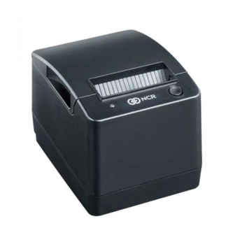
7197 Series II Owner’s Manual Chapter 1: About the 7197 Series II Printer Chapter 1: About the 7197 Series II Printer Receipt Receipt Cover Paper Feed Button Top Cover The 7197 Series II printer is a fast, quiet, relatively small and very reliable multiple- function printer. -
Page 15: Features
7197 Series II Owner’s Manual Chapter 1: About the 7197 Series II Printer Features The 7197 Series II printer comes with several features and options. Receipt Station Thermal printing Standard pitch (host selectable): 15.2 characters per inch, 44 columns ... -
Page 16: General Features
7197 Series II Owner’s Manual Chapter 1: About the 7197 Series II Printer 8) PC Code Page 864 (Arabic) 9) PC Code Page 865 (Nordic) 10) PC Code Page 866 (Cyrillic) 11) PC Code Page 874 (Thai) ... - Page 17 7197 Series II Owner’s Manual Chapter 1: About the 7197 Series II Printer There is no regularly scheduled maintenance for the print head and it does not need to be regularly cleaned. However, if it does appear dirty, wipe it with cotton swabs and rubbing alcohol.
-
Page 18: Ordering Paper And Supplies
Documentation is also available. Ordering Thermal Receipt Paper The 7197 Series II requires NCR qualified thermal paper to be used on the thermal receipt print station to insure proper operation of the printer. In addition the paper rolls must be have the following dimension. -
Page 19: Ordering Other Supplies
9-pin to 9-pin 0.7 meters 1416-C359-0007 9-pin to 9-pin 3.0 meters (9.8 feet) 1416-C266-0040 DC Plus Power Cables DC Power from NCR POS Terminal 1.0 Meters 1416-C712-0010 DC Power from NCR POS Terminal 4.0 Meters 1416-C712-0040 USB Communication Cables USB Type A to Type B Connector 2.0 Meters... -
Page 20: Cleaning The Printer
7197 Series II Owner’s Manual Chapter 1: About the 7197 Series II Printer Cleaning the Printer Cleaning the Cabinet The external cabinet materials and finish are durable and resistant to these items: Cleaning solutions Lubricants Fuels Cooking oils ... -
Page 21: Cleaning The Thermal Print Head
7197 Series II Owner’s Manual Chapter 1: About the 7197 Series II Printer Cleaning the Thermal Print Head Caution: Do not spray or try to clean the thermal print head or the inside of the printer with any kind of cleaner as this may damage the thermal print head and electronics. If the thermal print head appears dirty, wipe it with cotton swabs and isoprophl alcohol. -
Page 22: Chapter 2: Setting Up And Using The Printer
Printer enclosed in a plastic bag and foam pack Thermal receipt paper roll These items may be ordered as options from NCR and will be shipped separately: Communication cable (from host computer to printer) DC Power Cable ... -
Page 23: Removing The Packing Material
7197 Series II Owner’s Manual Chapter 2: Setting Up and Using the Printer Removing the Packing Material Receipt Cover Remove the printer from the foam pack and plastic bag. Remove the receipt paper roll from the foam packing material. Save all packing materials for future storing, moving, or shipping the printer. September 2011... -
Page 24: Repacking The Printer
Place the printer in the plastic bag and foam pack, place the packed printer in the box, and secure the box with packing tape. If you are sending the printer to NCR for repair, call your NCR-authorized service representative for instructions on where to send the printer. -
Page 25: Wall Mounted
7197 Series II Owner’s Manual Chapter 2: Setting Up and Using the Printer Wall mounted The 7197 Series II Series II printer may be mounted on a vertical wall with Wall Mount Kit (Option). Make sure there is enough room to open the receipt cover to change the paper. Mount the screws on the wall using the following recommended mount dimensions. -
Page 26: Setting Switches
7197 Series II Owner’s Manual Chapter 2: Setting Up and Using the Printer Setting Switches The DIP switches, located at the back of the printer, are used for two purposes: To set variables for several printer functions (see the sections for the various printer functions in “Level 1 Diagnostics”... -
Page 27: Connecting The Cables
7197 Series II Owner’s Manual Chapter 2: Setting Up and Using the Printer Resetting the Printer The printer is reset by disconnecting/reconnecting the DC power. Connecting the Cables There are three different types of cables that connect to the printer: ... - Page 28 7197 Series II Owner’s Manual Chapter 2: Setting Up and Using the Printer 7. For Host powered installation plug the DC cable into the POS terminal. RS-232 Cable Connection Communication Power Connector Connector Cash Drawer Connector Communication Power Cash Drawer Cable Cable Cable...
- Page 29 7197 Series II Owner’s Manual Chapter 2: Setting Up and Using the Printer Ethernet Cable Connection (Ethernet model) Cash Drawer Ethernet Connector Power Connector Ethernet Cash Drawer Cable Cable Power Cable Bottom of the Printer September 2011...
-
Page 30: About The Universal Serial Bus
POS printer requirements. Advantages of the NCR USB Solution NCR has eliminated any cost associated with porting applications to USB by implementing a USB solution that simulates standard serial communications in Windows XP. Application developers need only redirect their software to the virtual serial ports created by the NCR USB solution to use the printer. -
Page 31: Checking For Usb Support On The Host Computer
Configuring the Printer USB is a plug-and-play environment. As such, neither the printer nor the host requires user configuration to work. However, since the NCR solution simulates a serial communication interface, you must configure “handshaking” on the printer for proper operation. - Page 32 7197 Series II Owner’s Manual Chapter 2: Setting Up and Using the Printer Receipt Receipt cover Switch DIP Switch Bottom Cover Switch 2 is shown in the OFF position 4. Reset the printer. See below for information on resetting the printer. The printer beeps, prints the current configuration, then waits for you to make a selection from the Main Menu on the printout.
- Page 33 7197 Series II Owner’s Manual Chapter 2: Setting Up and Using the Printer *** Printer Config Menu *** *** Diagnostics Form *** 7197 xxxx-yyyy-zzzz The config menu allows you to set general Model number 01000011 printer parameters. Sub-menus are entered and Serial number selections are made using the Paper Feed Button:...
-
Page 34: Installing The Usb Virtual Com Port Printer Driver When Usb Type Ion (Epic)
7197 Series II Owner’s Manual Chapter 2: Setting Up and Using the Printer Press and hold the Paper Feed button for at least one second for a long click. Press the Paper Feed button quickly for a short click. 5. - Page 35 7197 Series II Owner’s Manual Chapter 2: Setting Up and Using the Printer September 2011...
- Page 36 7197 Series II Owner’s Manual Chapter 2: Setting Up and Using the Printer Note: Location of the IONetworks files on the CD-ROM may very depending on the version of the CD that is being used. September 2011...
- Page 37 7197 Series II Owner’s Manual Chapter 2: Setting Up and Using the Printer September 2011...
- Page 38 7197 Series II Owner’s Manual Chapter 2: Setting Up and Using the Printer September 2011...
-
Page 39: Checking The Installation
7197 Series II Owner’s Manual Chapter 2: Setting Up and Using the Printer Checking the Installation You need to verify that the device drivers were installed correctly: Windows XP: 1. Open the Device Manager window, as you did in “Checking for USB Support.” 2. - Page 40 7197 Series II Owner’s Manual Chapter 2: Setting Up and Using the Printer 3. Scroll back up to “Ports.” If the devices are missing or are not listed correctly, the installation wasn’t successful. You will need to reinstall the drivers. If this information is not listed, then the installation was not successful.
-
Page 41: Configuring Serial Port Number Assignments
You can check the assigned serial port by clicking the General tab in the Edgeport utility. You’ll see an entry for the NCR printer. Expand the list to see which serial port has been assigned to the printer. - Page 42 1. Open the Device Manager and make sure “View Devices By Type” is selected. 2. Scroll down to Universal serial bus controller, and expand the list by pressing the “+” symbol. You’ll see two entries for your NCR printer. 3. Select the printer name and click Properties.
-
Page 43: Using The Printer
7197 Series II Owner’s Manual Chapter 2: Setting Up and Using the Printer Using the Printer Paper Feed Button Note: See “Setting Switches” earlier in this book for instructions on setting the DIP switches. 1. Connect the power supply to the printer and turn on the power source. The printer goes through a self-test routine to ensure everything is working properly then “beeps.”... -
Page 44: Loading And Changing The Receipt Paper
7197 Series II Owner’s Manual Chapter 2: Setting Up and Using the Printer Loading and Changing the Receipt Paper Although the illustrations show a used roll being removed, the instructions apply to loading paper for the first time. Change the paper when either of the following two conditions occurs: ... - Page 45 7197 Series II Owner’s Manual Chapter 2: Setting Up and Using the Printer Receipt cover September 2011...
-
Page 46: Loading The Paper Roll
7197 Series II Owner’s Manual Chapter 2: Setting Up and Using the Printer Loading the Paper Roll Note: Tear off the end of the new roll so that the edge is loose. 1. Place the new roll in the bin with a little extra paper extending over the front. Be sure the paper unrolls from the bottom of the roll. -
Page 47: Advancing Paper
7197 Series II Owner’s Manual Chapter 2: Setting Up and Using the Printer Advancing Paper 1. Press the Paper Feed button on the operator panel to advance the paper. The cover must be closed. To ensure print quality and the proper alignment of the paper, advance about 30 cm (12 inches) of paper. -
Page 48: Chapter 3: Solving Problems
7197 Series II Owner’s Manual Chapter 3: Solving Problems Chapter 3: Solving Problems The 7197 Series II printer is a simple, generally trouble-free printer, but from time to time minor problems may occur. For example, the power supply may be interrupted or the thermal print head may overheat. -
Page 49: Green Led Does Not Come On/Printer Will Not Print
7197 Series II Owner’s Manual Chapter 3: Solving Problems Green LED Does Not Come On/Printer Will Not Print Problem What to Do Where to Go Cables may not be connected Check all cable connections. Check that the See “Connecting the properly host computer and power supply are both on Cables”... -
Page 50: Receipt Printing Is Light Or Spotty
7197 Series II Owner’s Manual Chapter 3: Solving Problems The print head may overheat when printing in See “Environmental a room where the temperature is above the Conditions” in Appendix Thermal print head temperature recommended operating temperature or when A for the recommended is out of range printing high-density graphics continuously, temperature range for... -
Page 51: Other Serious Problems
For serious problems, such as the printer not printing, not communicating with the host computer, or not turning on, contact your NCR-authorized service organization to arrange for a service call. In addition to the service guide listed below, other service-related materials may be available. -
Page 52: Chapter 4: Diagnostics
7197 Series II Service Manual Chapter 3: Diagnostics Chapter 4: Diagnostics The following diagnostic tests are available for the 7197 Series II: Level 0 Diagnostics (Startup) Performed during the startup cycle. Level 1 Diagnostics (Printer Configuration) Allows configuration of the printer using a Configuration Menu that is printed on a receipt. ... -
Page 53: Printer Configuration
7197 Series II Service Manual Chapter 3: Diagnostics Keep the following information in mind when changing the settings: The settings can only be changed when the printer is in level 1 diagnostics (setup mode): Switch 1 must be set to On and Switch 2 must be set to Off. ... - Page 54 7197 Series II Service Manual Chapter 3: Diagnostics Compatible Barcode Length Compress Pitch Setting Hardware Options Receipt Print Mode Print Density Power On Head Failure Detection Maximun Power Options Paper Low Sensor ...
-
Page 55: Configuring The Printer
7197 Series II Service Manual Chapter 3: Diagnostics Configuring the Printer Use the Configuration Menu to select functions or change various settings as indicated in the preceding sections. The Configuration Menu prints instructions and setting options interactively as the user goes through the configuration process. Caution: Be extremely careful in changing any of the printer settings to avoid changing settings that might affect the performance of the printer. - Page 56 7197 Series II Service Manual Chapter 3: Diagnostics For Ethernet Model Select a sub-menu: - EXIT -> 1 Click - Print Current Configuration -> 2 Clicks - Set Communication Interface -> 3 Clicks - Set Diagnostics Modes -> 4 Clicks - Set Emulation/Software ->...
- Page 57 7197 Series II Service Manual Chapter 3: Diagnostics *** Diagnostics Form *** *** Printer Config Menu *** Model number 7197 Series II- The config menu allows you to set general Serial number 5001-9001 printer parameters. Sub-menus are entered 01000011 and selections are made using the Paper Feed Boot Firmware Button: Revision...
-
Page 58: Communication Interface Modes
7197 Series II Service Manual Chapter 3: Diagnostics Communication Interface Modes The Configuration Menu gives the user the option of setting the printer to use an RS-232C serial port. (See “Configuring the Printer” for instructions on how to enter the Configuration Menu.) RS-232C/USB Interface Settings [Standard Model] If the user sets the printer to use an RS-232C serial interface, the Configuration Menu can... - Page 59 7197 Series II Service Manual Chapter 3: Diagnostics ** SET NUMBER OF DATA BITS ? -> Long Click -> Short Click 8 Data Bits* -> Long Click 7 Data Bits -> Short Click ** SET NUMBER OF STOP BITS ? ->...
- Page 60 7197 Series II Service Manual Chapter 3: Diagnostics Disabled -> Short Click ** SET USB INTERFACE TYPE ? -> Long Click -> Short Click ION (EpiC)* -> 1 Click NonION (NHPI) * -> 2 Clicks NonION (PRTR) -> 3 Clicks Enter code, then hold Button DOWN At least 1 second to validate Ethernet Interface Settings [Standard Model]...
-
Page 61: Diagnostic Modes
7197 Series II Service Manual Chapter 3: Diagnostics Diagnostic Modes This function allows the user to put the printer into the following diagnostic modes: Off, Normal Mode: this the normal operating mode of the printer. Datascope Mode: the receipt printer prints incoming commands and data in hexadecimal format. -
Page 62: Emulation/Software Options
7197 Series II Service Manual Chapter 3: Diagnostics 2. Push Paper Feed Button and the receipt station will print all code pages. 3. The test ends with a cut. 4. Go to step 2 again to repeat this test. To exit the Receipt Test Mode: 1. - Page 63 7197 Series II Service Manual Chapter 3: Diagnostics Printer ID Mode This function determines which printer ID is currently effective to the printer. They are set by using the Configuration Menu. (See “Configuring the Printer,” for instructions on how to enter the Configuration Menu.). The available options are: ...
- Page 64 7197 Series II Service Manual Chapter 3: Diagnostics Carriage Return Usage This function allows the printer to ignore or use the Carriage Return (hexadecimal 0D) command depending on the application. Some applicatons expect the command to be ignored while others use the command as a print command. (See “Configuring the Printer”...
- Page 65 7197 Series II Service Manual Chapter 3: Diagnostics Regarding Mode1 and Mode2, The command/status sequence is completely same. The only difference is the printing speed. The printing speed of Mode1 is same as normal printing (max. 12ips). Whereas, the printing speed of Mode2 is 4ips (max) in order to prevent the clatter print in the synchronized line mode.
- Page 66 7197 Series II Service Manual Chapter 3: Diagnostics Set Auto Reset option Set Auto Reset using the configuration menu. Answer No to the questions printed on the receipt until you come to the instructions for Auto Reset. Caution: Be extremely careful changing any of the printer settings to avoid inadvertently changing other settings that might affect the performance of the printer.
- Page 67 7197 Series II Service Manual Chapter 3: Diagnostics Set Compatibility Barcode Length option Set Compatibility Barcode Length using the configuration menu. Answer No to the questions printed on the receipt until you come to the instructions for Compatibility Barcode Length. Caution: Be extremely careful changing any of the printer settings to avoid inadvertently changing other settings that might affect the performance of the printer.
-
Page 68: Hardware Options
Failure to observe this rule may result in a printer service call or voiding of the printer warranty. Consult your NCR technical support specialist if you have any questions. Press the Paper Feed Button for the print density you want. - Page 69 7197 Series II Service Manual Chapter 3: Diagnostics -> 5 Clicks Enter code, then hold Button DOWN At least 1 second to validate Note: Press the Paper Feed Button for at least one second to validate the selection. Maximum Power This function allows the user to set the maximum power for the printer to 75W or 55W.
- Page 70 7197 Series II Service Manual Chapter 3: Diagnostics Note: Press the Paper Feed Button for at least one second to validate the selection. Set Knife Option Set the Knife option using the configuration menu. Answer No to the questions printed on the receipt until you come to the instructions for knife option.
- Page 71 7197 Series II Service Manual Chapter 3: Diagnostics -> Short Click Enable Power LED control* -> Long Click Disable Power LED control -> Short Clicks Set Shift to Standby Enable/Disable the Standby Mode using the configuration menu. This setting is to enable or disable the standby mode.
-
Page 72: Default Code Page
7197 Series II Service Manual Chapter 3: Diagnostics Enabled (60min) -> 1 Click Enabled (120min) -> 2 Clicks Enabled (180min) -> 3 Clicks Enabled (240min) -> 4 Clicks Enabled (300min) -> 5 Clicks Disabled* -> 6 Clicks Enter code, then hold Button DOWN At least 1 second to validate Save Parameters This function allows to save the selected communication settings or return to the... - Page 73 7197 Series II Service Manual Chapter 3: Diagnostics ** SET CODE PAGE ? -> Long Click -> Short Click 7158 Mode: Code Page 437* -> 1 Click Code Page 850 -> 2 Clicks Code Page 852 -> 3 Clicks Code Page 858 ->...
- Page 74 7197 Series II Service Manual Chapter 3: Diagnostics Save new parameters ? -> Long Click NO, MODIFY -> Short Click June 2011...
-
Page 75: Dhcp Mode
7197 Series II Service Manual Chapter 3: Diagnostics DHCP mode Set DIP switch 1 to ON, DIP switch 2 to ON. Ethernet interface: Printer by default starts with DHCP address. “Get IP Address” will be “DHCP” in the Diagnostics Form. In USB interface, this mode will be same as online mode. - Page 76 7197 Series II Service Manual Chapter 3: Diagnostics Rolling ASCII print test (Receipt) This option let you run rolling ASCII printing test. The printer prints the resident character set in standard pitch continuously. Press the Paper Feed Button to start or stop the test. ** START ROLLING ASCII PRINT TEST? Return Main Menu ->...
- Page 77 7197 Series II Service Manual Chapter 3: Diagnostics To stop the test hold the Paper Feed Button down. The printer will return to the Mfg Adjustment Menu. Note: Press the Paper Feed Button for at least one second to validate the selection. Duty check print test (Receipt) This option let you run duty check printing test.
- Page 78 7197 Series II Service Manual Chapter 3: Diagnostics Print current setting This option let you print current setting on receipt. Press the Paper Feed Button to start the test. ** START CURRENT SETTING PRINTING? Return Main Menu -> Short Click Start Printing ->...
- Page 79 7197 Series II Service Manual Chapter 3: Diagnostics EEPROM to Default Setting This selection resets the configuration & clears all input data to the Default Settings. Caution: Don’t perform this selection unless you want to clear all details in EEPROM to default value.
-
Page 80: Level 2 Diagnostics
7197 Series II Service Manual Chapter 3: Diagnostics Level 2 Diagnostics Level 2 diagnostics run during normal printer operation. When the following conditions occur, the printer automatically turns off the appropriate motor, disables printing to prevent damage, and turns on the green LED (flashes the green LED if the receipt print head is too hot or the voltages are out of range): ... -
Page 81: Level 3 Diagnostics
7197 Series II Service Manual Chapter 3: Diagnostics Level 3 Diagnostics Level 3 diagnostics keeps track of the following tallies and prints them on the receipt during the receipt test. Serial number Model number CRC number Number of lines printed ... -
Page 82: Chapter 5: Communication
7197 Series II Owner’s Manual Chapter 5: Communication Chapter 5: Communication Communication Overview In order for a receipt to be printed, a program must be in place that translates the data from the host computer into a language that the printer can understand. This program must tell the printer exactly how to print each character. -
Page 83: Rs-232C Interface (Standard Model)
7197 Series II Owner’s Manual Chapter 5: Communication Using BASIC to Send Commands In BASIC, printer commands are sent as a string of characters preceded by the LPRINT command. For example, LPRINT CHR$(&H0A) sends the hexadecimal number 0A to the printer, which causes the printer to print the contents of its print buffer. -
Page 84: Xon/Xoff Protocol
7197 Series II Owner’s Manual Chapter 5: Communication Char./Line Lines/Receipt Transmit Time: (9600 Baud) Transmit Time: (19.2 K Baud) Print Time 0.4 Seconds 0.2 Seconds 1.2 Seconds 0.8 Seconds 0.4 Seconds 2.4 Seconds 0.88 Seconds 0.44 Seconds 1.2 Seconds 1.76 Seconds 0.88 Seconds 2.4 Seconds XON/XOFF Protocol... -
Page 85: Rs-232C Technical Specifications
7197 Series II Owner’s Manual Chapter 5: Communication RS-232C Technical Specifications This section describes the pin settings for the connectors and the RS-232C interface parameters. The RS-232C parameters are selectable in the Diagnostic mode. See “Diagnostics: Communications Interface Settings” in chapter 4 for the position of the DIP switches. -
Page 86: Ethernet Interface (Ethernet Model)
7197 Series II Owner’s Manual Chapter 5: Communication Ethernet Interface (Ethernet Model) The Ethernet interface uses either 10BASE-t, 100BASE-TX protocol. The Ethernet version of the 7197 Series II offers the web configuration which configure the ethernet settings via Internet browser. See “Communications Interface Settings” later in this book. Protocol Protocol - Physical layer... -
Page 87: Ethernet Connection Port
7197 Series II Owner’s Manual Chapter 5: Communication Item that can be inspected/ changed (Item concerning Ethernet) - IP address - Subnet mask - Default gateway - Get IP address - Community name1 - etc *Please refer to ‘Setting value’ table. -
Page 88: Tcp Socket Communication
7197 Series II Owner’s Manual Chapter 5: Communication TCP Socket communication Communication procedure The TCP socket is used to send commands and data related to printing. And it is also used to send and receive the batch status commands and its statuses. When “Ethernet RTC Protocol”... -
Page 89: Connector
7197 Series II Owner’s Manual Chapter 5: Communication Connector RS 232 Connector The illustration shows the RS-232C communication connector and pin assignments. The connector is a 9-pin male D-shell connector and is located in the hollow cavity under the printer at the rear. Ethernet Connector The Ethernet I/F connector is a 8P8C modular connector (usually called RJ45) with the following pin assignments:... - Page 90 7197 Series II Owner’s Manual Chapter 5: Communication Cash Drawer Connector The following illustration shows the pin out designation for the cash drawer connectors. The following table provides the pinout assignments for cash drawers one and two. The cash drawer connectors are located at the rear of the printer. Pin 1 Pin 6 Pin Number...
-
Page 91: Switch Settings
7197 Series II Owner’s Manual Chapter 5: Communication Switch Settings The DIP switches are located on the PC board at the back of the printer as shown in the illustration in “Level 1 Diagnostics” in chapter 4. The switches are used to put the printer into various modes for printer configuration set Printer End View Use a paper clip or other pointed object to set the switches. -
Page 92: Chapter 6: Commands
The first section lists all of the commands. The following lists are separated into functional category groupings. All commands listed in bold are new or have additional functionality when compared to the NCR 7193. August 2011... -
Page 93: By Command Code
7197 Series II Owner’s Guide Chapter 6: Commands By Command Code All items in BOLD are new or have additional functionality when compared to the 7193. Code (Hexadecimal) Command Page 09 (HT) Horizontal Tab 0A (LF) Print and Feed Paper One Line 0C (FF) Print and Return to Standard Mode 0D (CR) - Page 94 7197 Series II Owner’s Guide Chapter 6: Commands Code (Hexadecimal) Command Page 1B 2A m n1 n2 Select Bit Image Mode d1 … dn 1B 2D n Select or Cancel Underline Mode 1B 2E m n rl rh d1…dn Print Advanced Raster Graphics 1B 32 Set Line Spacing to 1/6 Inch 1B 33 n...
- Page 95 7197 Series II Owner’s Guide Chapter 6: Commands Code (Hexadecimal) Command Page 1C 21 n Select print modes for Kanji characters 1C 2D n Turn underline mode ON/OFF for Kanji 1C 32 c1 c2 d1…dn Define user-defined Kanji characters 1C 53 n1 n2 Set Kanji character spacing 1c 57 n Set quadruple mode ON/OFF for Kanji...
- Page 96 7197 Series II Owner’s Guide Chapter 6: Commands Code (Hexadecimal) Command Page 1D 56 m n Select Cut Mode and Cut Paper 1D 57 nL nH Set Printing Area Width 1D 5C nL nH Set Relative Vertical Print Position in Page Mode 1D 5E r t m Execute Macro...
-
Page 97: By Function
7197 Series II Owner’s Guide Chapter 6: Commands By Function All items in BOLD are new or have additional functionality when compared to the 7193. Printer Function Commands Code (Hexadecimal) Command Page Clear Printer 19 or 1B 69 Perform Full Knife Cut 1A or 1B 6D Perform Partial Knife Cut 1B 07... -
Page 98: Horizontal Positioning Commands
7197 Series II Owner’s Guide Chapter 6: Commands Horizontal Positioning Commands Code (Hexadecimal) Command Page Horizontal Tab 1B 14 n Set Column 1B 24 n1 n2 Set Absolute Starting Position 1B 44 [n] k 00 Set Horizontal Tabs 1B 5C n1 n2 Set Relative Print Position 1B 61 n Select Justification... -
Page 99: Graphics Commands
7197 Series II Owner’s Guide Chapter 6: Commands Code (Hexadecimal) Command Page 1D 42 n Select or Cancel White/Black Reverse Print Mode 1F 05 n Select Superscript or Subscript Modes Graphics Commands Code (Hexadecimal) Command Page 11 n1 ... nk Print Raster Graphics 1B (+*.bmp) Download BMP Logo... -
Page 100: Status Commands
7197 Series II Owner’s Guide Chapter 6: Commands Status Commands Batch Mode Code (Hexadecimal) Command Page 1B 75 0 Transmit Peripheral Device Status 1B 76 Transmit Paper Sensor Status 1D 49 n Transmit Printer ID 1D 49 40 n Transmit Printer ID, Remote Diagnostics Extension 1D 72 n Transmit Status... -
Page 101: Barcode Commands
7197 Series II Owner’s Guide Chapter 6: Commands Barcode Commands Code (Hexadecimal) Command Page 1D 48 n Select Printing Position for HRI Characters 1D 66 n Select Pitch for HRI Characters 1D 68 n Select Bar Code Height 1D 6B m d1…dk 00 Print Bar Code 1D 6B m n d1…dn 1D 77 n... -
Page 102: Macro Commands
7197 Series II Owner’s Guide Chapter 6: Commands Macro Commands Code (Hexadecimal) Command Page 1D 3A Start or End Macro Definition 1D 5E r t m Execute Macro User Data Storage Commands Code (Hexadecimal) Command Page 1B 27 m addr d1…dm Write to User Data Storage 1B 34 m addr Read from User Data Storage... -
Page 103: Comparison Chart
7197 Series II Owner’s Guide Chapter 6: Commands 1D 0E Erase the Flash Memory 1D 0F Return Main Program Flash CRC 1D 10 n Erase Selected Flash Sector 1D 11 aL aH cL cH Download to Active Flash Sector d1…dn 1D FF Reboot the Printer Comparison Chart... -
Page 104: Command Descriptions
7197 Series II Owner’s Guide Chapter 6: Commands Command Description Difference between 7193 and 7197 Series II configured in 7193 Emulation Mode. the 7193 had a fundamental step of 1/152 inch and the 7197 Series II has a fundamental step of 1/203 inch, the actual line spacing will not exactly match the requested spacing. -
Page 105: Printer Function Commands
7197 Series II Owner’s Guide Chapter 6: Commands Name: Name of Command ASCII: The ASCII representation of the command control code followed by its operands. Hexadecimal: The hexadecimal representation of the command control code followed by its operands. Decimal: The decimal representation of the command control code followed by its operands. - Page 106 7197 Series II Owner’s Guide Chapter 6: Commands Clear Printer ASCII: Hexadecimal: Decimal: Clears the print line buffer without printing and sets the printer to the following condition: 1. Double-Wide command (0x12) is cancelled 2. Line Spacing, Pitch, and User-Defined Character Sets are maintained at current selections (RAM is not affected) 3.
- Page 107 7197 Series II Owner’s Guide Chapter 6: Commands Perform Partial Knife Cut (Previously command was full knife cut) ASCII: ESC i Hexadecimal: 1B 69 27 105 Decimal: Cuts the receipt, leaving .20 inch (5 mm) of paper. This command is implemented the same as Partial Knife Cut (1A, 1B 6D).
- Page 108 7197 Series II Owner’s Guide Chapter 6: Commands Generate Tone ASCII: ESC BEL 1B 07 Hexadecimal: 27 7 Decimal: Generates an audible tone. This allows the application to provide an audiable tone to the operator. Example: MSComm1.Output = Chr$(&H1B) & Chr$(&H07) Initialize Printer ASCII: ESC @...
- Page 109 7197 Series II Owner’s Guide Chapter 6: Commands Select Sensors to Stop Printing ASCII: ESC c 4 n Hexadecimal: 1B 63 34 n Decimal: 27 99 52 n Value of n : Function 0, 1 Stop Receipt on Receipt Low 2 - 7 Undefined Default:...
- Page 110 7197 Series II Owner’s Guide Chapter 6: Commands Generate Pulse to Open Cash Drawer ASCII: ESC p n p1 p2 Hexadecimal: 1B 70 n p1 p2 Decimal: 27 112 n p1 p2 Value of n : 0, 48 = Drawer 1 1, 49 = Drawer 2 Value of p1: 0 - 255...
-
Page 111: Print Test Form
7197 Series II Owner’s Guide Chapter 6: Commands Feed and Cut Mode 0, 48 Full cut (no extra feed). Partial cut on the Sam. 1, 49 Partial cut (no extra feed). Feeds paper to cutting position + (n times vertical motion unit), and cuts the paper completely. -
Page 112: Vertical Positioning And Print Commands
7197 Series II Owner’s Guide Chapter 6: Commands This command is available in 7194 Native Mode and 7197 Series II Native Mode only. Vertical Positioning and Print Commands The vertical positioning and print commands control the vertical print positions of characters on the receipt. -
Page 113: Feed N Print Lines
7197 Series II Owner’s Guide Chapter 6: Commands Feed n Print Lines ASCII: DC4 n Hexadecimal: 14 n 20 n Decimal: Value of n: The number of lines to feed at current line height setting. 0 – 127 7193 Emulation Mode Range of n : and 7197 Series II 0 –... -
Page 114: Add N Extra Dot Rows
7197 Series II Owner’s Guide Chapter 6: Commands Add n Extra Dot Rows ASCII: SYN n 16 n Hexadecimal: 22 n Decimal: Value of n: n/203 inch Range of n: 0 - 12 Default: Adds n extra dot rows to the character height to increase space between print lines or decrease number of lines per inch. -
Page 115: Print
7197 Series II Owner’s Guide Chapter 6: Commands Print ASCII: Hexadecimal: Decimal: Prints one line from the buffer and feeds paper one line. Executes LF on receipt. Example: MSComm1.Output = Chr$(&H17) Set Line Spacing to 1/6 Inch ESC 2 ASCII: Hexadecimal: 1B 32... -
Page 116: Print And Feed Paper
7197 Series II Owner’s Guide Chapter 6: Commands Sets the line spacing to n/406 inches. The minimum line spacing is 8.5 lines per inch. The line spacing equals the character height when n is too small. If the Set Horizontal and Vertical Minimum Motion Units command (1D 50) is used to change the horizontal and vertical minimum motion unit, the parameters of this command (Set Line Spacing) will be interpreted accordingly. -
Page 117: Print And Feed N Lines
7197 Series II Owner’s Guide Chapter 6: Commands Print and Feed n Lines ASCII: ESC d n Hexadecimal: 1B 64 n 27 100 n Decimal: Value of n: Number of lines to be printed and fed. Range of n: 1 – 255 (0 is interpreted as 1 on the receipt station) Prints one line from the buffer and feeds paper n lines at the current line height. -
Page 118: Horizontal Positioning Commands
7197 Series II Owner’s Guide Chapter 6: Commands Horizontal Positioning Commands The horizontal positioning commands control the horizontal print positions of characters on the receipt. Horizontal Tab ASCII: Hexadecimal: Decimal: Moves the print position to the next tab position set by the Set Horizontal Tab Positions (1B 44 n1 n2 ... -
Page 119: Set Absolute Starting Position
7197 Series II Owner’s Guide Chapter 6: Commands Set Absolute Starting Position ASCII: ESC $ n1 n2 Hexadecimal: 1B 24 n1 n2 Decimal: 27 36 n1 n2 Value of n: Number of dots to be moved from the beginning of the line. -
Page 120: Set Horizontal Tabs
7197 Series II Owner’s Guide Chapter 6: Commands Set Horizontal Tabs ASCII: ESC D [n] k NUL Hexadecimal: 1B 44 [n] k 00 27 68 [n] k 0 Decimal: Value of n: Column for tab minus one. n is always less than or equal to the current selected column width. -
Page 121: 1B 5C N1 N2
7197 Series II Owner’s Guide Chapter 6: Commands Set Relative Print Position ASCII: ESC \ n1 n2 1B 5C n1 n2 Hexadecimal: 27 92 n1 n2 Decimal: Value of n: To Move the Relative Starting Position Right of the Current Position by n dots: n1 = Remainder after dividing n by 256. -
Page 122: Select Justification
7197 Series II Owner’s Guide Chapter 6: Commands (Set Relative Print Position) will be interpreted accordingly. For more information, see the description of the Set Horizontal and Vertical Minimum Motion Units command (1D 50) in this document. Compatibility Information (7194 Native Mode and 7197 Series II Native Mode receipt vs. 7193 receipt) There is a difference in the normal behavior of this command in 7194 Native Mode and 7197 Series II Native Mode as compared to the original 7193. -
Page 123: 1D 4C Nl Nh
7197 Series II Owner’s Guide Chapter 6: Commands Set Left Margin ASCII: GS L nL nH Hexadecimal: 1D 4C nL nH Decimal: 29 76 nL nH Range of nL: 0 - 255 Range of nH: 0 - 255 Default: 80 mm width 576 dots (the maximum printable area) 58 mm width 424 dots (the maximum printable area) -
Page 124: 1D 57 Nl Nh
7197 Series II Owner’s Guide Chapter 6: Commands Set Printing Area Width ASCII: GS W nL nH Hexadecimal: 1D 57 nL nH 29 87 nL nH Decimal: Range of nL: 0 – 255 Range of nH: 0 - 255 Default: 80 mm width 576 dots (the maximum printable area) 58 mm width... -
Page 125: Print Characteristic Commands
7197 Series II Owner’s Guide Chapter 6: Commands This command is ignored if the line buffer is not empty, and only effects the Receipt interface. If the setting exceeds the printable area, the maximum value of the printable area is used. The maximum printable area is 576 dots for 80 mm paper width and 424 dots for 58 mm paper width. -
Page 126: Select 90 Degree Counter-Clockwise Rotated Print
7197 Series II Owner’s Guide Chapter 6: Commands Select 90 Degree Counter-Clockwise Rotated Print ASCII: ESC DC2 Hexadecimal: 1B 12 Decimal: 27 18 Rotates characters 90 degrees counter-clockwise. The command remains in effect until the printer is reset or until a Clear Printer (0x10), Select or Cancel Upside-Down Print (1B 7B), or Select or Cancel Rotated Print (1B 56) command is received. -
Page 127: Set Character Right-Side Spacing
7197 Series II Owner’s Guide Chapter 6: Commands Pitch Columns Standard 44 for 80 mm 15.6 paper 32 for 58 mm paper Compressed 56 for 80 mm 20.3 paper 42 for 58 mm paper Example: MSComm1.Output = Chr$(&H1B) & Chr$(&H16) & Chr$(n) Related Information: See “Technical Specifications”... -
Page 128: Select Print Modes
7197 Series II Owner’s Guide Chapter 6: Commands lower left of the printable area (set by Select Print Direction in Page Mode, 1B 54 n) the vertical motion unit (y) is used. Example: MSComm1.Output = Chr$(&H1B) & Chr$(&H20) & Chr$(n) Exception: This command is ignored in 7193 Emulation Mode and is only valid on the receipt station. -
Page 129: Select Or Cancel User-Defined Character Set
7197 Series II Owner’s Guide Chapter 6: Commands Double-wide Single-wide 1B 2D n Underline Limitation: In Diagnostic setting, if “Compress Pitch” setting is “Ignore” then setting the Compressed pitch(Bit 0) using this command will be ignored Select or Cancel User-Defined Character Set ASCII: ESC % n Hexadecimal:... - Page 130 7197 Series II Owner’s Guide Chapter 6: Commands Defines and enters downloaded characters into RAM or Flash. The command may be used to overwrite single characters. User-defined characters are available until power is turned off or the Initialize Printer command (1B 40) is received. Any invalid byte (s, c1, c2, n1) aborts the command.
-
Page 131: Select Or Cancel Underline Mode
7197 Series II Owner’s Guide Chapter 6: Commands Select or Cancel Underline Mode ASCII: ESC - n Hexadecimal: 1B 2D n 27 45 n Decimal: Value of n: 0, 48 = Cancel underline mode 1, 49 = Select underline mode Default of n: 0 (Cancels underline mode) Turns underline mode on or off. -
Page 132: Cancel User-Defined Characters
7197 Series II Owner’s Guide Chapter 6: Commands To modify characters in one of the character set variations, such as Rotated Print, select one of the Rotated Print commands, copy to RAM, then use the Define User-Defined Character Set command (1B 26). Cancel User-Defined Characters ASCII: ESC ? n... - Page 133 7197 Series II Owner’s Guide Chapter 6: Commands Related Information: This command and the Select Print Mode(s) command (1B 21) function identically. Select or Cancel Double Strike ASCII: ESC G n Hexadecimal: 1B 47 n Decimal: 27 71 n Value of n: 0 = Off 1 = On Turns double strike mode on or off.
- Page 134 7197 Series II Owner’s Guide Chapter 6: Commands 0 (Off) Default: Turns Italic print mode on or off. This command is only available in 7194 Native Mode and 7197 Series II Native Mode. Italic print mode is available for built-in, user-defined characters.
- Page 135 7197 Series II Owner’s Guide Chapter 6: Commands 22 = Code Page 864 Arabic 127 = Hungary 128 = Code Page 932 129 = Code Page 936 130 = Code Page 949 131 = Code Page 950 0 (Code Page 437) Default: Selects the character set to be used.
- Page 136 7197 Series II Owner’s Guide Chapter 6: Commands Select Print Color ASCII: ESC r n Hexadecimal: 1B 72 n Decimal: 27 114 n Value of n: 0 = Monochrome 1 = 2 Color Default: 0 (Monochrome) Selects color printing. Color printing is valid for character, graphics, logo and barcode. ...
- Page 137 7197 Series II Owner’s Guide Chapter 6: Commands Hexadecimal: 1D 21 n Decimal: 29 33 n Value of n: 1 - 8 = vertical number of times normal font 1 – 8 = horizontal number of times normal font Range of n: 00 –...
- Page 138 7197 Series II Owner’s Guide Chapter 6: Commands The Select Print Mode (1B 21 n) command can also select or cancel double-width and double-height modes. However, the setting of the last received command is effective. Example: MSComm1.Output = Chr$(&H1D) & Chr$(&H21) & Chr$(n) Exceptions: If n is out of the defined range, this command is ignored.
- Page 139 7197 Series II Owner’s Guide Chapter 6: Commands Select or Cancel Smoothing Mode ASCII: GS b n Hexadecimal: 1D 62 n Decimal: 29 98 n This command is ignored. Example: MSComm1.Output = Chr$(&H1D) & Chr$(&H62) & Chr$(n) Select Superscript or Subscript Modes ASCII: US ENQ n...
- Page 140 7197 Series II Owner’s Guide Chapter 6: Commands 27 43 n Decimal: Value of n: 0 = not select (Normal code) 1 = selected (Uni-code(UTF-16)) Default: 0 (normal code) Starts or stops specified by Unicode(UTF-16). Note: In Unicode mode, characters are specified as follows. ESC + 1 <nL>...
-
Page 141: Graphics Commands
7197 Series II Owner’s Guide Chapter 6: Commands Graphics Commands These commands are used to enter and print graphics data and are described in order of their hexadecimal codes. Print Raster Graphics ASCII: DC1 n1 … nk Hexadecimal: 11 n1 … nk Decimal: 17 n1 …... - Page 142 7197 Series II Owner’s Guide Chapter 6: Commands The downloaded BMP file can be printed by using the Print Downloaded Bit Image (1D 2F m) command. Example: 1. MSComm1.Output = Chr$(&H1B) Open bitmapfile For Binary As filehandle filecontent = Input(LOF(filehandle), filehandle) MSComm1.Output = filecontent &...
- Page 143 7197 Series II Owner’s Guide Chapter 6: Commands 0-212 (101DPI, 24x212 58mm) (58mm) 24 Dot 24 (203 DPI) 0-576 (101DPI, 24x576 Double 80mm) (80mm) Density 0-424 (101DPI, 24x424 58mm) (58mm) Formulas: 8 Dot Single Density n1 + (256 x n2) 24 Dot Single Density 3 x [n1 + (256 x n2)] 8-Dot Single-Density Mode—Receipt...
- Page 144 7197 Series II Owner’s Guide Chapter 6: Commands Print Advanced Raster Graphics ASCII: ESC . m n rl rh d1 … dn 1B 2E m n rl rh d1 … dn Hexadecimal: 27 46 m n rl rh d1 … dn Decimal: Value of m: Horizontal offset from left margin = 8 x n dots...
- Page 145 7197 Series II Owner’s Guide Chapter 6: Commands Enters one line of 8-dot single-density graphics into the print buffer. Any print command is required to print the line, after which the printer returns to normal processing mode. The number of bytes sent is represented by the formulas in the table. Each bit corresponds to one horizontal dot.
- Page 146 7197 Series II Owner’s Guide Chapter 6: Commands Select the Current Logo (Downloaded Bit Image) ASCII: GS # n 1D 23 n Hexadecimal: 29 35 n Decimal: Range of n: 0 – 255 Selects a logo to be defined or printed. The active logo n remains in use until this command is sent again with a different logo n.
- Page 147 7197 Series II Owner’s Guide Chapter 6: Commands Define Downloaded Bit Image ASCII: GS * n1 n2 d1 ... dn] 1D 2A n1 n2 d1 ... dn] Hexadecimal: 29 42 n1 n2 d1 ... dn Decimal: Value of n1: See the following table. Value of n2: See the following table.
- Page 148 7197 Series II Owner’s Guide Chapter 6: Commands Top of G raphic C olum n C olum n O ne 72 x 8 M ax. R ow O ne M S B R ow 64 M ax. Exceptions: See the illustration for the Print Downloaded Bit Image command (1D 2F) for a representation of the bit image.
- Page 149 7197 Series II Owner’s Guide Chapter 6: Commands Print Downloaded Bit Image ASCII: GS / m Hexadecimal: 1D 2F m Decimal: 29 47 m Value and Range of m: Value of m Print Mode Vertical DPI Horizontal DPI* Normal Double Wide Double High Quadruple Dot density measured in dots per inch...
- Page 150 7197 Series II Owner’s Guide Chapter 6: Commands Convert 6 Dots/mm Bitmap to 8 Dots/mm Bitmap ASCII: US EOT n Hexadecimal: 1F 04 n Decimal: 31 04 n Value: 0 = Off 1 = On Default: 0 (Off) Selects or cancels 6 dot/mm Emulation Mode. When the 6 dot/mm emulation is selected, logos and graphics are expanded horizontally and vertically to emulate their size on a 6 dot/mm printer.
-
Page 151: Status Commands
7197 Series II Owner’s Guide Chapter 6: Commands Status Commands Status Command Introduction The 7197 Series II has three methods of providing status to the application. These methods are through Batch Status Commands, Real Time Status Commands, and Auto Status Back. An application may use one or more of these methods to understand the current status of the printer. - Page 152 7197 Series II Owner’s Guide Chapter 6: Commands Transmit Peripheral Device Status ASCII: ESC u 0 Hexadecimal: 1B 75 0 27 117 0 Decimal: Bit 0 Bit 1 1 = Drawer 1 closed 1 = Drawer 2 closed Return Value: 0 = Drawer 1 open 0 = Drawer 2 open (Bits 2-7 are not used)
- Page 153 7197 Series II Owner’s Guide Chapter 6: Commands Transmit Printer Status ASCII: ESC v Hexadecimal: 1B 76 Decimal: 27 118 Sends status data to the host computer. The printer sends one byte to the host computer when it is not busy or in a fault condition. In DTR/DSR protocol, the printer waits for DSR = SPACE.
- Page 154 Printer model ID NCR 7194 0x24 1, 49 Printer model ID NCR 7193 0x03 1, 49 Printer model ID NCR 7197 Series II 0xA2 2, 50 Type ID Installed options Refer to the table below 3, 51 ROM version ID ROM version...
- Page 155 7197 Series II Owner’s Guide Chapter 6: Commands Type ID (n=4) Off/On Decimal Function No logo definition loaded by application. Logo loaded by application. Undefined Undefined Undefined Not used. Fixed to Off. Undefined Undefined Not used. Fixed to Off. Example: ...
- Page 156 7197 Series II Owner’s Guide Chapter 6: Commands When an application uses UDP 3000 port, adding 4bytes of Sequence Number before command is required. e.g) Flash Firmware version command, send xxh xxh xxh xxh 1Dh 49h 40h A3h. “xxh xxh xxh xxh“ is Sequence Number. The printer returns the response with the same Sequence Number.
- Page 157 7197 Series II Owner’s Guide Chapter 6: Commands Value of n Remote Diagnostic Item Function DBCS (for Receipt) Return DBCS (for Receipt) version, a version, 4 digit ASCII total of 6 bytes DBCS (for Slip) version, Return DBCS (for Slip) version, a 4 digit ASCII total of 6 bytes Ç...
- Page 158 7197 Series II Owner’s Guide Chapter 6: Commands Value of n Remote Diagnostic Item Function Flash cycles tally Return Flash cycles cut tally, returns 10 bytes ¿ Knife jams tally, Write to NVRAM 8 digit ASCII numeric, max 99,999,999 ┌ Knife jams tally Write to NVRAM, and print on receipt to verify...
- Page 159 7197 Series II Owner’s Guide Chapter 6: Commands Value of n Remote Diagnostic Item Function Dot Failure Clear Dot Failure Information(-1 Information(-1 Warning Warning Dot) on tally to 0. Dot) on tally, 3 digit ASCII numeric Dot Failure Return Dot Failure Information(-1 Information(-1 Warning Warning Dot) on tally, a total of 5 Dot) on tally, 3 digit...
- Page 160 7197 Series II Owner’s Guide Chapter 6: Commands Transmits the status specified by n. This is a batch mode command which transmits the response after all prior data in the receive buffer has been processed. There may be a time lag between the printer receiving this command and transmitting the response, depending on the receive buffer status.
- Page 161 7197 Series II Owner’s Guide Chapter 6: Commands Flash logo area adequate. Definition stored. Flash logo area not adequate for recent definition. Not used. Fixed to off. No thermal user-defined characters written to Flash Thermal user-defined characters written to Flash. Not used.
- Page 162 7197 Series II Owner’s Guide Chapter 6: Commands MSComm1.Output = Chr$(&H1F) & Chr$(&H56) Execute Head Failure Detection ASCII: US SUB 02 00 Hexadecimal: 1F 1A 02 00 Decimal: 31 26 02 00 Response: Result of the Head Failure Detection (3bytes) Response format table (3bytes) Description Byte #1...
- Page 163 7197 Series II Owner’s Guide Chapter 6: Commands The printer returns the print completion response when it finishes printing the data sent before this command. The printable data sent before this command is identified by the parameter of this command. This command specifies ID for print data sent before this command.
- Page 164 7197 Series II Owner’s Guide Chapter 6: Commands GS ENQ 1D 05 Binary Binary XOFF Binary August 2011...
-
Page 165: Real Time Commands
7197 Series II Owner’s Guide Chapter 6: Commands Real Time Commands These commands provide an application interface to the printer even when the printer is not handling other commands (RS-232C communication interface only): 1. Real Time Status Transmission (GS Sequence and DLE Sequence) 2. - Page 166 7197 Series II Owner’s Guide Chapter 6: Commands Third, care must be taken not to insert a Real Time command into the data sequence of another command that consists of two or more bytes. In this case the printer will use the real time command sequence bytes instead of the other command’s parameter bytes when finally executing that other command from the buffer;...
- Page 167 7197 Series II Owner’s Guide Chapter 6: Commands Real Time Status Transmission GS Sequence DLE Sequence Non ION USB Standard/Ethernet Standard/Ethernet ASCII: GS EOT n DLE EOT n DC4 SOH n (bRequest = DC4, wValue = SOH n) Hexadecimal: 1D 04 n 10 04 n 14 01 n (bRequest = 0x14, wValue = 0x01 n)
- Page 168 7197 Series II Owner’s Guide Chapter 6: Commands Transmits the selected one byte printer status specified by n in Real Time according to the following parameters. This command includes two sequences: GS and DLE and using either or will produce the same result. ...
- Page 169 7197 Series II Owner’s Guide Chapter 6: Commands 3 = Transmit Error Status Status Decimal Function Fixed to Off Fixed to On Fixed to Off No knife error Knife error occurred Fixed to On No unrecoverable error Unrecoverable error occurred Thermal print head temp./power supply voltage are in range Thermal print head temp./power...
- Page 170 7197 Series II Owner’s Guide Chapter 6: Commands Not used. Fixed to off. Real Time Request to Printer GS Sequence DLE Sequence Non ION USB Standard/Ethernet Standard/Ethernet ASCII: GS ETX n DLE ENQ n NAK STX n (bRequest = NAK, wValue = STX n) Hexadecimal: 1D 03 n...
- Page 171 7197 Series II Owner’s Guide Chapter 6: Commands preserved with this command. This sequence is ignored except when the printer is busy due to an error condition. Example: MSComm1.Output = Chr$(&H1D) & Chr$(&H03) & Chr$(n) Exceptions: The command is ignored if n is out of range An application using the DLE sequence must send ENQ within 100 milliseconds of DLE or the printer will misinterpret the DLE and execute a Clear Printer command.
- Page 172 7197 Series II Owner’s Guide Chapter 6: Commands Cover closed Cover open Not busy at the RS-232C interface Printer is busy at the RS-232C interface One or both cash drawers open Both cash drawers closed Fixed to off No error condition Error condition exists in the printer Fixed to on ...
-
Page 173: Unsolicited Status Update Validation
7197 Series II Owner’s Guide Chapter 6: Commands Unsolicited Status Update Validation Determine if Device Supports USU The Host uses this command to determined if the device supports USU ASCII: GS a x Hexadecimal: 1D 61 x Decimal: 29 97 x Value o f x 0 - FF Response To Host (Hex): 1A, 9F, 1F... - Page 174 7197 Series II Owner’s Guide Chapter 6: Commands Baseline State Request This request tells the printer to send an Unsolicited Status Update message for all Sensors and States supported by the firmware. This allows the Application, Driver, or Control to establish an initial picture of the state of the printer.
- Page 175 7197 Series II Owner’s Guide Chapter 6: Commands Status Update Messages Defined The following table defines the sensor or state information specified by each identifier value, and the meaning of the information in the lower 4 bits of the 3 byte for that identifier value.
- Page 176 7197 Series II Owner’s Guide Chapter 6: Commands Identifier Description of sensor or state State Meaning Value (Hex) RTC Sensor Bit if Applicable for 7167 / 7197 Series Value ( Note: RTC might be different for other printers ) Knife Condition Knife in Error Condition RTC Response ( 10 04 03 ) –...
- Page 177 7197 Series II Owner’s Guide Chapter 6: Commands Printer Firmware Implementation Considerations The printer firmware will constantly monitor the states listed above. Once the Enable USU command has been received, from that time forward until the Disable USU command is received, the printer firmware should transmit a USU message anytime there is a change to a state.
-
Page 178: Bar Code Commands
7197 Series II Owner’s Guide Chapter 6: Commands Bar Code Commands These following describes the commands for the printing of bar codes and described in the order of their hexadecimal codes. Note: 7193 firmware can be set for module widths in bar codes ranging from 2 dots to 4 dots per module (DPM) for the narrow modules. - Page 179 7197 Series II Owner’s Guide Chapter 6: Commands Select Pitch for HRI Characters ASCII: GS f n Hexadecimal: 1D 66 n 29 102 n Decimal: Value of n: Pitch 0 = Standard Pitch at 15.2 CPI on receipt 1 = Compressed Pitch at 19 CPI on receipt Default: 0 (Standard Pitch at 15.2 CPI) Selects standard or compressed font for printing Bar Code characters.
- Page 180 7197 Series II Owner’s Guide Chapter 6: Commands Print Bar Code First Variation Second Variation ASCII: GS k m d1…dk NUL GS k m n d1…dn Hexadecimal: 1D 6B m d1…dk 00 1D 6B m n d1…dn 29 107 m d1…dk 0 29 107 m n d1…dn Decimal: 0 = End of command.
- Page 181 7197 Series II Owner’s Guide Chapter 6: Commands Bar Code n, Length UPC-A 48- 57 (ASCII numerals) Fixed Length: 11, 12 UPC-E 48- 57 Fixed Length: 11, 12 JAN13 (EAN13) 48- 57 Fixed Length: 12, 13 JAN8 (EAN8) 48- 57 Fixed Length: 7, 8 Code 39 48- 57,...
- Page 182 7197 Series II Owner’s Guide Chapter 6: Commands Bar Code n, Length UPC-A 48- 57 (ASCII numerals) Fixed Length: 11, 12 UPC-E 48- 57 Fixed Length: 11, 12 JAN13 (EAN13) 48- 57 Fixed Length: 12, 13 JAN8 (EAN8) 48- 57 Fixed Length: 7, 8 CODE 39 48- 57, 65- 90 (ASCII...
- Page 183 7197 Series II Owner’s Guide Chapter 6: Commands 48 <= d1 <= 57, 48 <= d2 <= 57] GS1 DataBar 32 - 34, 37 - 47, 48 - 57, Variable length Expanded 58 - 63, 65 - 90, 95, (2 - 70) Stacked 97 - 122, 123 [However d1 = 40, 48 <=...
- Page 184 7197 Series II Owner’s Guide Chapter 6: Commands In order to express AI in HRI, AI is surrounded by the bracket and printed. Because this parenthesis needs to distinguish from the usual data, it is necessary to use special data. In the case of Expanded and Expanded stacked, C/D is used for only HRI characters printing.
-
Page 185: Caution
7197 Series II Owner’s Guide Chapter 6: Commands Select Bar Code Width ASCII: GS w n Hexadecimal: 1D 77 n 29 119 n Decimal: Value of n: 1, 2, 3, 4, 5 Default: 3 for receipt Sets the bar code width to n dots. Formulas: n + 1/8 mm (n + 1/203 inch) for receipt. - Page 186 7197 Series II Owner’s Guide Chapter 6: Commands Selects the model for QR Code. QR Code: Set the size of module ASCII: GS ( k pL pH cn fn n 1D 28 6B pL pH cn fn n Hexadecimal: Decimal: 29 40 107 pL pH cn fn n pL, pH specify (pL + pH 256) as the number...
- Page 187 7197 Series II Owner’s Guide Chapter 6: Commands When model1 or model2 selected n=48,49,50,51 When microQR selected n=48,49,50 Default n: Selects the error correction level for QR Code. Note: In MicroQR, it is not printed error correction level='H' at the time of the choice. 'Symbol versionM1' in microQR.
- Page 188 7197 Series II Owner’s Guide Chapter 6: Commands Value of cn: Value of fn: Value of m: Encodes and prints the QR Code symbol data in the symbol storage area with GS ( k Note : User must secure the quiet zone (left, right, upward, and downward space areas defined by the QR Code symbol specifications) for QR Code printing.
- Page 189 7197 Series II Owner’s Guide Chapter 6: Commands Horizontal and vertical sizes are specified as ASCII value of received byte. They can be obtained by following equations. Horizontal size = Number of cells in Horizontal Direction × Symbol size specified by the command 1D 28 6B 03 00 31 43 n Vertical size = Number of cells in Vertical Direction ×...
- Page 190 7197 Series II Owner’s Guide Chapter 6: Commands Page Mode Commands Page Mode is one of two modes, which the 7194 printer uses to operate. Standard Mode is typical of how most printers operate by printing data as it is received and feeding paper as the various paper feed commands are received.
- Page 191 7197 Series II Owner’s Guide Chapter 6: Commands Cancel Print Data in Page Mode ASCII: Hexadecimal: Decimal: Deletes all the data to be printed in the “page” area. Any data from the previously selected “page” area that is also part of the current data to be printed is deleted. This command has the same code as the Open Form command, which is performed when the printer is not in Page Mode.
- Page 192 7197 Series II Owner’s Guide Chapter 6: Commands Select Page Mode ASCII: ESC L Hexadecimal: 1B 4C 27 76 Decimal: Switches from Standard Mode to Page Mode. After printing has been completed either by the Print and Return to Standard Mode (FF) command or Select Standard Mode (1B 53) the printer returns to Standard Mode.
- Page 193 7197 Series II Owner’s Guide Chapter 6: Commands Sel7ect Standard Mode ASCII: ESC S 1B 53 Hexadecimal: 27 83 Decimal: Switches from Page Mode to Standard Mode. In switching from Page Mode to Standard Mode, data buffered in Page Mode is cleared, the printing area set by Set Print Area in Page Mode (1B 57) is initialized and the print position is set to the beginning of the line.
- Page 194 7197 Series II Owner’s Guide Chapter 6: Commands Select Print Direction in Page Mode ASCII: ESC T n Hexadecimal: 1B 54 n 27 84 n Decimal: Value of n: Start position Upper left corner proceeding across page to the right (A) Lower left corner proceeding up the page (B) Lower right corner proceeding across page to the left (upside down) (C)
- Page 195 7197 Series II Owner’s Guide Chapter 6: Commands Set Printing Area in Page Mode ASCII: ESC W n1, n2 ...n8.] Hexadecimal: 1B 57 n1, n2 ...n8] Decimal: 27 87 n1,n2 ...n8] Range: 0 - 255 n1-4 = 0 Default: n5 = 64 n6 = 2 n7 = 64 n8 = 2...
- Page 196 7197 Series II Owner’s Guide Chapter 6: Commands MSComm1.Output = Chr$(&H1B) & Chr$(&H57) & Chr$(&H40) & Chr$(&H0) & Chr$(&H40) & Chr$(&H0) & Chr$(&H40) & Chr$(&H1) & Chr$(&H40) & Chr$(&H1) Exception: This command is effective only in Page Mode. Set Absolute Vertical Print Position in Page Mode ASCII: GS $ nL nH Hexadecimal:...
- Page 197 7197 Series II Owner’s Guide Chapter 6: Commands Set Relative Vertical Print Position in Page Mode ASCII: GS \ nL nH Hexadecimal: 1D 5C nL nH 29 92 nL nH Decimal: Sets the relative vertical print starting position from the current position. This command can also change the horizontal and vertical motion unit.
-
Page 198: Macro Commands
7197 Series II Owner’s Guide Chapter 6: Commands Macro Commands These commands are used to select and perform a user-defined sequence of printer operations. Start or End Macro Definition GS : ASCII: Hexadecimal: 1D 3A Decimal: 29 58 Starts or ends macro definition. Macro definition begins when this command is received during normal operation and ends when this command is received during macro definition. - Page 199 7197 Series II Owner’s Guide Chapter 6: Commands Execute Macro ASCII: GS ^ r t m Hexadecimal: 1D 5E r t m 29 94 r t m Decimal: Value of r: The number of times to execute the macro. Value of t: The waiting time for executing the macro.
-
Page 200: User Data Storage Commands
7197 Series II Owner’s Guide Chapter 6: Commands User Data Storage Commands Write to User Data Storage ESC ‘ m a0 a1 a2 d1 ... dm ASCII: Hexadecimal: 1B 27 m a0 a1 a2 d1 ... dm Decimal: 27 39 m a0 a1 a2 d1 ... dm Value of m: 0 –... - Page 201 7197 Series II Owner’s Guide Chapter 6: Commands Read from Non-Volatile Memory ASCII: ESC j k 1B 6A k Hexadecimal Decimal: 27 106 k Range of k: 20 – 63 (decimal) Reads a two-byte word from location k in the history EEROM. The printer returns the word at the next available opportunity.
- Page 202 7197 Series II Owner’s Guide Chapter 6: Commands Select Memory Type (SRAM/Flash) Where to Save Logos or User-Defined Fonts ASCII: GS " n Hexadecimal: 1D 22 n Decimal: 29 34 n Value of n: 48 - 51 Specifies whether to load the logos or user-defined characters to Flash Memory or to RAM (volatile memory).
-
Page 203: Flash Allocation
7197 Series II Owner’s Guide Chapter 6: Commands Flash Allocation ASCII: GS " U n1 n Hexadecimal: 1D 22 55 n1 n2 29 34 85 n1 n2 Decimal: 1 (see below) Default Value of 1 (see below) Default Value of n1 is the number of 64k sectors used for logos and user-defined characters. - Page 204 7197 Series II Owner’s Guide Chapter 6: Commands Erase User Flash Sector ASCII: GS @ n Hexadecimal: 1D 40 n 29 64 n Decimal: Value of n: 49 - 50 Erases a page of Flash Memory and sends a carriage return when the operation is complete.
- Page 205 7197 Series II Owner’s Guide Chapter 6: Commands Printer Setting Change ASCII: US DC1 [m n], [m n], … [m n] 0FFH Hexadecimal: 1F 11 [m n], [m n], … [m n] 0FFH 31 17 [m n], [m n], … [m n] 0FFH Decimal: Value of m, n: Function...
- Page 206 7197 Series II Owner’s Guide Chapter 6: Commands Function Function (Hex) (Hex) Printer ID mode 7194 Native ID Emulated Printer ID 7197 Series II Native ID Emulation 7194 mode 7193 mode 7197 Series II Native mode Default lines per inch 8.13 lines per inch 7.52 lines per inch 6 lines per inch...
- Page 207 7197 Series II Owner’s Guide Chapter 6: Commands Function Function (Hex) (Hex) Print density Paper Low sensor option Paper low sensor enable Paper low sensor disable Paper width 80 mm 58 mm Knife option Enable knife Disable knife Enable knife w / Buzzer(Low) Enable knife w / Buzzer(High) August 2011...
- Page 208 7197 Series II Owner’s Guide Chapter 6: Commands Function Function (Hex) (Hex) Max Power option 55 W 75 W Color Paper option One Color Paper Two Color Paper Auto Reset timeout Disable 10 Sec 20 Sec 30 Sec 40 Sec 50 Sec 60 Sec FONT TYPE...
- Page 209 7197 Series II Owner’s Guide Chapter 6: Commands Function Function (Hex) (Hex) Remove Upper Space in Disable Eco utility Enable Remove Lower Space in Disable Eco utility Enable Line Space Reduction in Disable Eco utility Enable Line Feed Reduction Disable Reduce 100% Eco utility Reduce 25%...
- Page 210 7197 Series II Owner’s Guide Chapter 6: Commands Function Function (Hex) (Hex) Ethernet-info default Ethernet information default setting setting (Ethernet Model, need HW reset) Default setting for All ‘EEPROM default setting’ & ‘Ethernet-info default setting’ (need HW reset) USB Type ION(Epic) NonION(NHPI) NonION(PRTR)
-
Page 211: Asian Character Commands
7197 Series II Owner’s Guide Chapter 6: Commands Asian Character Commands Select print modes for Kanji characters ASCII: FS ! n Hexadecimal: 1C 21 n 28 33 n Decimal: Value of n: The character attribute for Asian character Off/On Decimal Function Standard Pitch (24H x 24V) Compress Pitch (20H x 24V) - Page 212 7197 Series II Owner’s Guide Chapter 6: Commands FS – Turn underline mode ON/OFF for Kanji ASCII: FS - n Hexadecimal: 1C 2D n 28 45 n Decimal: Value of n: 0 = Cancel 1 = 1 dot height underline 2 = 2 dot height underline Default n: 0 (Cancel)
- Page 213 7197 Series II Owner’s Guide Chapter 6: Commands Range of c1,c2: Japanese F0 ≤ c1 ≤ F9, 40 ≤ c2 ≤ 7E and 80 ≤ (CP932) c2 ≤ FC Simplified A1 ≤ c1 ≤ A7, 40 ≤ c2 ≤ 7E and 80 ≤ ≤...
- Page 214 7197 Series II Owner’s Guide Chapter 6: Commands Example: MSComm1.Output = Chr$(&H1C) & Chr$(&H53) & Chr$(0) & Chr$(100) FS W (Set quadruple mode ON/OFF for Kanji) ASCII: FS W n Hexadecimal: 1C 57 n Decimal: 28 87 n Value of n: The quadruple mode for Asian characters.
-
Page 215: Flash Download Commands
7197 Series II Owner’s Guide Chapter 6: Commands Flash Download Commands These commands are used to load firmware into the printer. The commands are listed in numerical order according to their hexadecimal codes. Each command is described and the hexadecimal, decimal, and ASCII codes are listed. There are three ways to enter the Download Mode. - Page 216 7197 Series II Owner’s Guide Chapter 6: Commands Return Segment Number Status of Flash Memory ASCII: GS SOH Hexadecimal: 1D 01 Decimal: 29 1 Returns the size of the Flash used. There may be 8, 16, or 32 sectors (64K each) in Flash Memory.
- Page 217 7197 Series II Owner’s Guide Chapter 6: Commands Get Firmware CRC ASCII: GS ACK 1D 06 Hexadecimal: 29 6 Decimal: Causes the printer to calculate the CRC for the currently selected sector and transmits the result. This is performed normally after downloading a sector to verify that the downloaded firmware is correct.
- Page 218 7197 Series II Owner’s Guide Chapter 6: Commands Erase the Flash Memory ASCII: GS SO 1D 0E Hexadecimal: 29 14 Decimal: Causes the entire Flash Memory (except the boot) to be erased. The printer returns ACK if the command is successful; NAK if it is unsuccessful. ...
- Page 219 7197 Series II Owner’s Guide Chapter 6: Commands Erase Selected Flash Sector ASCII: GS DLE n Hexadecimal: 1D 10 n 29 16 n Decimal: Value and Range of n: 0 – 7 = 512K bytes Flash 0 – 15 = 1M bytes Flash 0 –...
- Page 220 7197 Series II Owner’s Guide Chapter 6: Commands Download to Active Flash Sector ASCII: GS DC1 al ah cl ch d1…dn Hexadecimal: 1D 11 al ah cl ch d1…dn 29 17 al ah cl ch d1…dn Decimal: Value of al: low byte of the address Value of ah: high byte of the address...
- Page 221 7197 Series II Owner’s Guide Chapter 6: Commands Reboot the Printer ASCII: GS (SPACE) Hexadecimal: 1D FF 29 255 Decimal: Ends the load process and reboots the printer. Before executing this command, the printer should have firmware loaded and external switches set to the runtime settings. Application software for downloading should prompt the user to set the external switches and confirm before sending this command.
-
Page 222: Chapter 7: Reflashing The Printer Firmware
The following instructions provide information on how to use the Flash Utilities provided for the NCR 7167, 7168, 7197, 7198, 7401-K590, 7342-F306, and 734X-F307 printers.. These instructions cover the utilities provided for Windows XP GUI, Windows Command Line, and DOS. -
Page 223: Printer Languages Cross Reference
CG950RC_V0003.dfn Notes: 1. The noted font files are include on LPIN A370-0050-0000 or are available from the NCR web site under Retail Solution Specific Printer Firmware. 2. The * denotes that the printer is preloaded with these fonts from the factory. - Page 224 7197 Service Manual Appendix C: Ordering Paper and Supplies DOS Flash Utility The DOS flash utility is intended for use from a DOS Boot only. It is mainly provided for remote flash capabilities by providing a way to create a DOS Boot Image that will automatically load and flash update the printer firmware without user intervention.
- Page 225 7197 Service Manual Appendix C: Ordering Paper and Supplies Note: The DOS version of the Flash Utility can only be used for printers that are connected on COM1 or COM2. The current version of the utility does not function for COM ports higher than 2. For the 7125 printer use the 734X-F307 selection If an error is encountered, the Usage information is dumped to the screen followed by a status line that displays information along such as:...
- Page 226 7197 Service Manual Appendix C: Ordering Paper and Supplies Windows Command Line Firmware Update Utility The Windows Command Line version of the Flash Utility is provided to allow batch mode of operation in a Windows XP environment. If you issue a call to TseFlash.com with no parameter you will get the following out put that explains the parameters.
- Page 227 7197 Service Manual Appendix C: Ordering Paper and Supplies /noprint Bypass printing printer configuration form. [status(opt)] --> Optional for Return Status (Optional Parameter): /noretstat (default) Utility will not return status code. /retstat Utility will return status code. [ErrorTimeOut(opt)] --> Failsafe: Max Time Allowed for Called Exe (Optional Param eter): (ONLY USED BY TseFlash.COM /ErrorTimeOut=xxx...
- Page 228 On the host terminal or PC running Windows, execute the utility TSEFlash.exe*** to start the program. A window similar to the example below will appear on the screen. ***Notes: The flash utility shown is for demonstration purposes only. Visit NCR Support Site for the latest release.
-
Page 229: Chapter 8: Configuration Network
7197 Service Manual Appendix C: Ordering Paper and Supplies Chapter 8: Configuration Network Summary Configuration Network setting page is controlled (respondent HTTP/1.0 and 1.1). This page opens by starting a browser, and inputting directly IP address of the printer. In this page, the setting of network of IP Address etc. can be seen, and be changed. Format: http ://( IP address for the printer)/ Display format of Configuration setting page On the Top Screen, the menu is displayed in a left frame, and information on TCP/IP is displayed in a right frame. - Page 230 7197 Service Manual Appendix C: Ordering Paper and Supplies TCP/IP screen SNMP Screen August 2011...
- Page 231 7197 Service Manual Appendix C: Ordering Paper and Supplies Other Screen Reset Screen August 2011...
- Page 232 7197 Service Manual Appendix C: Ordering Paper and Supplies Screen transition chart Menu TCP/IP Right TCP/IP Button SUBMIT&RESET SNMP Right SNMP Button SUBMIT&RESET Right Rebooting Button Top Page Other Right Other Button SUBMIT&RESET Reset Right Reset Button RESET August 2011...
-
Page 233: Tcp/Ip Setting
7197 Service Manual Appendix C: Ordering Paper and Supplies TCP/IP Setting IP setting Items Default value Detail Set Printer IP Address. 192.168.1.1 This IP Address is effective when Get IP Address is Manual. IP Address Set Printer Subnet Mask. 255.255.255.0 This Subnet Mask Address is effective when Get IP Address is Manual. - Page 234 7197 Service Manual Appendix C: Ordering Paper and Supplies TCP setting Items Default value Detail Select kind of driver type. Kind of Driver UPOS Click Default value button, TCP setting value is changed default value of selected driver. Number of Show the maximum number hosts that can be connected.
-
Page 235: Snmp Setting
7197 Service Manual Appendix C: Ordering Paper and Supplies SNMP Setting Community setting Items Default value Detail Show SNMP community read only name. Read Only public Maximum length is 16 characters. Set SNMP community read-write name. Read/Write Maximum length is 16 characters. IP Trap1 setting Items Default value... -
Page 236: Other Setting
7197 Service Manual Appendix C: Ordering Paper and Supplies Other setting Port Number setting Items Default value Detail Set port number of TCP RAW. This port number range is 1024 to 65535. ( Expect 3001 ) 9100 When “Ethernet RTC Protocol” setting is TCP, it is used by sending and receiving of Real Time Command. -
Page 237: Reset Window
7197 Service Manual Appendix C: Ordering Paper and Supplies Reset Window Push the “RESET” button, the printer is reset. If Configuration Network is changed before push “RESET” button, the change is not reflected in the printer. When “RESET&SUBMIT” is pushed in each setting page, the change is reflected in the printer. August 2011... -
Page 238: Ip Address Automatic Acquisition
7197 Service Manual Appendix C: Ordering Paper and Supplies IP address automatic acquisition The printer supports DHCP. When “Get IP Address” is DHCP and “DHCP IP Address” is 0.0.0.0, the printer gets automatically IP address, Subnet Mask and Default Gateway from DHCP server. If the printer fails in the automatic acquisition of IP address, the printer uses same IP address as the Manual mode. -
Page 239: Appendix A: Specifications
7197 Service Manual Appendix C: Ordering Paper and Supplies Appendix A: Specifications Printing Specifications Thermal Receipt Station Print head Fixed 576 Print Elements Direct Thermal Fixed Head Line of Dots Character Cell Standard: 13 x 24 Dots Compressed: 10 x 24 Dots Character Size .0525"... -
Page 240: Power Requirements
7197 Service Manual Appendix C: Ordering Paper and Supplies Thermal Receipt Station Noise 57 dBA Sound Pressure (ISO 7779) Graphics (Optional) User-Defined Graphics, Logo Paper reduction, Power reduction Other No Reverse Paper Feed Paper Diameter 80 mm Max. Paper Length 83 Meters (273 feet) Paper Width 80 mm +0.5mm /-1.2mm... -
Page 241: Reliability
7197 Service Manual Appendix C: Ordering Paper and Supplies Reliability The numbers in the table refer to the Mean Cycle Between Failure (MCBF) for the items indicated. Thermal Receipt Printer 52 Million Lines Electronics 1,800,000 On time Hours Communications Card 25,000,000 On Time Hours (RS232/USB) Communications Card... - Page 242 7197 Service Manual Appendix C: Ordering Paper and Supplies 3. Reduce the ambient temperature. Ambient Temperature Amount of Solid Coverage 25° C 35° C 50° C 100% of 1 min. 50% of 1 min. 20% of 1 min. continuous continuous continuous printing printing...
-
Page 243: Appendix B: Reflashing The Printer Firmware
Appendix C: Ordering Paper and Supplies Appendix B: Reflashing the Printer Firmware Flash Utility is used to Flash the firmware, Font files to the printer. For detailed procedure please refer the Printer Firmware Flash utility user manual from the NCR Web site://www.NCR.com August 2011... -
Page 244: Appendix C: Lean Receipt Utility
Appendix C: Ordering Paper and Supplies Appendix C: Lean Receipt Utility Lean Receipt Utility is used to set the printer ECO setting from the utility. For detailed procedure please refer the Lean Receipt utility user manual from the NCR Web site://www.NCR.com August 2011... -
Page 245: Appendix D: Print Characteristics
7197 Series II Owner’s Guide Appendix B: Print Characteristics Appendix D: Print Characteristics Character Size This section shows the dot pattern for characters printed on the receipt station. Receipt Station The following two illustrations show the dot patterns of sample characters for standard pitch (15.6 CPI) and compressed pitch (20.3 CPI). -
Page 246: Print Zones
7197 Series II Owner’s Guide Appendix B: Print Characteristics Compressed Pitch 8 Dots 10 Dots 1.00 mm 1.25 mm .039 .049 in. 19 Dots 24 Dots 2.38 mm 3.00 mm .094 in. .118 in. 203 DPI, 19 CPI Pitch (Compressed) Print Zones This section shows the printable area for the receipt station. - Page 247 7197 Series II Owner’s Guide Appendix B: Print Characteristics Paper Width = 80 mm (3.15 inc.) Top Margin, 17.5 mm (.69 in.) Minimum Print Zone, 72.10 mm (2.84 in.) 576 Dots Left and Right Margins, 3.95 mm (.16 in.) For 58 mm Paper The receipt station centers characters (standard pitch and compressed pitch) and graphics on an 58 mm wide (2.28 inches) receipt.
-
Page 248: Character Sets
7197 Series II Owner’s Guide Appendix B: Print Characteristics Character Sets The following pages show the character sets. PC Code Page 437 (US) PC Code Page 850 (Multilingual) PC Code Page 852 (Slavic) PC Code Page 860 (Portuguese) ... - Page 249 7197 Series II Owner’s Guide Appendix B: Print Characteristics Code Page 950 Code Page 437, 850, 852 and 858 Februrary 2012...
- Page 250 7197 Series II Owner’s Guide Appendix B: Print Characteristics Code Page 860, 862, 863 and 864 Februrary 2012...
- Page 251 7197 Series II Owner’s Guide Appendix B: Print Characteristics Code Page 865, 866, 874 and 1252 Februrary 2012...
- Page 252 7197 Series II Owner’s Guide Appendix B: Print Characteristics Code Page 1256 and Katakana Februrary 2012...
-
Page 253: Code Page
7197 Series II Owner’s Guide Appendix B: Print Characteristics Code Page 932 Februrary 2012... - Page 254 7197 Series II Owner’s Guide Appendix B: Print Characteristics Code Page 932 (Cont) Februrary 2012...
- Page 255 7197 Series II Owner’s Guide Appendix B: Print Characteristics Code Page 932 (Cont) Februrary 2012...
- Page 256 7197 Series II Owner’s Guide Appendix B: Print Characteristics Code Page 932 (Cont) Februrary 2012...
- Page 257 7197 Series II Owner’s Guide Appendix B: Print Characteristics Code Page 932 (Cont) Februrary 2012...
- Page 258 7197 Series II Owner’s Guide Appendix B: Print Characteristics Code Page 932 (Cont) Februrary 2012...
- Page 259 7197 Series II Owner’s Guide Appendix B: Print Characteristics Code Page 932 (Cont) Februrary 2012...
- Page 260 7197 Series II Owner’s Guide Appendix B: Print Characteristics Code Page 932 (Cont) Februrary 2012...
- Page 261 7197 Series II Owner’s Guide Appendix B: Print Characteristics Code Page 932 (Cont) Februrary 2012...
- Page 262 7197 Series II Owner’s Guide Appendix B: Print Characteristics Code Page 936 Simple Chinese Februrary 2012...
- Page 263 7197 Series II Owner’s Guide Appendix B: Print Characteristics Code Page 936 Simple Chines1e (Cont.) Februrary 2012...
- Page 264 7197 Series II Owner’s Guide Appendix B: Print Characteristics Code Page 936 Simple Chinese (Cont.) Februrary 2012...
- Page 265 7197 Series II Owner’s Guide Appendix B: Print Characteristics Code Page 936 Simple Chinese (Cont.) Februrary 2012...
- Page 266 7197 Series II Owner’s Guide Appendix B: Print Characteristics Code Page 936 Simple Chinese (Cont.) Februrary 2012...
- Page 267 7197 Series II Owner’s Guide Appendix B: Print Characteristics Code Page 936 Simple Chinese (Cont.) Februrary 2012...
- Page 268 7197 Series II Owner’s Guide Appendix B: Print Characteristics Code Page 936 Simple Chinese (Cont.) Februrary 2012...
- Page 269 7197 Series II Owner’s Guide Appendix B: Print Characteristics Code Page 936 Simple Chinese (Cont.) Februrary 2012...
- Page 270 7197 Series II Owner’s Guide Appendix B: Print Characteristics Code Page 936 Simple Chinese (Cont.) Februrary 2012...
- Page 271 7197 Series II Owner’s Guide Appendix B: Print Characteristics Code Page 936 Simple Chinese (Cont.) Februrary 2012...
- Page 272 7197 Series II Owner’s Guide Appendix B: Print Characteristics Februrary 2012...
- Page 273 7197 Series II Owner’s Guide Appendix B: Print Characteristics Code Page 936 Simple Chinese (Cont.) Februrary 2012...
- Page 274 7197 Series II Owner’s Guide Appendix B: Print Characteristics Code Page 949 Korean Februrary 2012...
- Page 275 7197 Series II Owner’s Guide Appendix B: Print Characteristics Code Page 949 Korean (Cont.) Februrary 2012...
- Page 276 7197 Series II Owner’s Guide Appendix B: Print Characteristics Code Page 949 Korean (Cont.) Februrary 2012...
- Page 277 7197 Series II Owner’s Guide Appendix B: Print Characteristics Code Page 949 Korean (Cont.) Februrary 2012...
- Page 278 7197 Series II Owner’s Guide Appendix B: Print Characteristics Code Page 949 Korean (Cont.) Februrary 2012...
- Page 279 7197 Series II Owner’s Guide Appendix B: Print Characteristics Code Page 949 Korean (Cont.) Februrary 2012...
- Page 280 7197 Series II Owner’s Guide Appendix B: Print Characteristics Code Page 949 Korean (Cont.) Februrary 2012...
- Page 281 7197 Series II Owner’s Guide Appendix B: Print Characteristics Code Page 949 Korean (Cont.) Februrary 2012...
- Page 282 7197 Series II Owner’s Guide Appendix B: Print Characteristics Code Page 949 Korean (Cont.) Februrary 2012...
- Page 283 7197 Series II Owner’s Guide Appendix B: Print Characteristics Code Page 949 Korean (Cont.) Februrary 2012...
- Page 284 7197 Series II Owner’s Guide Appendix B: Print Characteristics Code Page 949 Korean (Cont.) Februrary 2012...
- Page 285 7197 Series II Owner’s Guide Appendix B: Print Characteristics Code Page 949 Korean (Cont.) Februrary 2012...
- Page 286 7197 Series II Owner’s Guide Appendix B: Print Characteristics Code Page 949 Korean (Cont.) Februrary 2012...
- Page 287 7197 Series II Owner’s Guide Appendix B: Print Characteristics Code Page 949 Korean (Cont.) Februrary 2012...
- Page 288 7197 Series II Owner’s Guide Appendix B: Print Characteristics Code Page Traditional Chinese (Cont.) Februrary 2012...
- Page 289 7197 Series II Owner’s Guide Appendix B: Print Characteristics Code Page 949 Korean (Cont.) Februrary 2012...
- Page 290 7197 Series II Owner’s Guide Appendix B: Print Characteristics Code Page 950 Traditional Chinese Februrary 2012...
- Page 291 7197 Series II Owner’s Guide Appendix B: Print Characteristics Code Pare 949 Traditional Chinese (Cont.) Februrary 2012...
- Page 292 7197 Series II Owner’s Guide Appendix B: Print Characteristics Code Pare 980 Traditional Chinese (Cont.) Februrary 2012...
- Page 293 7197 Series II Owner’s Guide Appendix B: Print Characteristics Code Pare 950 Traditional Chinese (Cont.) Februrary 2012...
- Page 294 7197 Series II Owner’s Guide Appendix B: Print Characteristics Code Pare 949 Traditional Chinese (Cont.) Februrary 2012...
- Page 295 7197 Series II Owner’s Guide Appendix B: Print Characteristics Code Pare 980 Traditional Chinese (Cont.) Februrary 2012...
- Page 296 7197 Series II Owner’s Guide Appendix B: Print Characteristics Code Pare 980 Traditional Chinese (Cont.) Februrary 2012...
- Page 297 7197 Series II Owner’s Guide Appendix B: Print Characteristics Code Pare 950 Traditional Chinese (Cont.) Februrary 2012...
- Page 298 7197 Series II Owner’s Guide Appendix B: Print Characteristics Code Pare 950 Traditional Chinese (Cont.) Februrary 2012...
- Page 299 7197 Series II Owner’s Guide Appendix B: Print Characteristics Code Pare 950 Traditional Chinese (Cont.) Februrary 2012...
- Page 300 7197 Series II Owner’s Guide Appendix B: Print Characteristics Code Pare 950 Traditional Chinese (Cont.) Februrary 2012...
-
Page 301: Index
7197 Series II Owner’s Guide Index Index connecting, 13 Changing paper, 37 — 7— Character set 7156 printer code page 437, 195 printer specifications, 187 code page 850, 196 7167 printer code page 852, 198 features, 2 code page 863, 200 options, 3 code page 865, 197, 199, 200, 201, 202 7197 Series II printer... - Page 302 7197 Series II Owner’s Guide Index real time request to printer, GS sequence, 143 limitations, 189 recognizing data from the printer, 137 Commands, sending — E— using BASIC, 62 EEPROM to default settings, 52 using DOS, 61 Emulation/software options, 41 Communication, 61 Environmental conditions, 188 Communication cables, 8...
- Page 303 7197 Series II Owner’s Guide Index communication interface modes, 37 documentation, 6 configuring the printer, 35 paper, 5 datascope modes, 40 power supply, 6 supplies, 5 default code page, 50 default lines per inch, 42 diagnostic modes, 40 — P— EEPROM to default settings, 52 Packing material emulation/software options, 41...
- Page 304 7197 Series II Owner’s Guide Index Printer function commands, 80 — S— Printer status Setting switches, 12 commands, 126 RS-232C parameters, 66 Printer status commands, 126 Setup mode. See Level 1 diagnostics Printhead Specifications, 187 thermal, 3 RS-232C interface, 63 Printhead, thermal Speed, 62 cleaning, 8...
- Page 305 Number: B005-0000-XXXX Issue: Issue A Date: January, 2011 NCR welcomes your feedback on this publication. Your comments can be of great value in helping us improve our information products. Circle the numbers below that best represent your opinion of this publication.
- Page 306 7197 Series II Owner’s Guide Index Write any additional comments you may have below and on additional sheets, if necessary. Include page numbers where applicable. If we may contact you concerning your comments, please fill in the information below. Name: Organization: Company: Address:...
- Page 307 7197 Series II Owner’s Guide Index F-8763 0695 Fold Fold NCR CORPORATION RETAIL SYSTEMS GROUP INFORMATION PRODUCTS DEPT 2651 SATELLITE BLVD. DULUTH, GA 30136 June 2011...
- Page 308 B005-000-2068 Issue 1.0 1102 NCR is the name and mark of NCR Corporation © 2002 NCR Corporation Printed in U.S.A.
Need help?
Do you have a question about the 7197 II SERIES and is the answer not in the manual?
Questions and answers