
Related Manuals for NCR RealPOS 7199


Summary of Contents for NCR RealPOS 7199
- Page 1 User Guide NCR RealPOS 7199 Thermal Receipt Station Printer Release 1.0 BCC5-0000-5172 Issue B...
- Page 2 NCR, therefore, reserves the right to change specifications without prior notice. All features, functions, and operations described herein may not be marketed by NCR in all parts of the world. In some instances, photographs are of equipment prototypes. Therefore, before using this document, consult with your NCR representative or NCR office for information that is applicable and current.
- Page 3 50/60 Hz, output rated 24 Vdc, 2.3 A. or 3.125A. Use of this product with a power supply other than the NCR power supply will require you to test this power supply and NCR printer for FCC and CE mark certification.
- Page 4 Energiequelle, einer Aufnahmeleistung von 100–240 VAC, 1.5/0.8 A und 50/60 Hz, und einer Leistungsabgabe von 24 VDC, 3.125 A.c sein. Die Benutzung des Produktes mit einem Netzgerät, daß nicht von NCR mitgeliefert wurde erfordert das Testen des Netzgerätes mit dem NCR Drucker auf FCC und CE– Markierungs Befolgung. Verbindungskabel: Bei der Benutzung dieses Produkts muß...
- Page 7 NCR immediately. The NCR Company is not responsible for any radio or television interference caused by unauthorized modification of this equipment or the substitution or attachment of connecting cables and equipment other than those specified by NCR.
- Page 8 viii Industry Canada (IC) Radio Frequency Interference Statement This Class A digital apparatus meets all requirements of the Canadian Interference– Causing Equipment Regulations. Cet appareil numérique de la classe A respecte toutes les exigences du Règlement sur le matériel brouilleur du Canada.
- Page 9 NCR ist nicht für Radio– oder Fernsehenstörung verantwortlich, die durch unautorisierte Änderung der Ausrüstung oder den Ersatzes der anschließenden Kabel oder durch Anschluß von Geräten hervorgerufen wird, die nicht ausdrücklich von NCR genehmigt wurden sind. Die Korrektur von Störungen, die durch solche unautorisierte Änderung, Ersatz oder Zubehör verursacht werden, liegt in der Verantwortlichkeit des...
- Page 10 Industrie–Kanada (IS) Hochfrequenz–Störungs Richtlinie: Dieses digitale Gerät der Klasse A entspricht allen Anforderungen der kanadischen Störung–Verursachende Geräte Richtlinie. Caution labels information Hot Surface, Do not touch / Surface chaude, Ne pas toucher. Sharp edge. Keep fingers and other body parts away / Tranchant, Tenir les doigts et les autres parties du corps éloignés.
- Page 11 • NCR RealPOS 7199 Thermal Receipt Printer Service Guide (BCC5-0000-5174) • NCR RealPOS 7199 Thermal Receipt Station Printer Parts Identification Manual (PIM) (BCC5-0000-5173) • NCR RealPOS 7197 to 7199 Thermal Receipt Station Printer Migration Guide (BCC5-0000- 5175) • NCR RealPOS 7199 Thermal Receipt Station Printer Programmer's Guide (BCC5-0000-...
-
Page 12: Table Of Contents
Table of Contents Chapter 1: NCR RealPOS 7199 Thermal Receipt Station Printer General Description Features and Options General Features Thermal Print Head Ordering Paper and Supplies Ordering Thermal Receipt Paper Paper grades available from Iconex Other Supplies What is in the Box... - Page 13 xiii Loading and Changing the Receipt Printer Removing the Paper Roll Loading the Paper Roll Advancing the Paper Chapter 2: Troubleshooting Problems Overview Red LED is off or Printer Will Not Print Amber LED Blinking (Slow) Amber LED Blinking (Fast) Receipt Printing is Light or Spotty Stuck Cutter Blade Other Serious Problems...
- Page 14 Serial Port Configuration Methods Automatic (Default) Assigning a serial port to the printer Communication Interface Modes RS–232C Interface Settings [Standard Model] USB Interface Settings [Standard Model] Ethernet Interface Settings [Option] Save Parameters Emulation/Software Options Receipt Synchronization Save Parameters Default Lines per Inch Carriage Return Usage Asian Mode Set Font Type option...
- Page 15 Set Buzzer Tone Set Power LED Control Default Code Page Runtime (Level 2) Diagnostics Printer Status LED Error Blink Pattern PC Board Connector Locations and Designations Driver Board Fuse Location and Information Chapter 4: Communication Communication Overview Interface Sending Commands Using BASIC to Send Commands RS-232C Interface (Option) Print Speed and Timing...
- Page 16 Ethernet Connector Cash Drawer Connector and Pin Assignments Chapter 5: Command Command Conventions Chapter 6: Reflashing the Printer Firmware Flash Utility Information File Configurations Printer Languages Cross-Reference Windows Command Line Firmware Update Utility Chapter 7: Configuration Network Overview Display Format of Configuration Setting Page Top Page Ethernet Configuration Setting Page Save Configuration Message Page...
- Page 17 xvii Power from External Power Supply Physical and Operating Environment Temperature and Humidity Reliability Dimensions and Weight Appendix B: Re–flashing the Printer Firmware Appendix C: Lean Receipt Utility Appendix D: Print Characteristics Character Size Receipt Station Print Zones Receipt Station Appendix E: Thai Code Page Function Outline Validate Thai Code Page Function...
- Page 18 xviii Revision Record Issue Date Remarks Mar 2017 First Issue Dec 2017 • Updated the contact information in the "Ordering Thermal Receipt Paper" section. • Updated the table in the "Other Supplies" section. • Added cable routing options in the "Connecting the Cables"...
-
Page 19: Chapter 1: Ncr Realpos 7199 Thermal Receipt Station Printer
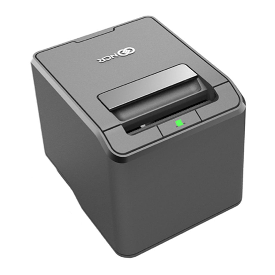
355mm or 14 inches per second, and sharp graphics in 16 levels of grayscale. The printer can be wall mounted, integrated with an NCR RealPOS terminal, or placed on the countertop as a front or top exiting receipt printer. It is flexible enough to meet the customer’s changing needs or space constraints. -
Page 20: Features And Options
NCR RealPOS 7199 Thermal Receipt Station Printer Features and Options The 7199 Thermal Receipt Station Printer comes with the proven features and functionality of the 7197 along with several new features and options that enhance the printer’s performance, serviceability, reliability, and versatility. - Page 21 NCR RealPOS 7199 Thermal Receipt Station Printer • PC Code Page 865 (Nordic) • PC Code Page 866 (Cyrillic) • PC Code Page 1252 (Windows Latin #1) • PC Code Page 1256 (Arabic) – Contextual • PC Code Page 1256 (Arabic) – Fixed •...
-
Page 22: Thermal Print Head
NCR RealPOS 7199 Thermal Receipt Station Printer Thermal Print Head The 7199 Thermal Receipt Station Printer uses a thermal print head for printing receipts. It is extremely fast and quiet. Because it uses heat to print directly on paper, there is no cassette or ribbon to change, eliminating soiled fingers and paper dust. -
Page 23: Ordering Paper And Supplies
856461 Red/Black 856458 Blue/Black To order thermal receipt paper, contact your sales representative or order from NCR at the following toll free number: Iconex Media Products Division Voice: 1(800)543-8130 (toll free), or local listing of Media Products sales office... -
Page 24: Other Supplies
NCR RealPOS 7199 Thermal Receipt Station Printer Other Supplies Contact your sales representative to order the supplies listed in the following table. Item Type Alias Number External Power Supply 75W External Power 7167-K511 Supply, No Power Cord 75W External Power... - Page 25 NCR RealPOS 7199 Thermal Receipt Station Printer Item Type Alias Number Cash Drawer Cable 1.8 meters 1639-K044 1639-K043 1639-K213 0.6 meter (Y-Cable) 1416-C372-0006 1639-K045 Narrow 58mm Width Release 1.0 7199-K058 Paper Guide Ethernet Cable 8–wire 1432-C046-0030 Integrated Terminal Filler 7607-K324...
-
Page 26: What Is In The Box
The following items are packed in the shipping box: • Printer enclosed in a plastic bag and foam pack These items may be ordered as options from NCR: • Communication cable (from host computer to printer) • Cash drawer cables These cables may be ordered from other equipment suppliers. -
Page 27: Repacking The Printer
NCR RealPOS 7199 Thermal Receipt Station Printer Repacking the Printer To repack the printer, follow these steps: 1. Place the printer in the plastic bag and in the foam pack. 2. Place the packed printer in the box. 3. Secure the box with packing tape. -
Page 28: Cleaning The Printer
NCR RealPOS 7199 Thermal Receipt Station Printer Cleaning the Printer Cleaning the Cabinet The external cabinet materials and finish are durable and resistant to these items: • Cleaning solutions • Lubricants • Fuels • Cooking oils • Ultraviolet light The 7199 Thermal Receipt Station Printer does not require a scheduled maintenance. -
Page 29: Choosing A Location
NCR RealPOS 7199 Thermal Receipt Station Printer Choosing a Location Normal Table Top The 7199 Thermal Receipt Station Printer takes up a relatively small counter space and may be set on or near the host computer. Make sure there is enough room to open the receipt cover to change the paper. - Page 30 NCR RealPOS 7199 Thermal Receipt Station Printer Print the following template to use as a guide for the wall screw position.
-
Page 31: Connecting The Cables
NCR RealPOS 7199 Thermal Receipt Station Printer Connecting the Cables There are three different types of cables that connect to the printer: • Power supply cable supplying power from the power supply • Communication cable (USB) connecting the printer to the host computer •... -
Page 32: Usb Cable Connection
NCR RealPOS 7199 Thermal Receipt Station Printer USB Cable Connection Note: If the power supply cable has a ferrite bead, follow the routing shown in the following image. -
Page 33: Different Types Of Y-Cable Routing Method
NCR RealPOS 7199 Thermal Receipt Station Printer Different types of Y–cable routing method The following cable part numbers can be used for the Y-cable: • 1432-C402-0040 • 1432-C086-0010 • 1432-C404-0040 • 1432-C328-0040 • 1432-C088-0010 • 1416-C881-0010 • 1416-C713-0010 • 1416-C640-0010... -
Page 34: Cable Connection (Option)
NCR RealPOS 7199 Thermal Receipt Station Printer RS–232 Cable Connection (Option) Note: If the RS–232 serial cable has a ferrite bead on one side, connect the side without the ferrite bead to the printer. - Page 35 NCR RealPOS 7199 Thermal Receipt Station Printer Note: If the power supply cable has a ferrite bead, route the cable under the communication connector and cash drawer cable, and then to the cable restraints. Do the same for the Ethernet Cable Connection.
-
Page 36: Ethernet Cable Connection (Option)
NCR RealPOS 7199 Thermal Receipt Station Printer Ethernet Cable Connection (Option) -
Page 37: Checking For Usb Support On The Host Computer
With the required hardware in place, the Windows POS Ready 2009 operating system natively supports plug–and–play USB with a built–in driver. Note: You need an Internet access to download the USB drivers from the NCR Web site: http://www5.ncr.com/support/support_drivers_patches.asp. -
Page 38: Interface Description
NCR RealPOS 7199 Thermal Receipt Station Printer Interface Description Human Interfaces • Top Cover/Printer Door—the printer does not print or operate if the cover is open. • Cover Open Latch—the Top Cover/Printer Door can be opened by lifting the latch. -
Page 39: Using The Printer
NCR RealPOS 7199 Thermal Receipt Station Printer Using the Printer To use the printer, follow these steps: 1. Connect the power supply to the printer and turn on the power source. The printer goes through a self–test routine to ensure everything is working properly, and then it “beeps.”... -
Page 40: Loading And Changing The Receipt Printer
NCR RealPOS 7199 Thermal Receipt Station Printer Loading and Changing the Receipt Printer Change the paper when either of the following two conditions occurs: • Amber LED blinks (slow): the paper is low. There are approximately 1 ½ to 7 ½ meters (5–25 feet) of paper remaining on the roll. - Page 41 NCR RealPOS 7199 Thermal Receipt Station Printer 2. Remove the used roll.
-
Page 42: Loading The Paper Roll
NCR RealPOS 7199 Thermal Receipt Station Printer Loading the Paper Roll To load the paper roll, follow these steps: Note: Tear off the end of the new roll so that the edge is loose. 1. Place the new roll in the bin with a little extra paper extending over the front. Make sure that the paper unrolls from the bottom of the roll. -
Page 43: Advancing The Paper
NCR RealPOS 7199 Thermal Receipt Station Printer 2. Close the receipt cover. 3. Remove the excess paper by tearing it against the tear–off blade. Advancing the Paper To advance the paper, follow these steps: 1. Press the Paper Feed button on the operator panel to advance the paper. The cover must be closed. -
Page 45: Chapter 2: Troubleshooting Problems
Troubleshooting Problems Chapter 2: Overview The 7199 Thermal Receipt Station Printer is a simple, generally trouble–free printer, but from time to time, minor problems may occur. The multi–colored LED lights provide associates with visual feedback for error correction. For some problems, the printer communicates the information to the host computer and relies on the application to indicate what the problem is. -
Page 46: Red Led Is Off Or Printer Will Not Print
2-28 Troubleshooting Problems Red LED is off or Printer Will Not Print Cause What to Do Where to Go Cables may Check all cable connections. Check that the Refer to not be host computer and power supply are both on Connecting the connected (the power supply is turned on by plugging it... -
Page 47: Amber Led Blinking (Fast)
Troubleshooting Problems 2-29 Amber LED Blinking (Fast) Cause What to Do Where to Go Receipt Change the paper now. Do not run a Refer to Loading paper is out transaction without paper as the data and Changing the may be lost. Receipt Printer page 22. - Page 48 2-30 Troubleshooting Problems Cause What to Do Where to Go Thermal The print head may overheat when Refer toPhysical print head printing in a room where the and Operating temperature temperature is above the recommended Environment is out of operating temperature or when printing page 130 for the range...
-
Page 49: Receipt Printing Is Light Or Spotty
Troubleshooting Problems 2-31 Receipt Printing is Light or Spotty Cause What to Do Where to Go Thermal Open the receipt cover and clean the Refer to Cleaning the print head thermal print head with cotton swabs Printer page 10. may be dirty and isopropyl alcohol. -
Page 50: Stuck Cutter Blade
Troubleshooting Problems Stuck Cutter Blade If a cutter blade is stuck in a fully extended position, do the following steps to fix it: 1. Open the front cover. To open the front cover, do the following: a. Unlatch the front cover by pulling on the holes located on both sides of the front cover. - Page 51 Troubleshooting Problems 2. Flip to open the top cover. the cutter blade is in the extended position. 3. Remove the jammed paper.
- Page 52 Troubleshooting Problems Note: Ensure that the paper is not at the paper exit area. 4. Close the top cover (A) and then the front cover (B). When the printer detects that both covers are closed, the moving blade automatically retracts the exposed blade back to the cutter module. Note: The printer does not operate if either the front cover or the top cover is not closed.
-
Page 53: Other Serious Problems
In addition to the service guide listed below, other service– related materials may be available. Contact your NCR–authorized service representative to obtain these documents. • NCR RealPOS 7199 Thermal Receipt Station Printer Parts Identification Manual (PIM) (BCC5–0000–5173) • NCR RealPOS 7199 Thermal Receipt Station Printer Service Guide (BCC5–0000–5174) -
Page 55: Chapter 3: Service Level Troubleshooting
Service Level Troubleshooting Chapter 3: Diagnostics Overview The 7199 Thermal Receipt Station Printer performs four types of diagnostic tests to help troubleshoot problems and to change the printer configuration. Each of these is described in detail in the sections that follow. •... -
Page 56: Startup (Level 0) Diagnostics
3-38 Service Level Troubleshooting Startup (Level 0) Diagnostics The printer automatically performs startup diagnostics during the startup cycle when power is supplied or when the printer goes online. Startup diagnostics comprise the following actions: 1. Power off the printer. 2. Perform CRC check of the firmware ROM, read external RAM. Note: Failure causes startup diagnostics to stop. -
Page 57: Printer Configuration (Level 1)
Service Level Troubleshooting 3-39 Printer Configuration (Level 1) Level 1 diagnostics (setup mode) provides the functionality to change the settings for various printer functions. Take note of the following information when changing the settings: • The default options are set at the factory and are stored in the history non–volatile memory. -
Page 58: Runtime (Level 2) Diagnostics
3-40 Service Level Troubleshooting Runtime (Level 2) Diagnostics Runtime diagnostics occur during normal printer operation. When the following conditions occur, the printer automatically turns off the appropriate motors and disables printing to prevent damage: • Paper out • Cover open •... -
Page 59: Configuring The Printer
Service Level Troubleshooting 3-41 Configuring the Printer Use the Configuration Menu to select functions or change various settings as indicated in the next sections. The Configuration Menu prints instructions and setting options interactively as the user goes through the configuration process. Caution: Be extremely careful in changing any of the printer settings to avoid changing settings that might affect the performance of the printer. -
Page 60: Software Or Hardware Configuration
3-42 Service Level Troubleshooting Software or hardware configuration To configure the software or hardware, follow these steps: 1. Open the Top Cover/Printer Door, and then check if the printer has paper. 2. Insert a paper roll if no paper is found. 3. - Page 61 Service Level Troubleshooting 3-43 Printer Configuration form indicates the printer individual information and configurations.
-
Page 62: Installing The Usb Virtual Com Port Driver For Printer
3-44 Service Level Troubleshooting Installing the USB Virtual COM Port Driver for Printer Windows POS Ready 7 To install the USB Virtual COM Port Driver for printer on a Windows POS Ready 7 system, follow these steps: 1. The printer beeps when it is plugged in to show the USB device is recognized. The Driver Software Installation window is displayed. - Page 63 Service Level Troubleshooting 3-45 2. Select Yes. The following window is displayed. 3. Open Device Manager, and then select Receipt (EPiC Interface). 4. Select the Update Driver Software button.
- Page 64 3-46 Service Level Troubleshooting 5. Select Browse my computer for driver software. 6. Select Browse, and then select the Edgeport Driver folder.
- Page 65 Service Level Troubleshooting 3-47 7. Select Next. The system starts installing the printer driver.
- Page 66 3-48 Service Level Troubleshooting Windows 8 To install the USB Virtual COM port driver for printers on a Windows 8 system, follow these steps: 1. The printer beeps when it is plugged in to show the USB device is recognized. Device Setup window displays that the Installing Receipt (EPiC Interface) process is ongoing.
- Page 67 Service Level Troubleshooting 3-49 3. Select the Update Driver Software button.
- Page 68 3-50 Service Level Troubleshooting 4. Select Browse my computer for driver software. 5. Select Browse, and then select the Edgeport Driver folder.
- Page 69 Service Level Troubleshooting 3-51 6. Select Next.
- Page 70 3-52 Service Level Troubleshooting The system starts installing the USB Virtual COM port driver for printers.
- Page 71 Service Level Troubleshooting 3-53 When the installation is complete, the following window is displayed.
- Page 72 3-54 Service Level Troubleshooting Windows 10 To install the USB Virtual COM Port Driver for Printer on a Windows 8 system, follow these steps: 1. The printer beeps when it is plugged in to show the USB device is recognized. The Device Setup window displays that the Installing Receipt (EPiC Interface) process is ongoing.
- Page 73 Service Level Troubleshooting 3-55 4. Select Browse my computer for driver software. 5. Select Browse, and then select the Edgeport Driver folder. 6. Select Next.
- Page 74 3-56 Service Level Troubleshooting The system starts installing the printer driver. When the installation is complete, the following window is displayed.
-
Page 75: Verifying The Installation
1. Open the Device Manager window. 2. Make sure that the NCR 7197 Receipt Printer and the EPIC Port are installed. Note: The NCR 7197 Receipt Printer is the defined USB VID/PID (Vendor ID/Product ID) of the NCR Single Station printers (7197, 7198, and 7199). - Page 76 3-58 Service Level Troubleshooting 3. Open the Edgeport utility and make sure the Port is assigned.
-
Page 77: Windows 8
To verify the installation of the driver on a Windows 8 system, follow these steps: 1. Open the Device Manager window. 2. Make sure that the NCR 7197 Receipt Printer and the EPIC Port are installed. Note: The NCR 7197 Receipt Printer is the defined USB VID/PID (Vendor ID/Product ID) of the NCR Single Station printers (7197, 7198, and 7199). - Page 78 3-60 Service Level Troubleshooting 3. Open the Edgeport utility and make sure the Port is assigned.
-
Page 79: Windows 10
To verify the installation of the driver on a Windows 10 system, follow these steps: 1. Open the Device Manager window. 2. Make sure that the NCR 7197 Receipt Printer and the EPIC Port are installed. Note: The NCR 7197 Receipt Printer is the defined USB VID/PID (Vendor ID/Product ID) of the NCR Single Station printers (7197, 7198, and 7199). - Page 80 3-62 Service Level Troubleshooting 3. Open the Edgeport utility and make sure the Port is assigned.
-
Page 81: Uninstalling The Drivers
Service Level Troubleshooting 3-63 Uninstalling the Drivers Windows POS Ready 7 To uninstall the printer driver on a Windows POS Ready 7 system, follow these steps: 1. Open the Edgeport utility. 2. Select the Advanced tab. 3. Select the Uninstall button, and then follow the on–screen instructions. The following window is displayed. - Page 82 3-64 Service Level Troubleshooting 4. Select Yes. The system uninstalls the driver, and then displays the following window. 5. Select Yes to completely uninstall the driver and to restart the PC.
-
Page 83: Windows 8
Service Level Troubleshooting 3-65 Windows 8 To uninstall the printer driver on a Windows 8 system, follow these steps: 1. Open the Edgeport utility. 2. Select the Advanced tab. 3. Select the Uninstall button, and then follow the on–screen instructions. The following window is displayed. - Page 84 3-66 Service Level Troubleshooting 4. Select Yes. The system uninstalls the driver, and then displays the following window. 5. Select Yes to completely uninstall the driver and to restart the PC.
-
Page 85: Windows 10
Service Level Troubleshooting 3-67 Windows 10 To uninstall the printer driver on a Windows 8 system, follow these steps: 1. Open the Edgeport utility. 2. Select the Advanced tab. 3. Select the Uninstall button, and then follow the on–screen instructions. The following window is displayed. - Page 86 3-68 Service Level Troubleshooting The system uninstalls the driver, and then displays the following window. 5. Select Yes to completely uninstall the driver and to restart the PC.
-
Page 87: Configuring Serial Port Number Assignments
You can check the assigned serial port by clicking the General tab in the Edgeport utility. You’ll see an entry for the NCR printer. Expand the list to see which serial port has been assigned to the printer. -
Page 88: Communication Interface Modes
3-70 Service Level Troubleshooting Communication Interface Modes The Configuration Menu gives the user the option of setting the printer to use a USB communication. RS–232C Interface Settings [Standard Model] If the user sets the printer to use an RS–232C serial interface, the Configuration Menu can be used to set the following RS–232C specific settings: •... -
Page 89: Usb Interface Settings [Standard Model]
Service Level Troubleshooting 3-71 USB Interface Settings [Standard Model] USB Interface setting can be changed by selecting USB Type in the Hardware menu. ** USB Type ION (EpiC) –> 1 Click NonION (NHPI) * –> 2 Clicks NonION (PRTR) –> 3 Clicks Enter code, then hold Button DOWN. -
Page 90: Ethernet Interface Settings [Option]
3-72 Service Level Troubleshooting Ethernet Interface Settings [Option] Press the Paper Feed button for the communications settings you want. - Page 91 Service Level Troubleshooting 3-73...
-
Page 92: Save Parameters
3-74 Service Level Troubleshooting Save Parameters This function allows to save the selected communication settings or return to the communication settings to select additional options. Press the Paper Feed button for the option you want. Emulation/Software Options Receipt Synchronization This function makes it possible for the user to select whether to enable or to disable receipt synchronization printing. -
Page 93: Save Parameters
Service Level Troubleshooting 3-75 Press the Paper Feed button for the receipt synchronization option you want. Save Parameters This function allows to save the selected communication settings or to return to the communication settings to select additional options. Press the Paper Feed button for the option you want. Default Lines per Inch This function allows the user to set the default lines per inch printed by the thermal printer to 6, 7.52, or 8.13. -
Page 94: Carriage Return Usage
3-76 Service Level Troubleshooting Carriage Return Usage This function allows the printer to ignore or use the Carriage Return (hexadecimal 0D) command depending on the application. Some applications expect the command to be ignored while others use the command as a print command. Press the Paper Feed button for the carriage return usage you want. -
Page 95: Set Font Type Option
Service Level Troubleshooting 3-77 Set Font Type option Set Font Type using the Emulation sub–menu. Caution: Be extremely careful in changing any of the printer settings to avoid inadvertently changing other settings that might affect the performance of the printer. Press the Paper Feed button for the option you want to choose. -
Page 96: Set 48 Character Mode
3-78 Service Level Troubleshooting Set 48 CHARACTER MODE This option is to set 48 Character printing. The selections are enable or disable. The end result is to print 48 characters in one line. Set PDF417 MAX COLUMN PRINT? This function makes it possible for the user to select the print columns for the PDF417 bar code printing. -
Page 97: Set Auto Reset Option
Service Level Troubleshooting 3-79 Set Auto Reset option Set Auto Reset using the configuration menu. Answer No to the questions printed on the receipt until you come to the instructions for Auto Reset. Caution: Be extremely careful in changing any of the printer settings to avoid inadvertently changing other settings that might affect the performance of the printer. -
Page 98: Hardware Options
3-80 Service Level Troubleshooting Hardware Options Set USB Type Set the USB type using the configuration menu. Select Hardware Options in the Configuration Menu. Caution: Be extremely careful in changing any of the printer settings to avoid inadvertently changing other settings that might affect the performance of the printer. Press the Paper Feed button for the USB type you want. -
Page 99: Set Print Mode
Failure to observe this rule may result in a printer service call or voiding of the printer warranty. Consult your NCR technical support specialist if you have any questions. Press the Paper Feed button for the print density you want. -
Page 100: Power Supply
3-82 Service Level Troubleshooting If 1 click was selected, it is printed as follows. Power Supply This function allows the user to set the maximum power for the printer to the below modes available. Press the Paper Feed button for the option you want. -
Page 101: Set Standby Mode
Service Level Troubleshooting 3-83 Set Standby Mode Enable or disable the Standby Mode using the configuration menu. If the standby mode is enabled, the printer shifts to the standby mode in order to save the power consumption in the idle mode when the printer is in the idle mode. Printer will exit from standby mode to normal mode in below criteria: •... -
Page 102: Set Power Off Mode
3-84 Service Level Troubleshooting Set Power Off Mode Set the Shift Time to Power Off using the configuration menu. If the printer is in standby mode for the time that is defined by this setting, printer automatically power off. Once enter power off mode, all LED are turned off. If feed key is pressed, printer exit from power off mode and enter normal mode. -
Page 103: Paper Width
Service Level Troubleshooting 3-85 Paper Width This function allows the user to set the default paper width for the receipt thermal printer to 58mm or 80mm wide. Press the Paper Feed button for the paper width option you want. Set Paper Low Detection Paper Low Sensor makes it possible to enable or disable the paper low sensor for particular printer configurations. -
Page 104: Set Color Paper Option
3-86 Service Level Troubleshooting Set Color Paper Option This function allows the user to set the color paper option to Monochrome or Color Paper. Press the Paper Feed button for the option you want. Set Buzzer Tone This function allows the user to set the Buzzer Tone to Low, Middle and High. Press the Paper Feed button for the option you want. -
Page 105: Set Power Led Control
Service Level Troubleshooting 3-87 Set Power LED Control Set the power LED control using the configuration menu. Answer No to the questions printed on the receipt until you come to the instructions for power LED control. Caution: Be extremely careful in changing any of the printer settings to avoid inadvertently changing other settings that might affect the performance of the printer. -
Page 106: Default Code Page
3-88 Service Level Troubleshooting Default Code Page This function makes it possible to select the default code page. These are the code pages available for printing: • Code page 437 (US English) • Code page 850 (Multilingual) • Code page 852 (Slavic) •... - Page 107 Service Level Troubleshooting 3-89 To set the Code Page, emulation mode should be selected: 1. To enter into emulation mode from the main menu, press the Paper Feed button twice as short click and hold the button until a beep sound is generated. The following submenu will be displayed.
- Page 108 3-90 Service Level Troubleshooting...
-
Page 109: Runtime (Level 2) Diagnostics
Service Level Troubleshooting 3-91 Runtime (Level 2) Diagnostics Runtime diagnostics occur during normal printer operation. When the following conditions occur, the printer automatically turns off the appropriate motors and disables printing to prevent damage: • Paper out • Cover open •... - Page 110 3-92 Service Level Troubleshooting In “User Mode” of Printer Status LED, a system controls LED by “LED Control Request”, LED pattern and the indication timing are specified by a system. Errors COLOR Bezel LED Memory Error 1 Blink Pause 5 seconds Thermal Head Disconnected 2 Blink Pause 5 seconds Thermal Head Abnormal...
-
Page 111: Pc Board Connector Locations And Designations
Service Level Troubleshooting 3-93 PC Board Connector Locations and Designations Driver Board... -
Page 112: Fuse Location And Information
3-94 Service Level Troubleshooting Fuse Location and Information Refer to the following table for more information: Specifications Location Part Description 25H3000G (skygate) or equivalent 125V / 3A 25H5000G (skygate) or equivalent 125V / 5A... -
Page 113: Chapter 4: Communication
Communication Chapter 4: Communication Overview In order for a receipt to be printed, a program must be in place that translates the data from the host computer into a language that the printer can understand. This program must tell the printer exactly how to print each character. This chapter describes how to create such a program or modify an existing one. -
Page 114: Rs-232C Interface (Option)
4-96 Communication RS-232C Interface (Option) The RS-232C version of the 7199 printer offers the standard options which are selectable in the Diagnostic mode. For more information, refer to Communication Interface Modes page 70. Print Speed and Timing The fast speed of the printer requires the application to send data to the printer at least as fast as it is printed. -
Page 115: Rs-232C Technical Specifications
Communication 4-97 The following table shows that with no delay between lines, the transmit time is much less than the print time, allowing the printer to print at full speed. Transmit Time: Transmit Time: (19.2 Print Char./Line Lines/Receipt (9600 Baud) K Baud) Time 0.4 seconds... -
Page 116: Ethernet Interface (Option)
4-98 Communication Ethernet Interface (Option) The Ethernet interface uses either 10BASE–t, 100BASE–TX protocol. The Ethernet version of the 7199 printer offers the web configuration, which configure the Ethernet settings through a Web browser. For more information, refer to the Communication Interface Modes on page 70. -
Page 117: Snmp
Communication 4-99 SNMP SNMP is used by the SNMP manager to acquire the printer information and status from SNMP agent (Printer). SNMP version SNMP v1 (RFC1157) compliant Transport protocol UDP/IP MIB support Part of MIB-II (RFC1213) Part of HOST Resource Part of Printer MIB PDU support Get Request Get Next Request Get Response... -
Page 118: Http
4-100 Communication HTTP HTTP is used to configure the network setting by WEB Provision. HTTP version V1.1 Transport protocol TCP/IP Items to be able to configure IP address Subnet mask Default Gateway DHCP DHCP address TCP max. connection Ethernet Physical LAN Speed LAN Real Time Command Protocol Link Down Timeout TCP idle Timeout TCP Port number... -
Page 119: Tcp Socket Communication
Communication 4-101 TCP Socket Communication The communication procedure is designed as follows. The TCP socket is used to send commands and data related to printing. And, it is also used to send and receive the batch status commands and its statuses. When "Ethernet RTC Protocol"... -
Page 120: Udp Socket Communication
4-102 Communication UDP Socket Communication The UDP socket is used by sending and receiving of Real Time Command. This is effective in UDP port 3000 when "Ethernet RTC Protocol" setting is UDP. 1. Client PC connects to the UDP socket via the defined port number of the printer. 2. -
Page 121: Connector
Communication 4-103 Connector This section discusses the following NCR 7199 cable connectors: • Power Cable Connector • USB Cable Connector • RS–232C Connector • Ethernet Connector • Cash Drawer Connector Power Cable Connector The control cards received 24VDC +–10% power via a 3–pin Mini–DIN plug, which mates with an integral shielded cable from the power supply unit. -
Page 122: Usb Cable Connector
4-104 Communication USB Cable Connector USB I/F is mounted on main card as default. There are 2 ports. The first port is for the HOST function with Type A connector, and the second port is for the Device function with Type B connector. It does not support USB host port and device port at the same time. -
Page 123: Rs-232C Communication Connector Pin Assignments
Communication 4-105 RS–232C Communication Connector Pin Assignments The serial I/F connector is 9pin D–SUB Male type connector with the following pin assignments:... -
Page 124: Ethernet Connector
4-106 Communication Ethernet Connector The following specification is for the model equipped with Ethernet connection. Standard Fully integrated IEEE 802.3/802.3u–100 Base–TX/10 BASE–T Physical Layer Speed Auto Negotiation: 10Mbps/100Mbps, Full/Half Duplex Connector Pin Assignment The Ethernet I/F connector is an 8P8C modular connector (usually called RJ45) with the following pin assignments: Pin Position Signal Description TX–... -
Page 125: Cash Drawer Connector And Pin Assignments
Communication 4-107 Cash Drawer Connector and Pin Assignments The Cash drawer connector is located at the rear of the printer. The Cash drawer connector is a 6–pin modular type connector with the following pin assignments:... - Page 126 4-108...
-
Page 127: Chapter 5: Command
For more information and for the list of commands, refer to the NCR RealPOS 7199 Thermal Receipt Station Printer Programmer's Guide (BCC5-0000-5170). - Page 128 5-110...
-
Page 129: Chapter 6: Reflashing The Printer Firmware
Flash Utility Information The following instructions provide information on how to use the Flash Utilities provided for the NCR 7167 series, 7168 series, 7197 series, 7198 series, 740x-K59x series, 734X series, 7649–F301, and 7199 printers. These instructions cover the utilities provided for Windows GUI and Windows Command Line. -
Page 130: Printer Languages Cross-Reference
The following items need to be noted: • The noted font files are included on LPIN A370-0050-0000 or are available from the NCR web site under Retail Solution Specific Printer Firmware. • The asterisk (*) denotes that the printer is preloaded with these fonts from the factory. -
Page 131: Windows Command Line Firmware Update Utility
Reflashing the Printer Firmware 6-113 Windows Command Line Firmware Update Utility The Windows Command Line version of the Flash Utility is provided to allow batch mode of operation in a Windows XP environment. If you issue a call to TseFlash.com with no parameter, you will get the following output that explains the parameters. - Page 132 6-114 Reflashing the Printer Firmware /WIFIWireless Interface. /HID Only for K8 printers. /NHPI Only for 7199 printers. /PRTR Only for 7199 printers. [parameter] --> Selections for interface parameter (Only for RS232 and Ethernet interface): For RS232 Only: Please key in the Baud Rate, Parity and Stop - Baud Rate Selection: /[115200] | [57600] | [38400] | [19200] | [9600] - Parity Selection:...
- Page 133 On the host terminal or PC running Windows, execute the utility TSEFlash.ex*** to start the program. A window similar to the example below will appear on the screen. Note: The flash utility shown is for demonstration purposes only. Visit NCR Support Site for the latest release.
- Page 134 6-116...
-
Page 135: Chapter 7: Configuration Network
Configuration Network Chapter 7: Overview The printer provides the Ethernet Network Configuration page in a Web page (respondent HTTP/1.0 and 1.1) The Configuration page can be accessed by connecting the Host PC to the printer via the network and inputting the printer's IP address in the Web browser address bar. Example: http://192.168.1.1/main.html) in the Web browser The Host PC needs to be set with the correct network configuration (IP address, Subnet mask address, and so forth) to connect to the printer. -
Page 136: Display Format Of Configuration Setting Page
7-118 Configuration Network Display Format of Configuration Setting Page This section discusses the display format of the Ethernet Network Configuration page. Top Page On the Top page, the Show Configuration button is displayed. when it is selected, the Ethernet Configuration setting page is displayed with the current configuration. -
Page 137: Ethernet Configuration Setting Page
Configuration Network 7-119 Ethernet Configuration Setting Page On Ethernet Configuration setting page, users can view or change the Ethernet configuration. To change the Ethernet configuration, do the following: 1. Change the values by doing any of the following: • Enter a value in the corresponding text box. •... - Page 138 7-120 Configuration Network...
-
Page 139: Save Configuration Message Page
Configuration Network 7-121 Save Configuration Message Page On the Save Configuration Message page, users are informed that the new Ethernet configuration is successfully saved. To apply the new configuration to the printer, select RESET PRINTER. Error Message Page On the Error Message page, users are informed that the new Ethernet configuration is not saved. -
Page 140: Tcp/Ip Setting
7-122 Configuration Network TCP/IP Setting This section discusses configuration parameters and default values for the TCP/IP setting. IP setting Items Default value Detail 192.168.1.1 Set Printer IP Address. This IP Address is effective Address when Get IP Address is Manual. 255.255.255.0 Subnet Set Printer Subnet Mask. -
Page 141: Ip Address Automatic Acquisition
Configuration Network 7-123 IP Address Automatic Acquisition When "DHCP" is enabled, the printer automatically gets the IP address, the Subnet Mask and the Default Gateway from a DHCP server. If the printer fails to automatically get the IP address, it uses the same IP address as the Manual mode. The DHCP allocated IP address can be seen on the Diagnostics Form of the connected printer. -
Page 142: Other Ethernet Setting
7-124 Configuration Network Other Ethernet Setting Default Items Detail value MAC Address ____ Show MAC Address of the printer Ethernet interface. This is the unique value for each Ethernet interface and show only. Physical Layer Auto Select connection Speed and Duplex. (Auto / 10Mbps Half/10 Mbps Full / 100Mbps Half/ 100Mbps Full) -
Page 143: Snmp Setting
Configuration Network 7-125 SNMP Setting This section discusses configuration parameters and default values for the SNMP setting. SNMP Community Setting Items Default value Detail Read Only public Show SNMP community read only name. Maximum length is 16 characters. Read/Write Set SNMP community read-write name. Maximum length is 16 characters. -
Page 144: Snmp Ip Trap2 Setting
7-126 Configuration Network SNMP IP Trap2 Setting Default Items Detail value TRAP Disable Select whether SNMP TRAP is “Enable” or “Disable”. 0.0.0.0 Address Set address of host that receives SNMP TRAP. Community Set SNMP TRAP community name. Name Maximum length is 16 characters. -
Page 145: Appendix A: Printer Specifications
Printer Specifications Appendix A: Printing Specifications Print head • Fixed • 576 Print Elements • Direct Thermal • Fixed Head • Line of Dots Character Cell Standard: 13 x 24 Dots Compressed: 10 x 24 Dots Character Size 0.0525-inch wide by 0.092-inch high Character Spacing 15.25 characters per inch (horizontal) Character Pitch 15.6 characters per inch (Standard) - Page 146 A-128 Printer Specifications Line Spacing 7.52 lines per inch (default) 8.47, 8.13, 7.81, 7.25, 7.00, 5.98 lines per inch and variable lines per inch. Print Zone 2.83 inches maximum Noise 57 dBA Sound Pressure (ISO 7779) Paper reduction, Power reduction Other No Reverse Paper Feed...
-
Page 147: Power Requirements
The external power supply must provide a +24V line of power to the printer. Surge protection must be provided. • When NCR 75W external power supply is used, select (NCR 75W Ext Pwr) mode. • When NCR 60W external power supply is used, select (NCR 60W Ext Pwr) mode. -
Page 148: Physical And Operating Environment
A-130 Printer Specifications Physical and Operating Environment Temperature and Humidity Temperature Humidity Operating 5 to 50°C (41 to 122°F) 5% to 90% Storage –10 to 55°C (14 to 131°F) 10% to 90% Transit –40 to 60°C (–40 to 140°F) 5% to 95% Condensation Condensation may occur when the printer is moved from cold to warm areas after shipment. -
Page 149: Appendix B: Re-Flashing The Printer Firmware
Re–flashing the Printer Firmware Appendix B: Flash Utility is used to flash the firmware and font files to the printer. Note: For the detailed procedure, refer to the NCR Printer Flash Utility Owners Guide from the NCR web site, http://www5.ncr.com/support/support_drivers_ patches.asp?Class=External\Peripherals\Printer\FlashUtility\display. -
Page 151: Appendix C: Lean Receipt Utility
Lean Receipt Utility Appendix C: Lean Receipt Utility is used to set the printer ECO setting from the utility. For detailed procedure, refer to the Lean Receipt utility user manual from the NCR web site: http://www5.ncr.com/support/support_drivers_ patches.asp?Class=External\Peripherals\Printer\LeanReceiptUtility\display. -
Page 153: Appendix D: Print Characteristics
Print Characteristics Appendix D: Character Size This section shows the dot pattern for characters printed on the receipt station. Receipt Station The following two illustrations show the dot patterns of sample characters for standard pitch (15.6 CPI) and compressed pitch (20.3 CPI). Note: Compressed pitch uses fewer dots horizontally than standard pitch. -
Page 154: Print Zones
D-136 Print Characteristics Print Zones This section shows the printable area for the receipt station. Receipt Station For 80-mm Paper The receipt station centers characters (standard pitch and compressed pitch) and graphics on a receipt with a width of 27 dots or 80 mm (3.15 inches). •... - Page 155 Print Characteristics D-137 The minimum print line height is 24 dots for characters and 24 dots for graphics. The standard print line height is 27 dots or 3.38 mm (0.133 inches) for characters (with three extra dot rows). Refer to the illustration below (not to scale).
-
Page 157: Appendix E: Thai Code
Thai Code Page Function Appendix E: Outline 7199 RealPOS Thermal Receipt Station Printer supports printing of Thai characters. Code Page 874 (Thai) supports Thai character, but, some characters of them define only a part of one character. Actual Thai character is made up of a combination of some characters (maximum 4 characters in CP 874) for one Thai character. -
Page 158: Validate Thai Code Page Function
E-140 Thai Code Page Function Validate Thai Code Page Function The Thai code page function is validated when the following conditions are selected. • Online mode • Asian Mode = OFF • Code Page = 874 Thai Character Configuration The character cell of Thai character is made up of a maximum 4 parts—Top level, Above level, Base line and Below level.) •... - Page 159 Thai Code Page Function E-141 Below mentions about each character type. Base line characters • Base line characters are the characters encircled in red, purple, and pink. • The characters encircled in purple will not have below level characters, but they are rarely used.
- Page 160 E-142 Thai Code Page Function Thai Character Data Procedure Thai character data string uses the following format: Base character, <Below character >, <Above character>, <Top character>, Base character, …… The printer checks whether the received character is the Base character. If the Top, Above, Below characters are sent before the Base character, these characters are ignored.
- Page 161 Thai Code Page Function E-143 The line pitch is changed by below commands because the code page is changed. ESC R Select international character set. ESC t Select character code table. Note: Same as ESC R. ESC % Set/cancel the user–defined character set. ESC L Set page mode.
-
Page 163: Appendix F: Arabic Font Support
Arabic Font Support Appendix F: Outline 7199 RealPOS Thermal Receipt Station supports several features of Arabic font, such as the following: • Contextual forms • Word ligatures • Reverse the Arabic strings These features can be achieved based on the proportional font and they are available according to the following conditions: •... -
Page 164: Reverse The Arabic Strings
F-146 Arabic Font Support Reverse the Arabic strings Arabic writing is from right to left by aligning right margin. The data received by the printer will reverse the arabic string and print as per the Arabic format, which is right to left. -
Page 165: Proportional Font Conversion Handling Of Arabic
Due to the features of Arabic font, there are several limitations in terms of the character attributes. For more information on the command description, refer to the NCR RealPOS 7199 Thermal Receipt Station Printer Programmer's Guide (BCC5-0000-5170). Please see the command description of Print Characteristic Commands in detail. - Page 166 F-148 Arabic Font Support Command Command name Remarks ESC ? Cancel User-Defined Characters ESC E Select or Cancel Emphasized Mode ESC G Select Double Strike ESC H Cancel Double Strike ESC I Select or Cancel Italic Print ESC V Select or Cancel 90 Degrees Clockwise Rotated Print ESC { Select or Cancel Upside Down Printing Mode...
-
Page 167: Horizontal Positioning Commands
Arabic Font Support F-149 Horizontal Positioning Commands Ex) HT Horizontal Tab (6,12,18) -
Page 168: Invalid Command (Sample)
F-150 Arabic Font Support Invalid command (sample) Ex) ESC DC2 Select 90 Degree Counter-Clockwise Rotated Print... -
Page 169: Invalid Command In Middle Of The Line (Example)
Arabic Font Support F-151 Invalid command in middle of the line (example) It is invalid for the middle of the line . Ex) DC2 Select Double-Wide Characters... -
Page 170: Printing Layout (Over The Area)
F-152 Arabic Font Support Printing Layout (Over the Area) If the Arabic character line exceeds printable area, it will be printed as bellows. -
Page 171: Character Sets
Arabic Font Support F-153 Character Sets The following pages show the character sets. • PC Code Page 437 (US) • PC Code Page 850 (Multilingual) • PC Code Page 852 (Slavic) • PC Code Page 860 (Portuguese) • PC Code Page 862 (Hebrew) •... - Page 172 F-154 Arabic Font Support Code Page 950 Code Page 437, 850, 852 and 858...
- Page 173 Arabic Font Support F-155 Code Page 860, 862, 863 and 864...
- Page 174 F-156 Arabic Font Support Code Page 865, 866, 874 and 1252...
- Page 175 Arabic Font Support F-157 Code Page 1256 and Katakana...
- Page 176 F-158 Arabic Font Support Code Page 932...
- Page 177 Arabic Font Support F-159 Code Page 932 (continuation)
- Page 178 F-160 Arabic Font Support Code Page 932 (continuation)
- Page 179 Arabic Font Support F-161 Code Page 932 (continuation)
- Page 180 F-162 Arabic Font Support Code Page 932 (continuation)
- Page 181 Arabic Font Support F-163 Code Page 932 (continuation)
- Page 182 F-164 Arabic Font Support Code Page 932 (continuation)
- Page 183 Arabic Font Support F-165 Code Page 932 (continuation)
- Page 184 F-166 Arabic Font Support Code Page 932 (continuation)
- Page 185 Arabic Font Support F-167 Code Page 936 Simple Chinese...
- Page 186 F-168 Arabic Font Support Code Page 936 Simple Chinese (Continuation)
- Page 187 Arabic Font Support F-169 Code Page 936 Simple Chinese (Continuation)
- Page 188 F-170 Arabic Font Support Code Page 936 Simple Chinese (Continuation)
- Page 189 Arabic Font Support F-171 Code Page 936 Simple Chinese (Continuation)
- Page 190 F-172 Arabic Font Support Code Page 936 Simple Chinese (Continuation)
- Page 191 Arabic Font Support F-173 Code Page 936 Simple Chinese (Continuation)
- Page 192 F-174 Arabic Font Support Code Page 936 Simple Chinese (Continuation)
- Page 193 Arabic Font Support F-175 Code Page 936 Simple Chinese (Continuation)
- Page 194 F-176 Arabic Font Support Code Page 936 Simple Chinese (Continuation)
- Page 195 Arabic Font Support F-177 Code Page 936 Simple Chinese (Continuation)
- Page 196 F-178 Arabic Font Support Code Page 936 Simple Chinese (Continuation)
- Page 197 Arabic Font Support F-179 Code Page 949 Korean...
- Page 198 F-180 Arabic Font Support Code Page 949 Korean (Continuation)
- Page 199 Arabic Font Support F-181 Code Page 949 Korean (Continuation)
- Page 200 F-182 Arabic Font Support Code Page 949 Korean (Continuation)
- Page 201 Arabic Font Support F-183 Code Page 949 Korean (Continuation)
- Page 202 F-184 Arabic Font Support Code Page 949 Korean (Continuation)
- Page 203 Arabic Font Support F-185 Code Page 949 Korean (Continuation)
- Page 204 F-186 Arabic Font Support Code Page 949 Korean (Continuation)
- Page 205 Arabic Font Support F-187 Code Page 949 Korean (Continuation)
- Page 206 F-188 Arabic Font Support Code Page 949 Korean (Continuation)
- Page 207 Arabic Font Support F-189 Code Page 949 Korean (Continuation)
- Page 208 F-190 Arabic Font Support Code Page 949 Korean (Continuation)
- Page 209 Arabic Font Support F-191 Code Page 949 Korean (Continuation)
- Page 210 F-192 Arabic Font Support Code Page 949 Korean (Continuation)
- Page 211 Arabic Font Support F-193 Code Page 949 Korean (Continuation)
- Page 212 F-194 Arabic Font Support Code Page 949 Korean (Continuation)
- Page 213 Arabic Font Support F-195 Code Page 950 Traditional Chinese...
- Page 214 F-196 Arabic Font Support Code Page 950 Traditional Chinese (Continuation)
- Page 215 Arabic Font Support F-197 Code Page 950 Traditional Chinese (Continuation)
- Page 216 F-198 Arabic Font Support Code Page 950 Traditional Chinese (Continuation)
- Page 217 Arabic Font Support F-199 Code Page 950 Traditional Chinese (Continuation)
- Page 218 F-200 Arabic Font Support Code Page 950 Traditional Chinese (Continuation)
- Page 219 Arabic Font Support F-201 Code Page 950 Traditional Chinese (Continuation)
- Page 220 F-202 Arabic Font Support Code Page 950 Traditional Chinese (Continuation)
- Page 221 Arabic Font Support F-203 Code Page 950 Traditional Chinese (Continuation)
- Page 222 F-204 Arabic Font Support Code Page 950 Traditional Chinese (Continuation)
- Page 223 Arabic Font Support F-205 Code Page 950 Traditional Chinese (Continuation)
Need help?
Do you have a question about the RealPOS 7199 and is the answer not in the manual?
Questions and answers