
Related Manuals for Compuprint X03


Summary of Contents for Compuprint X03
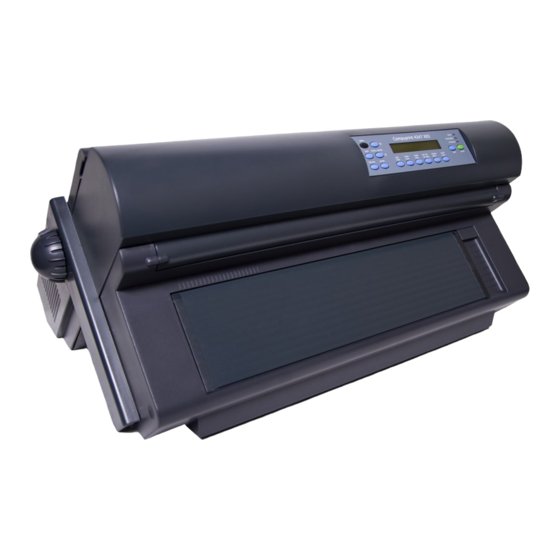
- Page 1 Compuprint 4247 Serial Matrix Printers Compuprint 4247 Model X03 Printer: User’s Guide MAN10296.00.00...
- Page 2 Before using this information and the product it supports, read the information in “Notices” on page 181. First edition (October 2011) This edition applies to the Compuprint 4247 X03 printer and to all subsequent releases and modifications until otherwise indicated in new edition.
-
Page 3: Table Of Contents
Contents Figures ....vii ENTER . . 31 RETURN . . 32 PARK/PATH . . 32 Tables ....ix LINE FEED . - Page 4 Media Size Priority . . 63 Continuous Forms Linking . . 104 Bar Code Mode . . 64 Form Feed Mode . . 105 Graphics Mode . . 65 Controlling tear off operations. . 106 Alarm control . 66 Using automatic eject to control forms eject . .
- Page 5 . 171 Cleaning the printer . . 149 Appendix B. 4247 Model X03 - Chapter 19. Problem solving ..151 Configuration Menu..173 Using status code and problem listings .
- Page 6 User’s Guide...
-
Page 7: Figures
Figures Printer Parts: Front and Rear View . Adjusting the right sprocket . . 19 Contents of Shipping Container . Closing the Push tractors cover. . . 19 Removing the shipping locks from the printer. Opening the tractor area cover. . . - Page 8 viii User’s Guide...
-
Page 9: Tables
Tables Configuration Storage Category . . 41 Forms do not feed past printhead . . 156 Attachment Category . . 41 Forms do not stack correctly . 156 IPDS Configuration Category . 41 Characters off registration . . 157 ASCII Configuration . - Page 10 User’s Guide...
-
Page 11: Safety And Environmental Notices
Safety and environmental notices Safety notices There are two levels of safety notices: Danger and Cautions. Danger hazard level The word Danger indicates the presence of a hazard that has the potential of causing death or serious personal injury. Most DANGER notices are numbered <1-1>, <1-2>, and so forth where they appear in the text of this manual. -
Page 12: Safety Precautions
Safety precautions Electrical safety This printer is inspected and listed by recognized national testing laboratories, such as Underwriters Laboratories, Inc. (UL) in the U.S.A. and Canadian Standards Association (CSA) in Canada. Listing of a product by a national testing laboratory indicates that the product is designed and manufactured in accordance with national requirements intended to minimize safety hazards. -
Page 13: Connecting Or Disconnecting A Communication Port, A Teleport, Or An Attachment Connector
Connecting or disconnecting a communication port, a teleport, or an attachment connector DANGER <1-14> Switch off printer power and unplug the printer power cord before connecting or disconnecting a communication port, a teleport, or other attachment connector. Servicing during an electrical storm DANGER <1-13>... - Page 14 User’s Guide...
-
Page 15: Preface
Preface This guide describes the basic operating procedures for the 4247 Model X03 printer. This information is useful to those who install or operate the printer, or for those who supervise printer operations. You need only basic operating experience to use this printer. This experience includes an understanding of how printers work, how to connect cables, and how to select items from an operator panel menu. - Page 16 It also contains information on the electrical and environmental requirements, cabling information, and forms specifications. v Appendix B, “4247 Model X03 - Configuration Menu,” contains a hierarchical representation of the Configuration Menu. v Appendix C, “Printer driver support,” on page 175 contains information about downloading drivers for your printer.
-
Page 17: Chapter 1. Getting Started
. 26 Installing the ribbon cartridge This chapter guides you through setting up your 4247 Model X03 printer. The partial table of contents at the beginning of the chapter shows the procedures involved in this setup process. Refer to this list for specific procedures and page locations. -
Page 18: Printer Parts
Printer parts Figure 1. Printer Parts: Front and Rear View User’s Guide... -
Page 19: Unpacking The Printer
Unpacking the printer CAUTION: The 4247 printer weighs 21 kg (46 lbs). Two persons are required to lift 1. Review the following list of contents as you unpack the shipping container. Contact your point of purchase if any items are missing. __ v Printer __ v One forms tractor (and optional second tractor) __ v Ribbon cartridge... -
Page 20: Choosing A Suitable Location
3. Remove the remainder of the contents from the shipping container. (See Appendix A, “Printer specifications” for dimensions of the table or printer stand surface and the clearances required around the printer.) 4. If you have not already done so, remove the plastic bag from the printer. 5. -
Page 21: Performing A Power-Receptacle Safety-Check
These should include the following checks and any other required by local regulations. v Check the AC voltage at all associated power receptacles (see “4247 Model X03 nominal AC input power requirements”). v Check the AC impedance to ground at all associated power receptacles. -
Page 22: Inserting The Controller Board
charge that may have developed on the package or on your body. Hold the package against the metal for at least two seconds. v When you are instructed, remove the Controller Board and install it directly into the Controller Board slot without setting it down. If you have removed the Controller Board from the protective package and cannot immediately insert it in the printer, place the protective package on a flat surface, and set the Controller Board on top of the protective package. -
Page 23: Sliding The Board In The Slot
Figure 6. Sliding the board in the slot. 5. Gently push the Controller Board into the printer until it is seated in the connector inside the printer. The Controller Board is correctly seated in the printer when the Controller Board metal plate is aligned with the back profile of the slot. -
Page 24: Installing The Operator Panel Overlay
Installing the operator panel overlay Figure 8. Operator panel 1. Remove the protective film from the printer operator panel display. 2. Remove the paper backing from the reverse side of the operator panel overlay. 3. Align the bottom of the overlay and align both sides. Ensure that the placement you choose for the overlay will allow free movement of the operator panel keys. -
Page 25: Installing The Ribbon Cartridge
Installing the ribbon cartridge It is recommended that you use an approved ribbon cartridge. To install the ribbon cartridge, follow these steps: 1. Remove the ribbon cartridge from the package. Locate the ribbon guide, snap arm, ribbon advance knob, and the ribbon mounting pins. To avoid damage to the ribbon, do not turn the winding knob in the wrong direction. -
Page 26: Opening The Top Cover
3. Open the top cover using the small handles on either side of the top cover. Figure 10. Opening the top cover 4. Slide the print head to the center of the printer. 5. Align the cartridge pins with the locking grooves on the left and right cartridge supports. -
Page 27: Print Head And Ribbon Guide Mask Showing Correct Positioning Of The Ribbon
6. Position the ribbon guide over the printhead, holding it perpendicular to the print head. Figure 12. Print head and ribbon guide mask showing correct positioning of the ribbon. 7. Turn the ribbon advance knob to take up any slack in the ribbon. 8. -
Page 28: Removing The Ribbon Cartridge
9. Align the ribbon mounting pins on the left and right side of the ribbon cartridge with the slots in the cartridge supports. Snap the ribbon cartridge down into place. Figure 14. Aligning the ribbon mounting pins. 10. Turn the ribbon advance knob again in the direction of the arrow to take up any slack in the ribbon, as you slide the printhead back and forth to ensure that the ribbon guide runs freely along the ribbon. -
Page 29: Power Connection
Power connection DANGER <1-11> Your country may require an approved power cord and plug. Ensure that you have the correct power cord and plug. Use this cord and plug only with an approved, correctly-installed power receptacle. 1. Make sure the power outlet is near the printer location and easily accessible. 2. - Page 30 Note: If the printer does not show the correct display sequence, go to the status code section of “Using status code and problem listings” on page 151. Follow the instructions for the status code shown on the display panel. User’s Guide...
-
Page 31: Changing The Display Language (From English)
Changing the display language (from English) The printer is delivered with English as the default language. Follow this procedure to change the language in which messages and menu items will appear in the operator panel display. 1. Press MENU to enter configuration. 2. -
Page 32: Loading Forms In The Front Push Tractors
Loading forms in the Front Push Tractors This sequence describes how to load the fanfold paper with the push tractor (default). 1. Turn the printer on. 2. Open the Push tractors cover turning it upwards and lay it on the top of the printer. -
Page 33: Opening The Left And Right Sprocket Covers
4. Space the paper guides along the tractor bar. Open the left and right sprocket covers. Figure 19. Opening the left and right sprocket covers. 5. Hold the fanfold paper in front of the sprockets and insert the paper perforation on the left sprocket pins and close the left sprocket cover. Figure 20. -
Page 34: Inserting The Paper On The Right Sprocket Pins
6. Insert the paper on the right sprocket pins. HC0I0022 Figure 21. Inserting the paper on the right sprocket pins. 7. Match the left sprocket for the first printing position, that is the left margin must match the 9 mark on the printer cabinet. Note: Aligning the left-hand edge of the paper past the 22 spacer on the printer cabinet will cause the paper to be misaligned with the Paper... -
Page 35: Printing Your First Documents
8. Adjust the right sprocket gently to remove slack from the paper. Lock the left and right sprockets moving the sprocket levers to the up position. HC0I0025 Figure 23. Adjusting the right sprocket 9. Close the Push tractors cover. HC0I0026 Figure 24. -
Page 36: Installing The Optional Second Tractor
OPERATOR PRINT TESTS Quick Reference 4. Press ENTER or START to print this test. The READY indicator comes on and printing begins. Press STOP if you want stop the Print Test before it completes printing. 5. Wait for the printer to stop printing and the READY indicator to go off. 6. -
Page 37: Second Tractor
2. Unpack the second tractor. Figure 26. Second tractor 3. Align the hooks on both sides of the second tractor with the pins on the first tractor. Push the second tractor on the pins until it is fully engaged. Figure 27. Aligning the second tractor hooks. Chapter 1. -
Page 38: Connecting The Second Tractor
4. Connect the second tractor to the first using the electrical cable/connector provided on the tractor. Figure 28. Connecting the second tractor 5. Rotate the tractor gear protection cover downwards to free the gear. Figure 29. Rotating the tractor gear protection cover. User’s Guide... -
Page 39: Second Tractor In The Closed Position
6. Rotate the second tractor into the closed operating position. Figure 30. Second tractor in the closed position. 7. To load paper onto the first tractor when the second tractor is installed, rotate the second tractor out and insert paper between the two tractors. (See “Loading forms in the Front Push Tractors”... -
Page 40: Removing The Optional Second Tractor
Removing the optional second tractor If you need to remove the second optional push tractor, turn the printer off. 1. Disconnect the connector cable and press on the push buttons on either side to disengage the tractor. Then pull the tractor off. Figure 32. -
Page 41: Attaching The 4247 Printer To Your Computer
Attaching the 4247 Printer to your computer Connect the printer to your host computer using the interface on the Controller Board (supplied in the printer box) you installed in the printer. There are three types of Controller Boards: 1. Controller Board with a bidirectional IEEE1284 parallel interface, Serial RS232/C 9-pin interface and USB 2.0 interface. -
Page 42: Software Driver Selection
Software driver selection See Appendix C, “Printer driver support,” on page 175 for information about selecting printer drivers. User’s Guide... -
Page 43: Chapter 2. Understanding The Operator Panel
Chapter 2. Understanding the operator panel Status indicators . . 27 ENTER function . . 31 READY. . 27 RETURN . . 32 PROCESSING . 28 RETURN function . . 32 ATTENTION . . 28 PARK/PATH . . 32 Display panel. . -
Page 44: Processing
– An intervention required condition (if the error has been corrected) – After pressing STOP v After pressing ENTER or START to run a test in the Operator Print Tests menu v After a successful partial reset to ready after pressing CANCEL PRINT to exit the Operator Print Tests The READY indicator is not lighted because of one of the following conditions: v After pressing STOP... -
Page 45: Audible Alarm
Audible alarm If you do not disable the audible alarm, it beeps if any of the following conditions occur: v Immediate intervention is required v A printer error condition exists v The printer receives a command from the host to turn on the alarm v An invalid key press is attempted v The SET TOP OF FORM key is pressed To turn a beeping alarm off, press STOP. -
Page 46: Menu
097 FUNCTION DISABLED MENU LOCKED For more information on the Menu Lock function, see your system programmer or the 4247 Model X03 Printer Programmer Manual. For more information on configuration parameters and values, see “Checking and changing parameter values” on page 38. -
Page 47: Enter
Adjusting forms Press SCROLL/MICRO or SCROLL/MICRO to move the form 0.176 mm (1/144 in.) in the direction of the arrow each time you press the key. If you continue to hold down the SCROLL/MICRO key, the forms move continuously until you release the key. When the printer is at the top of the forms and the SCROLL/MICRO keys are used, the new forms position is now the top of forms. -
Page 48: Return
RETURN RETURN function Pressing RETURN in the Configuration Menu returns to the previous level of the menu, unless the printer already displays: CONFIGURATION MENU Configuration Storage If Configuration Menu is displayed, the printer exits the menu and becomes not ready. Note: If you have made configuration changes and have not saved them in a Custom Set, the display will prompt you to save the changes. -
Page 49: Line Feed
The forms path selected by PARK/PATH also becomes the current value for Paper Source in the Printer Setup category. See “Paper Source” on page 101. LINE FEED This function is valid only when the printer is not ready. Press LINE FEED to cause the printer to advance the forms one print line, based on the current LPI setting. -
Page 50: Form Feed
If you specify Immediate Eject for Continuous Forms Eject Mode parameter (default value) in the Printer Setup category, press LOAD/EJECT to immediately make the printer not ready. The printer displays: 003 FORMS EJECTED PRESS LOAD and advances the form so that you can tear off the form at the perforation and remove it from the printer. -
Page 51: Set Top Of Form
SET TOP OF FORM This should only be used when printing occurred and no Top-of-Forms commands have been passed to the printer (such as Form Feed or Printer initialization). The Set Top of Form function is available only when the printer is not ready, and the paper is loaded to the print line. -
Page 52: Cancel Print
NOT READY <X> (or cause the current test menu to display if the printer is in Operator Print Tests mode) If an error condition appears on the operator panel display, press STOP to: v Clear the error message from the display v Stop the printer alarm from beeping. -
Page 53: Chapter 3. Checking And Changing Configuration Parameter Values
Chapter 3. Checking and changing configuration parameter values Printing configuration defaults . . 37 ASCII Configuration . . 42 Checking and changing parameter values . . 38 Printer setup . . 45 Exiting the Configuration Menu . 39 Printer adjustment . . -
Page 54: Checking And Changing Parameter Values
Checking and changing parameter values Checking and changing Configuration Parameter Values is done in the Configuration Menu, which is entered with the MENU key. The Configuration Menu is divided into three levels: v Category v Parameter v Value Note: Do not change Parameter Values during a print job; data may be lost. Press MENU to enter the Configuration Menu. -
Page 55: Exiting The Configuration Menu
Exiting the Configuration Menu You may quickly exit the Configuration Menu and make the printer ready by pressing START. You may also exit the menu and make the printer not ready using the RETURN key. These two methods maintain the changes you have made to the configuration. -
Page 56: Locking The Printer Configuration Menu
Press ENTER to Save Press RETURN to Not Save 3. If you do not want to store your changes (they will be lost when you power off the printer), press RETURN again and the printer will exit the menu and become not ready. -
Page 57: Configuration Storage
Configuration storage Table 1 lists the parameters available for the Configuration Storage Category. Refer to Chapter 4, “Configuration storage” for detailed information on setting these parameters. Table 1. Configuration Storage Category Parameters Values Default Save Current Values Custom Set A-H Recall Custom Set Custom Set A-H Power-On Custom Set... -
Page 58: Ascii Configuration
Table 3. IPDS Configuration Category (continued) Parameters Values Default † Print Language 037 to 1149 500 International 5 Supported Print Languages See Table 13 on page 61. Emulation Mode 4247 4247 4224 4230 Media Size Priority Standard Alternate Alternate Bar Code Mode High High Computer Selected... - Page 59 Table 4. ASCII Configuration (continued) Parameters Values Default † Print Quality DP Quality DP Quality DP Text Quality (When emulation mode is set to 4247, Near Letter Quality 4202 III XL, 2381) OCR-A OCR-B † Print Quality DP Quality DP Quality Courier (When emulation is set to Epson-FX) Gothic...
- Page 60 Table 4. ASCII Configuration (continued) Parameters Values Default Override Host Enabled Disabled Maximum Page Length Disabled Parallel Interface PC Parallel PC Parallel Interface Type 1284 Parallel Parallel Interface Input Buffer Size 128K Parallel Interface Enabled Enabled Select-In Signal Disabled (When emulation mode is set to Epson-FX) Parallel Interface Disabled...
-
Page 61: Printer Setup
Table 4. ASCII Configuration (continued) Parameters Values Default LAN Interface* Example: 255.255.254.000 255.255.254.000 Subnet Mask LAN Interface* Example: 000.000.000.000 000.000.000.000 Default Gateway LAN Interface* 14 characters (max) 4247_xxxxxx Host Name LAN Interface* 14 characters (max) Workgroup Workgroup Name LAN Interface* Disabled Disabled SMTP Service... -
Page 62: Printer Adjustment
Table 5. Printer Setup (continued) Parameters Values Default Graphics Print Direction Bidirectional Bidirectional Unidirectional Perforation Safety Disabled Disabled Enabled Jam Sensors Enabled Enabled Disabled Printer adjustment Table 6 lists the parameters available for the Printer Adjustment Category. Refer to Chapter 9, “Printer adjustments” for detailed information on setting these parameters. -
Page 63: Display Language
Display language Table 8 lists the parameters available for the Display Language Category. Refer to Chapter 11, “Display Language” for detailed information on setting these parameters. Table 8. Display Language Parameters Values Default Display Language 000 English 000 English 001 Deutsch 002 Français 003 Italiano 004 Español... -
Page 64: Hex Print
Hex Print Table 11 lists the parameters available for the Hex Print category. Refer to Chapter 14, “Hex Print,” on page 131 for detailed information on setting these parameters. Table 11. Hex Print Category Parameters Values Default Hex Print Quit From Menu Table 12 lists the parameters available for the Quit From Menu Category. -
Page 65: Chapter 4. Configuration Storage
Chapter 4. Configuration storage Custom sets . . 49 Power-On Custom Set . . 51 Non-custom set . . 49 Power-On Paper Source . . 52 Save Current Values in Custom Sets . . 50 Recall factory defaults . . 53 Recall Custom Set values . -
Page 66: Save Current Values In Custom Sets
Save Current Values in Custom Sets The Save Current Values stores the current values of the configuration parameters to one of the eight custom sets (described in “Custom sets” on page 49). You can save the current values to: v Custom Set A v Custom Set B v Custom Set C v Custom Set D... -
Page 67: Recall Custom Set Values
Recall Custom Set values The Recall Custom Set values recalls configuration parameters previously stored. (Custom sets are described in “Custom sets” on page 49.) You can recall current values from: v Custom Set A v Custom Set B v Custom Set C v Custom Set D v Custom Set E v Custom Set F... -
Page 68: Power-On Paper Source
v Custom Set D v Custom Set E v Custom Set F v Custom Set G v Custom Set H To change or check the power-on custom set, follow these steps: 1. Press MENU. 2. Press SCROLL/MICRO or SCROLL/MICRO until the printer displays CONFIGURATION MENU Configuration Storage 3. -
Page 69: Recall Factory Defaults
Configuration Storage Power-On Paper Source 5. Press ENTER to display the current value. 6. Press SCROLL/MICRO or SCROLL/MICRO until the desired Power-on Paper Source value is displayed. 7. Press ENTER. An asterisk (*) will be displayed in front of the selected paper source. 8. -
Page 70: Printing Custom Sets
Printing custom sets Use this function to create a printout of the eight custom set values. On the first page of the printout, each custom set is identified as either In Use or as Factory Defaults. In Use At least one value in the custom set is different from the factory default value. -
Page 71: Chapter 5. Attachment Options
Chapter 5. Attachment options This chapter describes the procedures for setting your printer attachment. Your printer is capable of attaching individually through the following attachment interface options: v Bidirectional IEEE 1284 Parallel v Serial RS232/C 9-Pin v USB 2.0 v ASCII Ethernet 10/100 BaseT LAN v ASCII-IPDS Ethernet 10/100 BaseT LAN The attachments you have depend on what you requested at the time you placed your order for the printer. - Page 72 User’s Guide...
-
Page 73: Chapter 6. Ipds Configuration
Chapter 6. IPDS Configuration Characters Per Inch (CPI). . 57 Emulation mode . . 62 Lines Per Inch (LPI) . 58 Media Size Priority . . 63 Maximum Print Position (MPP). . 58 Bar Code Mode . . 64 Maximum Page Length (MPL) . . -
Page 74: Lines Per Inch (Lpi)
Lines Per Inch (LPI) You can set the lines per inch (LPI) for the printer to either of the following values: v 6 (Default) Note: This parameter can be overridden by the computer. To change or check the LPI, follow these steps: 1. -
Page 75: Maximum Page Length (Mpl)
To change or check the MPP value, follow these steps: 1. Press MENU. 2. Press SCROLL/MICRO or SCROLL/MICRO until the printer displays CONFIGURATION MENU IPDS Configuration 3. Press ENTER. 4. Press SCROLL/MICRO or SCROLL/MICRO until the printer displays IPDS Configuration Maximum Print Position 5. -
Page 76: Print Quality
1. Press MENU. 2. Press SCROLL/MICRO or SCROLL/MICRO until the printer displays CONFIGURATION MENU IPDS Configuration 3. Press ENTER. 4. Press SCROLL/MICRO or SCROLL/MICRO until the printer displays IPDS Configuration Maximum Page Length 5. Press ENTER to display the current value. 6. -
Page 77: Print Language
Print language The following print languages are available on the printer when attachment is set to LAN IPDS. The default is marked with an asterisk (*). You can select any print language that is available for your printer. Determine the value for the language setting you want from the following table: Table 13. -
Page 78: Emulation Mode
Table 13. Supported Print Languages (continued) Code Page Language 1140 USA/Canada + euro 1141 Austrian/German + euro 1142 Danish/Norwegian + euro 1143 Finnish/Swedish + euro 1144 Italian + euro 1145 Spanish/Spanish Speaking + euro 1146 English (UK) + euro 1147 French + euro 1148 International 5/Belgian New + euro... -
Page 79: Media Size Priority
Notes: 1. The printer performs a partial reset to put any change to this parameter value into effect when you exit the Configuration Menu with START or RETURN. Buffered data will be lost. 2. When changing the value of the Emulation Mode, verify the Data Stream and the Printer Address you have set. -
Page 80: Bar Code Mode
CONFIGURATION MENU IPDS Configuration 3. Press ENTER. 4. Press SCROLL/MICRO or SCROLL/MICRO until the printer displays IPDS Configuration Media Size Priority 5. Press ENTER to display the current value. 6. Press SCROLL/MICRO or SCROLL/MICRO until the desired value for media size priority is displayed. 7. -
Page 81: Graphics Mode
8. Press START or RETURN to exit the Menu. See “Exiting the Configuration Menu” on page 39. Graphics Mode This parameter is available only if the IPDS feature is installed and the IPDS data stream is selected. Changing the value of this parameter can affect throughput in some printing environments. -
Page 82: Alarm Control
Alarm control You can set the audible printer alarm to either of the following values: v Enabled (Default) v Disabled Note: Pressing SET TOP OF FORM and some unit check conditions sound the alarm, even if it is disabled. To change or check the alarm control, follow these steps: 1. -
Page 83: Chapter 7. Ascii Configuration
Chapter 7. ASCII Configuration Characters Per Inch (CPI). . 67 Parallel interface. . 86 Lines Per Inch (LPI) . 68 Interface type. . 86 Maximum Print Position (MPP). . 69 Input Buffer Size . 86 Maximum Page Length (MPL) . . -
Page 84: Lines Per Inch (Lpi)
To change or check the CPI value, follow these steps: 1. Press MENU. 2. Press SCROLL/MICRO or SCROLL/MICRO until the printer displays CONFIGURATION MENU ASCII Configuration 3. Press ENTER. The printer displays ASCII Configuration Characters Per Inch 4. Press ENTER to display the current value. 5. -
Page 85: Maximum Print Position (Mpp)
Maximum Print Position (MPP) The maximum print position (MPP) equals the number of characters the printer prints on a line. The default value is 136. The CPI setting you choose directly influences the MPP value you select. The MPP and CPI settings determine the length of the print line. The maximum line length for the printer is 345.44 mm (13.6 in.). -
Page 86: Maximum Page Length (Mpl)
Maximum Page Length (MPL) You can set the maximum page length (MPL) for the printer from 1–880 lines, depending on the LPI setting. The default value is 66 lines. MPL equals the number of print lines the printer can print on a page. MPL is the page length stated in number of print lines. -
Page 87: Perforation Skipping
Perforation skipping Use this parameter to create a bottom margin on your printed page, if the host data stream does not create a bottom margin. The range of values is 0 to 879 lines, at 8 lpi. The default value is 0. To change of check perforation skipping, follow these steps: 1. -
Page 88: Print Language
7. Press ENTER. An asterisk (*) will be displayed in front of the selected value. 8. Press START or RETURN to exit the Menu. See “Exiting the Configuration Menu” on page 39. Print language The following print languages are available on the printer when attachment is set to Parallel, Serial, USB, or LAN ASCII. - Page 89 Code Page (When emulation Code Page (When emulation is set to 4247, 4202 III XL, is set to Epson-FX) 2381 Personal Printer) Language Canadian French Arabic Danish/Norwegian PC Data, Cyrillic, Russian Greek (New) + euro Thai OCR-A OCR-B Latin 2 (ISO 8859-2) Latin 3 (ISO 8859-3) Latin 4 (ISO 8859-4) Cyrillic (ISO 8859-5)
-
Page 90: Print Quality
4. Press SCROLL/MICRO or SCROLL/MICRO until the printer displays ASCII Configuration Print Language 5. Press ENTER to display the current value. 6. Press SCROLL/MICRO or SCROLL/MICRO until the desired language value is displayed. 7. Press ENTER. An asterisk (*) will be displayed in front of the selected value. 8. -
Page 91: Nlq Typeface
8. Press START or RETURN to exit the Menu. See “Exiting the Configuration Menu” on page 39. NLQ typeface This parameter is displayed when emulation mode is set to 4247, 4202 III XL, or 2381 Personal Printer. This parameter allows you to set the font to be used for Near Letter Quality printing. -
Page 92: Printer Compatibility 3 (Automatic Line Feed On Carriage Return)
6. Press SCROLL/MICRO or SCROLL/MICRO until the desired value for Character Set is displayed. 7. Press ENTER. An asterisk (*) will be displayed in front of the selected value. 8. Press START or RETURN to exit the Menu. See “Exiting the Configuration Menu”... -
Page 93: Printer Compatibility 5 (Form Feed Suppression)
Disabled No automatic carriage return is performed after a line feed. (Default) Enabled An automatic carriage return is performed after a line feed. Note: If Emulation Mode is set to Epson-FX, an automatic carriage return is performed after a line feed regardless of the setting. To change or check the automatic carriage return after a line feed setting, follow these steps: 1. -
Page 94: Printer Compatibility 6 (Init)
CONFIGURATION MENU ASCII Configuration 3. Press ENTER. 4. Press SCROLL/MICRO or SCROLL/MICRO until the printer displays ASCII Configuration Printer Compatibility 5. Press ENTER. 6. Press SCROLL/MICRO or SCROLL/MICRO until the printer displays Printer Compatibility 5 (FF Suppression) 7. Press ENTER to display the current value. 8. -
Page 95: Printer Compatibility 7 (Condensed Print)
2381 Personal Printer. You can set the printer CPI value for condensed print when a Shift In control is received from the data stream. For more information, see the 4247 Model X03 Printer Programmer Manual. You can set this value to: v 15 v 16.7... -
Page 96: Printer Compatibility 9 (20 Cpi)
This parameter is displayed when emulation mode is set to 4247, 4202 III XL, or 2381 Personal Printer. You can set the printer to allow 20 CPI condensed print from the data stream. For more information, see the 4247 Model X03 Printer Programmer Manual. You can set this value to: Disabled Does not allow 20 CPI to be accessed by the data stream. -
Page 97: Alarm Control
5. Press ENTER. 6. Press SCROLL/MICRO or SCROLL/MICRO until the printer displays Printer Compatibility 9 (20 CPI) 7. Press ENTER to display the current value. 8. Press SCROLL/MICRO or SCROLL/MICRO until the desired value for 20 CPI mode is displayed. 9. -
Page 98: Override Host Parameters
Override Host parameters Note: Override Host is not available for IPDS. Paper source This parameter allows the printer to accept or ignore (override) the Paper Source selection commands that are sent by the host data stream. You can set Paper Source to: Disabled The printer accepts and processes commands received from the host data... -
Page 99: Characters Per Inch (Cpi)
Characters Per Inch (CPI) This parameter allows the printer to accept or ignore (override) the Characters Per Inch commands that are sent by the host data stream. You can set Characters Per Inch to: The printer accepts and processes commands received from the host data Disabled (Default) stream, for Characters Per Inch selection. -
Page 100: Lines Per Inch (Lpi)
Lines Per Inch (LPI) This parameter allows the printer to accept or ignore (override) the Lines Per Inch commands that are sent by the host data stream. You can set Lines Per Inch to: Disabled The printer accepts and processes commands received from the host data (Default) stream for Lines Per Inch selection. -
Page 101: Maximum Page Length
Maximum Page Length This parameter allows the printer to accept or ignore (override) the Maximum Page Length commands that are sent by the host data stream. You can set Maximum Page Length to: The printer accepts and processes commands received from the host data Disabled (Default) stream for Maximum Page Length selection. -
Page 102: Parallel Interface
Parallel interface Interface type This parameter allows you to set the system interface for the parallel attachment. You can set Interface Type to either of the following values: v PC Parallel (Default) v 1284 Parallel To change or check the Interface Type: 1. -
Page 103: Select-In
4. Press SCROLL/MICRO or SCROLL/MICRO until the printer displays ASCII Configuration Parallel Interface 5. Press ENTER. 6. Press SCROLL/MICRO or SCROLL/MICRO until the printer displays Parallel Interface Input Buffer Size 7. Press ENTER to display the current value. 8. Press SCROLL/MICRO or SCROLL/MICRO until the desired value for Input Buffer Size is displayed. -
Page 104: Autofeed-Xt
AutoFeed-XT This parameter is valid in Epson-FX emulation mode only and instructs the printer whether the host will determine if an automatic line feed is performed after a carriage return. You can set this value to: Disabled The function is determined by the setting of Printer Compatibility 3 – (Default) Automatic Line Feed on Carriage Return. -
Page 105: Input Buffer Size
3. Press ENTER. 4. Press SCROLL/MICRO or SCROLL/MICRO until the printer displays ASCII Configuration Serial Interface 5. Press ENTER to display Serial Interface Interface Type 6. Press ENTER to display the current value. 7. Press SCROLL/MICRO or SCROLL/MICRO until the desired value for Interface Type is displayed. -
Page 106: Data Bits
Data Bits You can set the size of Input Buffer to: v 8 (Default) To change or check the Input Buffer Size: 1. Press MENU. 2. Press SCROLL/MICRO or SCROLL/MICRO until the printer displays CONFIGURATION MENU ASCII Configuration 3. Press ENTER. 4. -
Page 107: Parity
ASCII Configuration Serial Interface 5. Press ENTER and the printer displays Serial Interface Baud Rate 6. Press ENTER to display the current value. 7. Press SCROLL/MICRO or SCROLL/MICRO until the desired value for Baud Rate is displayed. 8. Press ENTER. An asterisk (*) will be displayed in front of the selected value. -
Page 108: Pacing Control
Pacing Control You can set the Pacing Protocol to: v DTR (Default) v XON/XOF To change or check the Pacing Protocol setting: 1. Press MENU. 2. Press SCROLL/MICRO or SCROLL/MICRO until the printer displays CONFIGURATION MENU ASCII Configuration 3. Press ENTER. 4. -
Page 109: Lan Interface
Serial Interface Connection Type 6. Press ENTER to display the current value. 7. Press SCROLL/MICRO or SCROLL/MICRO until the desired value for Connection Type is displayed. 8. Press ENTER. An asterisk (*) will be displayed in front of the selected value. 9. -
Page 110: Subnet Mask
1. Press MENU. 2. Press SCROLL/MICRO or SCROLL/MICRO until the printer displays CONFIGURATION MENU ASCII Configuration 3. Press ENTER. 4. Press SCROLL/MICRO or SCROLL/MICRO until the printer displays ASCII Configuration LAN Interface 5. Press ENTER and the printer displays LAN Interface IP Address 6. -
Page 111: Default Gateway
8. Press ENTER. An asterisk (*) will be displayed in front of the selected value. 9. Press START or RETURN to exit the Menu. See “Exiting the Configuration Menu” on page 39. Default Gateway You can set the Default Gateway: Example: 000.000.000.000 (Default) These values set the Default Gateway address. -
Page 112: Workgroup Name
CONFIGURATION MENU ASCII Configuration 3. Press ENTER. 4. Press SCROLL/MICRO or SCROLL/MICRO until the printer displays ASCII Configuration LAN Interface 5. Press ENTER and the printer displays LAN Interface Host Name 6. Press ENTER to display the current value. 7. Press SCROLL/MICRO or SCROLL/MICRO until the desired value for Host Name is displayed. -
Page 113: Smtp Service
9. Press START or RETURN to exit the Menu. See “Exiting the Configuration Menu” on page 39. SMTP Service SMTP (Simple Mail Transfer Protocol) allows a mail server address to be entered into the printer configuration to send automated e-mail notifications with printer alert conditions. -
Page 114: E-Mail Address (Receiver)
1. Press MENU. 2. Press SCROLL/MICRO or SCROLL/MICRO until the printer displays CONFIGURATION MENU ASCII Configuration 3. Press ENTER. 4. Press SCROLL/MICRO or SCROLL/MICRO until the printer displays ASCII Configuration LAN Interface 5. Press ENTER and the printer displays LAN Interface Mail Server Address 6. -
Page 115: E-Mail Address (Sender)
7. Press SCROLL/MICRO or SCROLL/MICRO until the desired value for E-Mail Address (Receiver) is displayed. 8. Press ENTER. An asterisk (*) will be displayed in front of the selected value. 9. Press START or RETURN to exit the Menu. See “Exiting the Configuration Menu”... - Page 116 User’s Guide...
-
Page 117: Chapter 8. Printer Setup
Chapter 8. Printer setup Paper Source . 101 Automatic Eject . 107 Front Forms Backup . . 102 Automatic Restore. . 108 Rear Forms Backup . . 103 Continuous Forms Eject Mode. . 109 Continuous Forms Linking . . 104 Bar Code Print Direction . - Page 118 Front Forms Backup This setting applies to the paper loaded on the default tractor, if the second (optional) tractor is not installed. When the second optional tractor is installed, this setting applies to the paper loaded with this tractor. The Front Forms Backup parameter instructs the printer whether it can perform tractor movements that would back the forms up.
-
Page 119: Rear Forms Backup
Rear Forms Backup This parameter is displayed as long as the second (optional) tractor is installed and applies to the paper loaded on the default (lower) tractor. The Rear Forms Backup parameter instructs the printer whether it can perform tractor movements that would back the forms up. -
Page 120: Continuous Forms Linking
Continuous Forms Linking This parameter is displayed only if the second (optional) tractor is also installed. Both Front Forms Backup and Rear Forms Backup must have the same values (either both enabled or disabled) for the continuous forms sources to be capable of being linked. -
Page 121: Form Feed Mode
Form Feed Mode You can set Form Feed Mode to either of the following values: v Not Active In Ready State (Default) v Active In Ready State Selecting Active in Ready State makes the FORM FEED key active when the printer is ready and no job is processing, so that when pressed, a form feed will be performed and the printer will return to the ready state. -
Page 122: Controlling Tear Off Operations
Controlling tear off operations When a path switch is requested and the top-of-forms is at the print line, the Park operation will begin automatically. No user intervention is required. In all other cases, user intervention is required. The message ‘091 FANFOLD PARK... ’ or ‘092 FANFOLD EJECT...’... -
Page 123: Automatic Eject
Table 14. Single Path Usage recommendations Operation No. Users Tear Off Auto Eject Auto Restore Single Path On Demand Disabled Data or Timer Single Path Constant Enabled Data or Timer Single Path 2 or more On Demand Disabled Timer Single Path 2 or more Constant Enabled... -
Page 124: Automatic Restore
8. Press START or RETURN to exit the Menu. See “Exiting the Configuration Menu” on page 39. Automatic Restore This parameter is displayed for the Front Push or Rear Push forms path. You can set the printer to perform an automatic load without pressing LOAD/EJECT. You can set this value to: Disabled (Default) No automatic load. -
Page 125: Continuous Forms Eject Mode
Continuous Forms Eject Mode You can set Continuous Forms Eject Mode value to: v Immediate Eject (Default) v Delayed Eject Selecting Delayed Eject causes the printer to wait until the end of the current page is reached before forms are moved to the tear off position. For more information, see “LOAD/EJECT”... -
Page 126: Bar Code Print Direction
Bar Code Print Direction You can set the Bar Code Print Direction to: Unidirectional Causes the printer to print in only one direction, either from left to right or from right to left, for each of the two passes of bar code printing on a line. -
Page 127: Graphics Print Direction
Graphics Print Direction You can set the Graphics Print Direction to: Unidirectional Causes the printer to print in only one direction, either from left to right or from right to left, for each of the two passes of graphics printing on a line. -
Page 128: Perforation Safety
Perforation Safety You can set perforation safety to either of the following values: Disabled (Default) The printhead is not parked all the way to the right of the print line while the perforation of the form is passing through the mylar opening. Enabled The printhead is parked all the way to the right of the print line so that the perforation of the form... -
Page 129: Jam Sensors
Jam Sensors You can set Jam Sensors to either of the following values: Enabled (Default) Enables the paper jam sensors on the front and rear tractors. This setting alerts the operator with an 002 FORMS JAMMED FRONT or 020 FORMS JAMMED REAR message on the operator panel when a jammed form is detected in one of the paper paths. - Page 130 User’s Guide...
-
Page 131: Chapter 9. Printer Adjustments
Chapter 9. Printer adjustments Paper-Load-Position to Tear-Position relationship Rear Tear Position . . 118 Front Automatic Forms Thickness Adjustment Rear Left Margin Alignment . . 119 (AFTA) . 116 Rear Paper Load Position . . 120 Front Tear Position . 116 Bidirectional Adjustment . -
Page 132: Front Automatic Forms Thickness Adjustment (Afta)
Front Automatic Forms Thickness Adjustment (AFTA) This parameter allows you to adjust the distance between the paper and the printhead for the front forms path. Forms must be loaded for this adjustment to be effective. This adjustment can be set to one of the following values: The printer automatically adjusts the distance between the forms -5 to +3 and the printhead. -
Page 133: Front Left Margin Alignment
6. Press SCROLL/MICRO or SCROLL/MICRO until the desired value for Front Tear Position is displayed. 7. Press ENTER. An asterisk (*) will be displayed in front of the selected value. 8. Press START or RETURN to exit the Menu. See “Exiting the Configuration Menu”... -
Page 134: Rear Automatic Forms Thickness Adjustment (Afta)
Printer Adjustments Front Form Load Position 5. Press ENTER to display the current value. 6. Press SCROLL/MICRO or SCROLL/MICRO until the desired value for Front Paper Load Position is displayed. 7. Press ENTER. An asterisk (*) is displayed in front of the selected value. 8. -
Page 135: Rear Left Margin Alignment
2. Press SCROLL/MICRO or SCROLL/MICRO until the printer displays CONFIGURATION MENU Printer Adjustments 3. Press ENTER. 4. Press SCROLL/MICRO or SCROLL/MICRO until the printer displays Printer Adjustments Rear Tear Position 5. Press ENTER to display the current value. 6. Press SCROLL/MICRO or SCROLL/MICRO until the desired value for Rear Tear Position is displayed. -
Page 136: Rear Paper Load Position
Rear Paper Load Position This parameter adjusts the distance of the first printable line to the top of the paper from −30 to +360 units (2 in.) (where each unit is 0.176 mm [1/144 in.]). The default value is 0. To change or check the Rear Paper Load Position: 1. -
Page 137: Sensor Tune
7. Press ENTER. An asterisk (*) will be displayed in front of the selected value. 8. Press START or RETURN to exit the Menu. See “Exiting the Configuration Menu” on page 39. Sensor Tune This parameter establishes the black light threshold levels for all sensors. This adjustment is initially set when the printer is manufactured and may have to be adjusted for long-term aging of the sensor if false form jams occur or if unusual ambient lighting conditions exist in the printer location. - Page 138 To quit from the Operator Print Test menu and restore the previous values for Printer Adjustments only, follow these steps: 1. Press SCROLL/MICRO or SCROLL/MICRO until the printer displays Printer Adjustments Quit from Menu 2. Press ENTER. The printer displays Quit from Menu Restore Previous Values 3.
-
Page 139: Chapter 10. Power-On Reset (Por)
Chapter 10. Power-On Reset (POR) Note: When power-on reset is activated, the printer performs a partial reset. To perform a power-on reset, follow these steps: 1. Press MENU. 2. Press SCROLL/MICRO or SCROLL/MICRO until the printer displays CONFIGURATION MENU Power On Reset 3. - Page 140 User’s Guide...
-
Page 141: Chapter 11. Display Language
Chapter 11. Display Language The following languages are available for displaying messages on the operator panel: Table 16. Display Languages Language Value English (Default) Deutsch Français Italiano Español Nederlands Dansk Português Norsk Svenska Suomi Polski Note: The display language changes immediately when you select a new value. To change or check the display language, follow these steps: 1. - Page 142 User’s Guide...
-
Page 143: Chapter 12. Vital Product Data
Chapter 12. Vital Product Data You can check and change some of the vital product data for the printer. The two Vital Product Data fields you can change are: v Serial Number v Device Specific Information Note: Vital Product Data values, unlike all of the other configuration values, are not saved when you save a custom set;... -
Page 144: Device Specific Information
Device Specific Information This parameter stores user defined information for the printer. This information is a 16-digit alphanumeric value. To check or change the Device Specific Information for the printer, follow these steps: 1. Press MENU. 2. Press SCROLL/MICRO or SCROLL/MICRO until the printer displays CONFIGURATION MENU Vital Product Data 3. -
Page 145: Chapter 13. Quiet Print
Chapter 13. Quiet Print You can enable the Quiet Print mode to reduce the printing noise level by two to three decibels. Enabling the Quiet Print mode also reduces the printer's throughput by one half. The default is No = (Disabled). To enable or disable the Quiet Print mode: 1. - Page 146 User’s Guide...
-
Page 147: Chapter 14. Hex Print
Chapter 14. Hex Print The Hex Print function is only valid when the printer is in the not ready state. Use the Hex Print function to print all data in Hexadecimal format. The default is No = (Disabled). To enable or disable the Hex Print function: 1. - Page 148 User’s Guide...
-
Page 149: Chapter 15. Quit From Menu
Chapter 15. Quit From Menu You can quit from the Configuration Menu and restore the previous configuration menu values. This selection cancels any changes you made to the Configuration Menu Parameter Values since you last pressed MENU to enter the Configuration Menu. To quit from the Configuration Menu and restore the previous values, follow these steps: 1. - Page 150 User’s Guide...
-
Page 151: Chapter 16. Dual Push Tractor Forms Paths
Chapter 16. Dual push tractor forms paths Introduction . . 135 Using same forms on both paths (linking) . . 137 Forms selection. . 135 Setting up printer . . 137 Using different forms on two paths . . 136 How forms linking works . -
Page 152: Using Different Forms On Two Paths
Using different forms on two paths Setting up printer Some setup is needed to be able to print on two different form types. 1. Place "form-type-1" on the front tractor pins and "form-type-2" on the rear tractor pins. Do not load the forms up to the print line. 2. -
Page 153: Using Same Forms On Both Paths (Linking)
Operator panel control of path switching Note: If you are running IPDS applications, such as PSF, path switching is always controlled by the IPDS data stream. Operator panel control of the path switching is not available with these applications. For SCS applications, you may need to enable the Override Host function of the printer in order for the operator panel control of path switching to work. -
Page 154: How Forms Linking Works
2. Set Continuous Forms Linking = Enabled in the Printer Setup section of the Configuration Menu. This tells the printer to automatically switch to the second push path when the first reaches end-of-forms. 3. If the job does not contain the forms path selection commands, use the PARK/PATH key, select either Front or Rear as the current path. -
Page 155: Chapter 17. Using The Operator Print Tests
Chapter 17. Using the Operator Print Tests General test instructions . . 139 Print Custom Sets . . 141 Quick Reference . 140 Firmware Information . 142 Printer Demonstration . . 140 Printer Adjustments . . 142 Printer Configuration. . 141 This chapter describes the print tests you can perform to: v Check information on the operator panel keys and the configuration menu. -
Page 156: Quick Reference
Quick Reference The Quick Reference is a popular print test to help familiarize you with the printer operator panel keys and the configuration menu you can set. Each key is shown with a corresponding description to the right. Each parameter is also shown with the corresponding values you can select printed to the right. -
Page 157: Printer Configuration
Printer Configuration You can print the current values for each parameter. Here are some considerations: v Each parameter is shown with its corresponding value printed to the right. v The category and parameter names are printed in the current display language used on the operator panel. -
Page 158: Firmware Information
2. Press TEST. 3. Press SCROLL/MICRO or SCROLL/MICRO until the printer displays OPERATOR PRINT TESTS Print Custom Sets 4. Use ENTER or START to begin the test. The printout will list all the custom sets. The Ready indicator is lighted and the Print Test prints. The printout is complete when the Ready indicator is no longer lighted. - Page 159 To check or change printer adjustments: 1. Press STOP to make the printer not ready. 2. Press TEST. 3. Press SCROLL/MICRO or SCROLL/MICRO until the printer displays OPERATOR PRINT TESTS Printer Adjustments 4. Press ENTER. 5. Press SCROLL/MICRO or SCROLL/MICRO until the desired value for Printer Adjustments is displayed.
- Page 160 User’s Guide...
-
Page 161: Chapter 18. Supplies, Optional Features, And Maintenance
. 150 Continuous forms specifications The 4247 Model X03 operates with continuous forms. All forms should be evaluated in the printer's functional environment for forms handling, print registration, and print quality acceptability prior to use. The forms must meet the... -
Page 162: Proper Forms Loading
3. Some multiple-part forms (such as mailers, thick/heavy perforations) may cause problems when using the Park function. Try the forms first. To minimize parking problems, discuss your needs with your forms supplier when selecting forms. 4. We do not recommend continuous forms with adhesive labels. 5. -
Page 163: Forms Handling Paper Paths
Forms Handling Paper Paths Figure 36. Forms Handling Paper Paths Forms stacking recommendations We recommend the following maximum stacking height when stacking continuous forms on the same work surface as the printer. Approximately 76 mm (3 inches) Approximately 51 mm (2 inches) Flat Work Surface Figure 37. -
Page 164: Supplies
Note: For successful forms parking, the input forms stack MUST always be lower than the printer. Output 76 mm (3.0 in.) 51 mm Input (2 inches) 736 - 762 mm (29 - 30 in.) Output Input Floor Top of Stack Lower than Printer Shelf Shelf... -
Page 165: Maintenance
Removing the ribbon cartridge Attention: Damage to the printer can occur if you do not use an approved ribbon (part number 57P1743) especially designed for the 4247 Model X03 printer. CAUTION: <2-25> High temperature; switch off the printer and allow at least 20 minutes for parts in this area to cool before handling. - Page 166 CAUTION: <2-22> Carefully follow all cleaning instructions, using only the materials and solutions recommended. Periodic cleaning will help keep your printer in top condition so that it will always provide optimal performance. Before you clean the printer: 1. Power off (O) the printer. 2.
-
Page 167: Chapter 19. Problem Solving
Chapter 19. Problem solving Using status code and problem listings . . 151 Forms problems . 159 Status code and messages displays . . 151 Print quality and ribbon problems . . 160 No status code displays . . 151 Configuration problems . - Page 168 Status codes and recovery actions Display Message Recovery Action 001 END OF FORMS Action 1 1. Press STOP to silence the alarm. LOAD FORMS 2. Load forms in the appropriate forms path. An end-of-forms condition exists in one of 3. Press LOAD/EJECT. the forms paths.
- Page 169 Display Message Recovery Action 014 INVALID FORMS SELECT 1. To print the job with the requested paper source: ADD PATH OR PRESS START a. Turn off the printer. b. Install the desired forms device. 014 XXXXXXXX c. Turn on the printer. ADD PATH OR PRESS START d.
- Page 170 Display Message Recovery Action 059 CANCEL PRINT ACTIVE 1. Press START to cancel the current print job or press CANCEL PRINT again (before pressing START) to return the printer to This an informational message. The READY. (The print job will not be cancelled.) printer displays this message after you press CANCEL PRINT.
- Page 171 Display Message Recovery Action 099 FORMS JAMMED This detection of unexpected forms was done by one of these paper CLEAR JAM PRESS START presence sensors located near the platen: v Front forms path The printer has detected paper in one of v Rear forms path the paper paths.
- Page 172 Problem list index 1. Forms problems index “Forms buckle, twist, jam, or tractor holes tear” “Forms do not feed past printhead” “Forms do not stack correctly” “Characters are off registration” on page 157 2. Print quality and ribbon problems index “Unreadable characters”...
- Page 173 Table 20. Characters off registration Problem Page First print position is adjusted incorrectly 2. Print quality and ribbon problems index Table 21. Unreadable characters Problem Page Ribbon dry or worn AFTA setting needs decreasing Poor quality multiple-part forms Bidirectional adjustment needs to be made Forms thickness exceeds forms specifications.
- Page 174 Table 26. Line-to-line horizontal misregistration Problem Page Dot registration not aligned 3. Configuration problems index Table 27. Printer doesn't print or prints wrong characters Problem Page Printer doesn't print or prints wrong characters 4. Miscellaneous problems index Table 28. Printer has no power Problem Page Power cord not connected...
-
Page 175: Forms Problems
Forms problems Causes are listed for each problem in order of priority. Problem: Forms buckle, twist, jam, or tractor holes tear The right tractor is adjusted incorrectly. Solution: Move the right tractor to obtain proper forms tension. The tractor pins should be in the center of the tractor holes. The printer is not at the edge of the table. -
Page 176: Print Quality And Ribbon Problems
The forms do not stack correctly on the table behind the printer. Solution: Use the recommended table size (see Appendix A, “Printer specifications,” on page 165). Note: Up to 101.6 mm (4 in.) of forms may stack on the table behind the printer without decreasing the ability of the forms to stack correctly. - Page 177 Forms thickness exceeds forms specifications. Solution: Use forms that meet specifications (see “Continuous forms specifications” on page 145). Problem: Missing dots or irregular characters The ribbon is worn. Solution: Check the ribbon for wear; replace it if necessary. The ribbon is twisted or folded. Solution: Straighten the ribbon.
-
Page 178: Configuration Problems
Problem: Ribbon snagging, tearing, or not moving The ribbon is worn. Solution: Replace the ribbon cartridge. The ribbon cartridge is not properly installed. Solution: Remove and then reinstall the same ribbon. Problem: Line-to-line horizontal misregistration The dot registration of the characters printed is not aligned. Solution: See Chapter 9, “Printer adjustments,”... -
Page 179: Clearing Forms Jams
Clearing forms jams Use the following procedure to clear forms jams from the printer. 1. Open the top cover. 2. Tear off the forms at perforations before it enters the printer and after it exits the printer. 3. Open the tractor doors and remove forms from the tractors. 4. -
Page 180: Inserting The Left And Right Paper Bail End Cap
b. Insert the left and right paper bail end cap pivots into the side frames. Figure 42. Inserting the left and right paper bail end cap pivots into the side frames c. Rotate the paper bail assembly toward the back of the printer, closing it as far as it will go. -
Page 181: Appendix A. Printer Specifications
Appendix A. Printer specifications General information . . 165 The LAN Interface . 169 Operating and service clearance . . 166 LED indicators . . 169 Weight . 166 Environmental requirements . . 169 Power consumption . . 166 Operating environment . . -
Page 182: Operating And Service Clearance
Operating and service clearance You should provide adequate space for cooling air, and for operating or maintaining the printer. This is also helpful if you will occasionally change the Controller Board. Often, as little as 450 mm (18 in.) of extra table space (or floor space, for a printer on the optional printer stand) is adequate to service a printer. -
Page 183: Airflow
Airflow The printer uses two fans to cool its internal parts. Be sure that you do not block the air vents. Lack of correct cooling and ventilation can cause printer failures and improper operation. Declaration of product noise emission values The following tables show the noise emission values for the 4247 Printer. -
Page 184: The Serial Interface
Pin Number Signal Name Description LOGIC GND Logic Ground CHASSIS GROUND Chassis Ground +5 VDC External Power 19 - 30 GROUND Ground -INIT Initialize Printer -ERROR Printer Error GROUND Ground 34, 35 Unused -SLCT IN Make printer selected The Serial Interface The 4247 Printer attaches to a host or controller with the RS-232C Serial Interface. -
Page 185: The Lan Interface
Table 31. RS232/C serial interface signals (continued) Local Remote Signal Connect. Connect. Name Number Source Source Description Printer Printer Data Terminal Ready. Normally HIGH (ON). Indicates that the printer is ready to initiate a connection. The LAN Interface LAN Interface Port 1. -
Page 186: Storage Environment
Environment Requirement Temperature range -35° to 65°C (-31° to 149°F) Relative humidity range 5% to 95% RH (non-condensing) Storage environment The following table shows the storage environment requirements for the printer. Environment Requirement Temperature range -35° to 65°C (-31° to 149°F) Relative humidity range 5% to 95% RH (non-condensing) Note: Ribbon performance and print quality may degrade when exposed to... -
Page 187: Safety
Place the printer so the power cord can plug into the power receptacle without putting stress on the power cord. The standard power cord length in the U.S. and in all other countries is 2.74 m (9 ft). A 1.83 m (6 ft) power cord is also available in the U.S. - Page 188 User’s Guide...
-
Page 189: Appendix B. 4247 Model X03 - Configuration Menu
Appendix B. 4247 Model X03 - Configuration Menu Parameter Value Default Configuration Storage Save Current Values Custom Set A to H ---- Recall Custom Set Values Custom Set A to H ---- Power-On Custom Set Last Used, Custom Set A to H... - Page 190 Parameter Value Default Baud Rate 300, 600, 1200, 2400, 4800, 9600, [9600] 19200, 38400, 115200 Parity None, Odd, Even, Mark, Space [None] Pacing Control DTR, XON/XOFF [DTR] Connection Type Local, Remote [Local] LAN Interface (3)(4) IP Address Assignment Fixed, DHCP [Fixed] IP Address E.g.
-
Page 191: Appendix C. Printer Driver Support
Appendix C. Printer driver support IBM pSeries AIX colon files The 4247 printer is supported on AIX 4.1 and later using files that can be found and downloaded from our website. When installed, users can add a 4247 printer device with virtual printers under three emulation modes: IBM 2381, IBM Proprinter III XL, and Epson FX. - Page 192 User’s Guide...
-
Page 193: Index
Index Numerics Bar Code Print Direction, printer setup Connection Type, serial parameter 92 parameter 110 Continuous Forms Eject Mode, printer 1284 Parallel interface type 86 Baud Rate, serial parameter 90 setup parameter 109 20 CPI, parallel parameter 80 Bidirectional Adjustment, printer 120 Continuous Forms Linking, printer setup 2381 Personal Printer emulation, parallel buffer size, parallel attachment 86... - Page 194 input source, power-on default 52 Maximum Page Length (MPL), IPDS installing Configuration 59 factory defaults, restoring 53 interface cables 25 Maximum Page Length (MPL), parallel Form Feed Mode, printer setup template 8 parameter 70 parameter 105 Interface Type, parallel parameter 86 Maximum Page Length, parallel Form Feed Suppression, parallel Interface Type, serial parameter 88...
- Page 195 parallel configuration (continued) printer compatibility (parallel) (continued) input buffer size 86 condensed print 79 samples, print 139 interface type 86 form feed suppression 77 Save Current Values, configuration lines per inch 68 Init 78 storage value 50 maximum page length (MPL) 70 slashed zero 79 saving current values in custom sets 50 maximum print position (MPP) 69...
- Page 196 Twinax configuration (continued) print quality 60 unpacking the printer 3 using the operator print tests firmware information 142 printer adjustments 142 printer configuration 141 printer demonstration 140 quick reference 140 very important (vital) data 127 vital product data device specific information 128 serial number 127 Vital Product Data 127 Workgroup Name, LAN Interface 96...
-
Page 197: Notices
Compuprint advises the customers not to use products for which the compliance to this safety rules are not warranted. Finally seek your dealer or contact a Compuprint office and be sure that are provided you the original consumables. - Page 198 European Union (EU) Conformity Statement Compuprint srl declares that this product is in compliance with the essential requirements and other relevant provisions of Directive 2006/95/EC, 2004/108/EC. Per the applicable requirements of EU directive 98/37/EC (“machines”) sound pressure of the above product (measured according to EN27779) does not exceed 70dBA.
- Page 200 MAN10296.00.00 Printed in Italy MAN10296.00.00...
Need help?
Do you have a question about the X03 and is the answer not in the manual?
Questions and answers