Table of Contents
Advertisement
Quick Links
Advertisement
Table of Contents

Related Manuals for Compuprint 10300


Summary of Contents for Compuprint 10300
- Page 1 Rev. 01 78413012-001 Sett. 08...
-
Page 2: Compuprint Products Information
Sferal wwt recommends to use only its original Compuprint branded consumables with original packaging (identified by its holographic label). In this way, a proper use of the printer at quality level stated in the product characteristics can be assured. -
Page 3: Ffc Notes
This equipment has been tested and found to comply with the limits for a Class A digital device, pursuant to Part 15 of the FCC Rules. These limits are designed to provide reasonable protection against harmful interference when the equipment is operated in a commercial environment. This equipment generates, uses, and can radiate radio frequency energy and, if not installed and used in accordance with the instruction manual, may cause harmful interference to radio communications. -
Page 4: Table Of Contents
Compuprint Products Information ... ii FFC Notes ... iii Canadian D.O.C. Radio Interference Regulation iii EEC Regulations ... iii Table of Contents ... iv Getting to Know Your Printer ... 1 Printer Features ... 1 Unpacking Your Printer ... 2 Removal of the Shipment Locks ... -
Page 5: Getting To Know Your Printer
• 136 columns @10 cpi • High Speed Draft printing at 1300 cps, Draft printing at 950 cps and LQ printing at 133 cps • IBM Proprinter XL24/XL24 AGM, Personal Printer 2391+, EPSON LQ Series and ANSI X3.64 emulations • Multiple copies (1 original and 7 copies) •... -
Page 6: Unpacking Your Printer
The following items are included in the box: Notify any damage to your supplier. - Page 7 To unpack the printer proceed as follows: Keep the packing material in a safe place. It must be used if you need to repack the printer for shipment. 1. Bring the printer box near the final printer location. 2. Cut the packing ribbons and remove the plastic angles.
- Page 8 4. Remove the accessories out of the packing box and slide the packing box off the printer.
- Page 9 5. With the help of another person, remove the two foam shells on either side of the printer, the plastic bag covering the printer and the two carton strips. 6. With the help of another person, move the printer to its final position: •...
-
Page 10: Removal Of The Shipment Locks
1. Open the tractor area cover and make sure that you remove the shipment lock from the printer. 2. Unscrew the two fixing screws. - Page 11 3. Open the upper printer cover and remove the fixing strip from the print head and from the bail (two strips). Keep all the packing material, together with the repacking kit, in a safe place. Repack the printer in it original packaging if you need to ship or transport it.
-
Page 12: Connecting The Ground Cable
For the printer model with the cabinet option, connect the ground cable in the interface area on the rear side of the printer cabinet. If the printer is installed on a table, it is not necessary to connect the ground cable. -
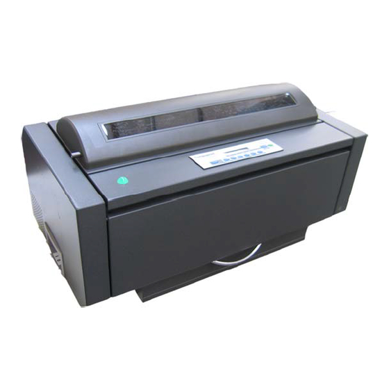
Page 13: Printer Parts
(*) The printer cabinet is available as an option. -
Page 14: Rear View
(*) The printer cabinet is available as an option. -
Page 15: Left Side View
Power Switch... -
Page 16: Setting Up Your Printer
Consider the following points when you choose the location for your printer: • The distance between the printer and the host computer must not exceed the length of the interface cable; • The location must be sturdy, horizontal and stable;... -
Page 17: Ribbon Cartridge Installation
Make sure that you are using only Compuprint original consumables. 1. Make sure that the printer is turned off. 2. Find the ribbon cartridge among the accessories Paper Bail Ribbon Shifter Holder Tension Knob Cartridge Pin... - Page 18 3. Turn the printer on and wait for printer initialization. Then press the ON LINE key to put the printer in OFF-LINE mode (check ON LINE indicator unlit). 4. Open the top cover using the handles on the front side of the covers.
- Page 19 (located on the cartridge) to take up slack in the ribbon. To avoid damage to the ribbon, do not turn the winding knob in the wrong direction. 6. Align the right and left cartridge pins with the printer locking points. Ribbon Winding Knob...
- Page 20 7. Slide and insert the ribbon guide between the print head and the ribbon guide mask holding it perpendicular to the print head. Make sure that the ribbon is inserted correctly between the print head and the print head mask. 8.
- Page 21 9. Turn again the ribbon-winding knob in the arrow direction (located on the cartridge) to take up slack in the ribbon. 10. Push the cartridge down gently until it clips into place at locking points. 11. Turn the ribbon-winding knob again in the direction of the arrow to take up slack in the ribbon. 12.
-
Page 22: Front2 Push Tractor Installation
An additional front push tractor may be installed on the printer. This Front2 push tractor unit is available as an option for the printer model. The Front2 push tractor must be installed on the Front1 push tractor. Find the Front2 push tractor among the accessories. - Page 23 Push the Front 2 tractor until it is fully engaged. Insert the connector cable in the electrical connector located in the lower push tractor.
- Page 24 Rotate the Front2 push tractor onto the Front 1 push tractor.
-
Page 25: Removing The Front2 Push Tractor
If you need to remove the upper push tractor, turn the printer off. Disconnect the connector cable and press on the push buttons to disengage the Front2 push tractor. -
Page 26: Host Computer Connection
This printer can be connected to your host computer via different available interfaces on two alternative controllers. Before connecting the interface cable, make sure that the printer and the host computer • • irst Controller: this controller provides the following three interfaces •... -
Page 27: Serial Interface
The interface connectors are located on the rear of the printer. SERIAL INTERFACE PARALLEL PARALLEL INTERFACE INTERFACE INTERFACE INTERFACE Insert the parallel interface cable into the parallel connector and fasten it by means of the clips. Insert the serial interface cable into the serial connector and fasten it by means of the two screws (use the screwdriver). -
Page 28: Software Driver Selection
Follow the instructions in the readme file you find on the CD-ROM. In a WINDOWS 95/98/2000/XP/NT4.0/Millennium®/Vista environment the printer supports the Plug & Play feature. The printer drivers of all Compuprint printers can be found at the Internet Address http://www.compuprint.com... -
Page 29: Power Connection
1. Make sure the power outlet is near the printer location and easily accessible. 2. Make sure that the power switch is in 0 position (OFF). 3. Insert the power cable plug into the printer connector and the other power cable end into a convenient outlet (the figure shows the European version). - Page 30 4. If you need to turn the printer on, press the power switch in the I position (ON).
-
Page 31: Selecting The Display Language
7. Press the key to scroll the setup languages. When the desired language is displayed, press the → key to select it. The printer exits the setup. From now on the display messages appear PROGRAM in the selected language. RELEASE KEYS... -
Page 32: Configuring The Printer
The operator panel enables you to perform many of the printer functions including paper path selections, font selection and the printer setup. The operator panel consists of: • A 16 character display (Liquid Crystal Display) • Five led indicators • Nine function keys... -
Page 33: Off Line
The printer display is used to indicate the printer status or to request an user intervention. When the printer is in Ready state, the display gives the following information: • when paper is already loaded and the printer is off line (... - Page 34 • when there is no paper loaded and the printer is off line ( ON LINE Load Front1 Current Paper Path where: LOAD FRONT1 LOAD FRONT2 OFF LINE ON LINE M1, M2, M3, M4 • when there is no paper loaded and the...
- Page 35 The printer displays only the messages related to the installed devices. When the access to the Printer Setups has been locked at the power on, the printer displays this message. The macro has been changed and the printer is updating the settings.
-
Page 36: Remote Control
This message is displayed when you can release the selection or the REMOTE CONTROL This message is displayed when the printer operates from remote control (only if the LAN interface is present). RESET & BREAK This message is displayed when the input buffer corresponding to the active interface is cleared. - Page 37 18 inch. Tear off the fanfold paper and then press the park the paper. UNLOCKED MENU When the access to the Printer Setups has been unlocked at the power on, the printer displays this message. For the error messages see "Error Handling” later in this manual.
-
Page 38: Indicators
ON LINE Blinks when there is data in the buffer and the printer is offline. Unlit when the printer is disabled and the buffer does not contain any data, or during the initialization, setup or tests. Lit when one of the printer setup procedures has been selected: Program Configuration or Power-On Configuration. -
Page 39: Function Keys
If you press the key while powering the printer on, the Power-On Configuration is selected. • If you press the key when the printer is enabled without printing or disabled ON LINE In the Program Setup mode only the four arrow keys and the enabled and the key. -
Page 40: On Line Key
Function Enables or disables the printer. • If this key is pressed while powering the printer on, the self test is printed; the printout is stopped pressing this key again. • In an error condition, once the error cause has been removed, press this key to enable the printer Pressing this key, the input buffer is cleared. -
Page 41: Micro Feed
Selects the font to be used with the currently selected pitch. The selected font is valid until the printer is turned off or a new font is selected using this key. Scrolls the parameters of the functions or macros backwards. -
Page 42: Tear/Pitch Key
The display then shows the keys is enabled ( May be used to abort paper parking procedure. See also “ Paper Parking When the printer is in Program Setup Mode, this key is disabled. Alternate Disables the alternative key functions. Function... -
Page 43: Key Combinations
2 seconds without pressing any key. Alternate Parks the paper in the currently selected paper path. PARK Function Key Combinations ONLINE + MACRO + TEAR Normal Lock or unlock the access to the printer setups. See later Function “How to Lock/Unlock the Printer Setups” section. -
Page 44: Printer Setups
The main printer setup parameters can be selected via the operator panel. The setup parameters are divided into two printer setups, the Power-On Configuration, that allows a complete configuration at installation time according to the hardware and the emulation types, and the Program Setup, that allows you to set the functions that are the most useful in your daily job. -
Page 45: Leaving The Printer Setups
STORE? CURRENT Press the keys to scan these selections forward and backwards. When the desired setting is → ← displayed, press the PROGRAM key in the Power-On Configuration the printer exits from the setup and key to exit from the Setup. -
Page 46: Power-On Configuration
2. Press and hold the PROGRAM message is displayed. As soon as the displayed: then, then, key pressed while powering on the printer until the RELEASE KEYS key gets released, the following message will be PROGRAM STARTING UP 10300 ver. x.xx PRINT OUT? NO... -
Page 47: Main Structure
Main Structure This figure shows the structure of the Power-On Configuration and how to move inside the Setup. - Page 48 → or ← PRINT OUT? YES PRINT OUT? NO ↓ EMUL. OPTIONS The Setup is not printed. PRINT OUT? NO The printer setup is printed showing the currently selected values. The PRINT OUT? YES printout starts as soon as you select this value.
- Page 49 Emulation Options This setup defines the available options according to the selected emulation and is structured as follows: Options...
- Page 50 The printer uses the EPSON LQ Series emulation. EMUL EPSON LQ The printer uses the IBM Proprinter XL24 emulation. EMUL IBM XL24 The printer uses the IBM Proprinter XL24 AGM emulation. EMUL IBM XL24AGM The printer uses the IBM Personal 2391+ emulation. EMUL. IBM 2391 The printer uses the ANSI 3.64 emulation.
- Page 51 EPSON Character Sets EMUL. EPSON LQ ↑ CHAR. SET CS1 → or ← → or ← CHAR. SET CS2 CHAR. SET ITALIC → or ← ↓ NATION CP437 These items select the character set to be used in EPSON emulation. IBM Character sets EMUL.
- Page 52 EPSON National Character sets CHAR. SET CS2 ↑ NATION CP437 → or ← NATION … → or ← NATION LATIN A1 → or ← ↓ AUTO CR YES The following national character sets are available: CP 437 CP437 G 96GREEK CP 857 CP 858 CP 860...
- Page 53 IBM National Character Sets CHAR. SET CS2 ↑ NATION CP437 → or ← NATION … → or ← NATION FARSI2 → or ← ↓ AUTO CR NO The following national character sets can be selected: CP 437 CP437 G 96GREEK CP 857 CP 858 CP 860...
- Page 54 No automatic carriage return is performed after a LF, VT or ESCJ code. Default value in IBM emulation. The printer performs an automatic carriage return after a LF, VT or ESCJ code. AUTO CR YES Default value in EPSON emulation.
- Page 55 No Automatic LF after CR. AUTO LF NO AUTO LF YES Automatic LF after CR. Only in EPSON emulation. The printer checks the AUTOFEEDXT signal AUTO LF HOST coming from the host and executes an automatic LF after CR, if the signal is low.
- Page 56 IBM Compressed Printing These items are displayed only if the IBM emulation is selected. AUTO LF NO ↑ 20 CPI IBM NO → or ← 20 CPI IBM YES → or ← ↓ BAR CODE NATIV The compressed printing is performed at 17.1 cpi. 20 CPI IBM NO The compressed printing is performed at 20 cpi.
- Page 57 Bar code mode 20 CPI IBM NO AUTOLF NO ↑ BAR CODE NATIV → or ← BAR CODE ALTER → or ← ↓ EMUL. OPTIONS Enables bar code printing using the native commands (DC4, DC4, …). BAR CODE NATIV Enables bar code printing using ANSI commands even if the emulation in use is BAR CODE ALTER EPSON or IBM.
- Page 58 Interface Settings Depending upon the installed Controller Board, the printer can be equipped with different interfaces to connect to the host system. The possible interfaces are: - Parallel Centronics - Serial 232C - USB - Ethernet LAN 10/100 The following paragraphs describe how to configure the parameters of the interfaces.
- Page 59 Parallel Interface This setup defines the use of the parallel interface and is structured according to the interface specific parameters. Parallel Interface Parameters...
- Page 60 → or ← → or ← SELECT-IN ON ↓ DATA BITS 8 The printer checks the SELECT-IN signal coming from the host. SELECT-IN HOST The SELECT-IN signal of the parallel interface is ignored and treated always SELECT-IN ON as ON.
- Page 61 Number of Data Bits SELECT-IN HOST ↑ DATA BITS 8 → or ← → or ← DATA BITS 7 ↓ INP. BUFFER 2K Selection of the number of data bits: 7 or 8. Input Buffer Size DATA BITS 8 ↑ →...
- Page 62 Serial Interface The following Serial Interface Parameters will display only if the Serial Interface is present. This setup defines the use of the serial interface and is structured according to the interface specific parameters. Serial Interface Parameters...
-
Page 63: Serial Interface
Setting the Serial Interface Parameters Interface Type PARALL INTERFACE ↑ SERIAL INTERFACE → ↓ FUNCTIONS It is available the serial interface RS-232/C only. SERIAL I/F 232 SERIAL INTERFACE ↑ SERIAL I/F 232 → or ← ↓ BAUD 9600... -
Page 64: Parity None
Baud Rate SERIAL I/F 232 ↑ BAUD 300 → or ← BAUD 600 → or ← BAUD 1200 → or ← BAUD 2400 → or ← BAUD 4800 → or ← → or ← BAUD 9600 → or ← BAUD 19200 →... - Page 65 Parity Check DATA BITS 8 ↑ → or ← PARITY NONE PARITY ODD → or ← → or ← PARITY EVEN → or ← PARITY MARK PARITY SPACE → or ← ↓ HANDSHAKE DTR Data does not have a parity bit, i.e. 8 bit data are transferred and the parity PARITY NONE check is disabled.
- Page 66 Handshake Protocol PARITY NONE ↑ → or ← HANDSHAKE DTR → or ← HANDSHAKE XONXOF ↓ CONNECTION LOCAL The Handshake is performed using the DTR Protocol. HANDSHAKE DTR The Handshake is performed using the XON-XOFF Protocol. HANDSHAKE XONXOF Connection Type HANDSHAKE DTR ↑...
- Page 67 Input Buffer Size CONNECTION LOCAL ↑ → or ← INP. BUFFER256 → or ← INP. BUFFER 2K → or ← INP. BUFFER12K INP. BUFFER32K → or ← INP. BUFFER64K → or ← INP. BUFFER128K → or ← ↓ SERIAL INTERFACE Selects the input buffer size.
- Page 68 LAN Interface The following LAN interface parameters will display only if the Ethernet 10/100 Mbit interface is present. This setup defines the use of the LAN interface and is structured according to the interface specific parameters. LAN Interface Parameters...
-
Page 69: Lan Interface
IP Assignment PARALL INTERFACE ↑ LAN INTERFACE ↓ FUNCTIONS Assigns the static or fixed IP address. IP ASSIGN FIXED Assigns the dynamic IP address (DHCP protocol). IP ASSIGN DHCP Init IP Address IP ASSIGN FIXED ↑ INIT IP ADDRESS 000.000.000.000 INIT IP ADDRESS …... - Page 70 Init Net Mask INIT IP ADDRESS 127.000.000.000 ↑ INIT NET MASK 000.000.000.000 INIT NET MASK … INIT NET MASK 255.255.255.255 ↓ DEF. GATEWAY ID 000.000.000.000 These values set the INIT net mask number. This number is represented by a decimal notation where the decimal values are divided by points in four fields.
- Page 71 Init Host Name DEF. GATEWAY ID 000.000.000.000 ↑ INIT HOST NAME …………… PROGRAM key ↓ INIT WORKGROUP CMP_GROUP The host is identified by a name. This function allows to create the name of the init host using a 14- character string. Use the ← or → keys to increase or decrease the values in one field and the ↓ or ↑ keys to move to the next field (↓...
- Page 72 Enable/Disable the SMTP Service INIT WORKGROUP workgroup ↑ SMTP ENABL. NO ↓ LAN INTERFACE Disables the SMTP (Simple Mail Transfer Protocol) service, that is disables SMTP ENABL. NO the reception/transfer/error service of the e-mail. Enables the SMTP (Simple Mail Transfer Protocol) service, that is enables SMTP ENABL.
- Page 73 E-mail Address This item is displayed only if the MAIL SERV.ADDRES 000.000.000.000 ↑ EMAIL ADDRESS xxxxxxxxxxx ↓ SENDER ADDRESS xxxxxxxxxxx This function allows to write the e-mail address where you can notify the failures. Use the ← or → keys to increase or decrease the values in one field and the ↓ or ↑ keys to move to the next field (↓ to move to the right and ↑...
- Page 74 Functions This item groups various printer functions, with which you can configure the printer. Functions Group Parameters...
- Page 75 Setting the Functions Group Items Enable/Disable the Buzzer SERIAL INTERFACE (*) LAN INTERFACE (**) ↑ → FUNCTIONS ↓ RETURN TO MFG: NO Enable or disables the buzzer. (*) If Serial Interface is present. (**) If LAN Interface is present. FUNCTIONS ↑...
- Page 76 Paper Loading Sequence BUZZER YES ↑ SEQUENCE NONE SEQ. F1+F2 PUSH ↓ BAR CODE The paper is fed only through the path selected by operator panel. SEQUENCE NONE The paper is fed firstly with the Front1 push tractor and successively SEQ.
- Page 77 Text Print Direction BAR CODE 120DPI ↑ TEXT DIRECT BI → or ← → or ← TEXT DIRECT UNI ↓ GRAPH DIRECT BI Selects the print direction for text: bidirectional or unidirectional. Graphics Print Direction TEXT DIRECT BI ↑ → or ← GRAPH DIRECT BI GRAPH DIRECT UNI →...
- Page 78 Bar Codes Print Direction GRAPH DIRECT BI ↑ → or ← BARCODES DIR. BI BARCODES DIR. UNI → or ← ↓ GRAPH H.S. YES Selects the print direction for bar codes: bidirectional or unidirectional. Graphics Printing Speed Selection BARCODES DIR. UNI ↑...
- Page 79 MENU ENGLISH The paper path at power-on is the one from the default Macro. P. ON PATH MACRO The paper path at power-on is the last one that was selected before the printer P. ON PATH LAST was powered off.
- Page 80 Selection of the Language of the Display Messages P. ON PATH MACRO ↑ MENU ENGLISH → or ← MENU ITALIANO → or ← MENU FRANCAIS → or ← MENU ESPANOL → or ← MENUE DEUTSCH → or ← ↓ F1 JAM SENS. Y These items are self explaining.
- Page 81 Enable/Disable Lower Tractor Jam Sensor MENU ENGLISH ↑ F1 JAM SENS. Y → or ← F1 JAM SENS. N → or ← ↓ F2 JAM SENS. Y TEAR ADJUST:xxx Enables the paper jam sensor located in the 6 pin Front1 push tractor option. F1 JAM SENS.
- Page 82 Adjusting the Tear-Off Position F2 JAM SENS. Y F1 JAM SENS. Y MENU ENGLISH ↑ TEAR ADJUST: +30 TEAR ADJUST: ... TEAR ADJUST: -390 ↓ FUNCTIONS TEAR ADJUST: xxx See also “How to Use the Tear-Off Function”, later in this Chapter. →...
-
Page 83: Print Out
At this point, the Power On Configuration Setup procedure is finished. If you exit pressing the ↓ and key, the new settings will be saved. PROGRAM Do not power off the printer before all data have been written into the NVM and the printer has returned online. → or ←... -
Page 84: Program Setup
The default values of the various functions are indicated in bold. Press the key when the printer is turned on and is offline or online without printing. The PROGRAM following message will be displayed: The figure in the following page shows the structure and how to move inside the Program Setup. - Page 85 Main Structure Print out? No Print out? Yes User Macro Macro # 1 Line sp. 6 lpi Next Macro? No Config. Menu No Config. Menu Yes Hex Dump No Hex Dump Yes The items define the following parameters: • Four user macros •...
-
Page 86: User Macro
↓ USER MACRO The setup is not printed. PRINT OUT? NO The printer setup is printed. The printout starts as soon as you select this value. PRINT OUT? YES NOTE: The Program setup printout indicates: • the currently selected values, •... - Page 87 The USER MACRO item allows to prepare four printing environments (MACRO#1, MACRO#2, MACRO#3 and MACRO#4). Each macro is composed of a group of parameters which define a configuration that can then be recalled to easily set the printer for four printing environments. Selection of the User Macro PRINT OUT? NO ↓...
- Page 88 User Macro Parameters User macro Macro #1 Macro #2 Macro #3 Macro #4 Line sp. 6 lpi Line s p..Line Sp. Lock No Line Sp. Lock Yes Length 66 Lines Length ... Top of Form 0 Top of Form … Ignore F.F.
- Page 90 Line Spacing → MACRO#1 These values define the line spacing in lines/inch (6, 8, 12) or in lines per 30 mm (3, 4, 6, 8, 12). Line Spacing Lock LINE SP. 6 LPI ↑ → or ← LINE SP. LOCK NO LINE SP.
- Page 91 Page Length LINE SP. LOCK NO ↑ → or ← LENGTH 1 LINE → or ← LENGTH ... LINES → or ← LENGTH 244 LINES ↓ TOP OF FORM 0 These items set the page length for fanfold paper in number of lines depending on the current vertical spacing.
- Page 92 Form Feed (FF) Command TOP OF FORM 0 ↑ IGNORE F.F. NO → or ← → or ← IGNORE F.F. YES ↓ SKIPOVER 0 IGNORE F.F. NO The Form Feed (FF) command is always executed. The Form Feed (FF) command is ignored when the paper is in the top of form IGNORE F.F.
- Page 93 QUALITY LQ The printer performs the draft printing at normal speed. DRAFT MODE NORM The printer performs the draft printing at low speed to obtain better quality DRAFT MODE BEST printing. The printer performs the draft printing at high speed.
- Page 94 Font Selection QUALITY LQ ↑ FONT Draft → or ← → or ← FONT Courier → or ← FONT OCR-B FONT Gothic → or ← → or ← FONT Prestige → or ← FONT Present FONT OCR-A → or ← →...
- Page 95 Pitch Selection FONT Draft ↑ PITCH 5 CPI → or ← PITCH 6 CPI → or ← → or ← PITCH 7.5 CPI PITCH 8.5 CPI → or ← PITCH 10 CPI → or ← → or ← PITCH 12 CPI PITCH 15 CPI →...
- Page 96 Micro Dot Print Mode PITCH 10 CPI ↑ 15&24CPI NORMAL → or ← → or ← 15&24CPI MICRO ↓ PITCH LOCK NO The print matrix uses 8 x 8 dots only if the horizontal spacing is 15 or 24 cpi 15&24CPI MICRO (micro mode).
- Page 97 Left Margin PITCH LOCK NO ↑ → or ← LEFT MARGIN 0 LEFT MARGIN ... → or ← LEFT MARGIN xxx → or ← ↓ RIGHT MARGIN 136 The Left Margin is set in number of columns (depending on the current pitch) starting from the physical left edge.
-
Page 98: Right Margin
You can select the Zero character printing with or without a slash. Paper Path Selection This function defines the default paper path for the current macro. Paper Path selection depends upon the printer model and the installed options. SLASH ZERO NO ↑... - Page 99 The Tear-Off Function is performed pressing the TEAR NORMAL offline. When the printer is not receiving any data, the paper is moved to the Tear-Off TEAR AUTOMATIC position. It is returned to the Tear-Off position as soon as it receives printing data.
- Page 100 ↓ STRONG IMPACT This item defines the time that printer uses to move paper to the Tear-Off position in automatic tear mode. The range of the tear delay is between 1 and 5 seconds. The default value is 1 sec.
- Page 101 Print Impact Strength TEAR DELAY 1 ↑ → or ← STRONG IMPACT → or ← SOFT IMPACT ↓ PERFOR. SAFE NO The impact strength of the print head is set for printing on multicopy paper. STRONG IMPACT The impact strength of the print head is set for printing few copies. SOFT IMPACT The printing noise is reduced.
- Page 102 Quiet Printing PERFOR. SAFE NO ↑ QUIET PRINT OFF → or ← → or ← QUIET PRINT ON ↓ AUTOGAP 0 QUIET PRINT OFF The function is disabled. Printing at normal noise level. QUIET PRINT ON The function is enabled. Printing at reduced noise level.
- Page 103 Default value is AUTOGAP 0. Selecting this item, the print head must be adjusted manually. MANUAL GAP FIXED GAP xxx Selecting one of these values the printer adjusts the print head gap to a fixed distance.
- Page 104 Horizontal Character Tuning AUTOGAP 0 ↑ TUNING: HORIZ 0 → or ← → or ← TUNING: HORIZ ... → or ← TUNING: HORIZ 60 ↓ TUNING: VERT 0 These values adjust the distance between the left paper margin and the first print character. The values correspond to 1/120 inch units, i.e.
- Page 105 Resetting the Macro Parameters to the Factory Defaults TUNING: VERT. 0 ↑ → or ← MACRO -> MFG NO → or ← MACRO -> MFG YES ↓ NEXT MACRO? NO The new values set for the macro parameters will be the used. MACRO ->...
- Page 106 Selecting Another Macro MACRO -> MFG NO ↑ NEXT MACRO? NO → or ← NEXT MACRO? YES ↓ CONFIG MENU NO To pass over to another macro, select NEXT MACRO YES. Pressing the ↓ or ↑ key the item MACRO#1 is displayed, then press the →...
- Page 107 Passing over to the Power-On Configuration At this point of the setup, it is possible to pass over to the Power On Configuration functions setting. NEXT MACRO NO ↑ → or ← CONFIG MENU YES CONFIG MENU NO ↓ HEX DUMP NO These items are self-explaining.
- Page 108 The values set are stored permanently (in the NVM) and will be used until they STORE? SAVE are changed by the operator. The values set are valid until the printer is turned off. When you turn the printer STORE? CURRENT on again, the values set in the preceding setup will be used.
-
Page 109: Ansi Emulation
CHAR SET CS1 → or ← → or ← CHAR SET CS2 ↓ CH.TAB CODE 437 The printer uses the CS1 character set. CHAR SET CS1 The printer uses the CS2 character set. CHAR SET CS2 ANSI Code Pages CHAR. SET CS2 ↑... - Page 110 RIS ENABLE NO ↓ RIS ENABLE YES If the printer receives a command (ESC c) from the host to reset the printer, then the printer will (YES) or will not (NO) reset the current configuration to the power-up configuration. FRANCE B...
- Page 111 ↓ AUTO CR YES If the printer receives a command (SI or SO) from the host to enable or disable the special modes (oversize, expanded and bar code modes), then the printer will (YES) or will not (NO) respond to the <SI> and <SO> commands based upon your selection.
- Page 112 PRIME ON DEL NO ↓ CONTRL IN DG YES If the printer receives a command (DEL) from the host, then the printer will (YES) or will not (NO) perform a prime (reset) based upon your selection. Control Codes in Dot Graphics PRIME ON DEL YES ↑...
- Page 113 Vertical Expansion CONTRL IN DG YES ↑ EXPAND UP YES → or ← → or ← EXPAND UP NO ↓ ALT GRAPHICS YES This setting defines the vertical expansion from the baseline up (YES) or from the top line down (NO).
- Page 114 ↓ S/SUB SCRIPT YES If the printer receives a control code command (80H to 9FH) whose eighth data bit is set, and the character set is selected, then the printer will (YES) or will not (NO) respond to the particular code based upon your selection.
- Page 115 ESC+Control Code S/SUB SCRIPT YES ↑ ESC+ CTR CODE YES → or ← → or ← ESC+ CTR CODE NO ↓ VT NOT SET YES In this setting the control codes embedded within escape sequence are valid (YES) or ignored (NO).
- Page 116 DOUBLE LF NO ↓ DOUBLE LF YES If the printer receives a command (LF) from the host to execute a line feed, then the printer will (Y) or will not (N) also perform double line feed based upon your selection. Automatic Wrap DOUBLE LF YES ↑...
- Page 117 Clear Margin AUTO WRAP YES ↑ CLEAR MARGIN YES → or ← → or ← CLEAR MARGIN NO ↓ BACKOP NINE Clears (Y) or preserves (N) top and bottom margins on form length changes.
- Page 118 The printer will return the print head to the vertical position established before turning on Oversize modes at the completion of printing of the current barcode symbol. The printer will return the print head to the vertical position established before turning on both BOTH Barcode and Oversize modes at the completion of printing of the current barcode symbol.
- Page 119 ↓ EMUL. OPTIONS The printer will (Y) or will not (N) include left, right and center Guard bars of the barcode styles which use Guard bars based upon your selection. The Guard bars extend into the human readable line of the barcode symbol when it is enabled.
-
Page 120: How To Select The Paper Path
The paper can be loaded into the printer using different paper paths. The messages indicating the paper paths are shown depending upon the printer model and if the corresponding loading device is installed on the printer. Proceed as follows: 1. Press the... -
Page 121: How To Use The Tear-Off Function
This function is used to match the paper perforation with the tear-off bar. For this function the following values must be set: 1. Press the key when the printer is disabled or enabled without printing to enter the PROGRAM Program Setup. -
Page 122: Adjusting The Tear-Off Position
To check the Tear-Off Position proceed as follows: 1. Check if the paper perforation matches the tear-off bar on the printer. 2. To move manually the paper to the Tear-Off position, press the key when the printer is TEAR enabled without printing (TEAR NORMAL function selected YES in the Program Setup). -
Page 123: Selection Of The Tear-Off Mode
→ ← Pressing the TEAR NORMAL Pressing again the moved to the printing position. If the printer is not receiving data, the paper is moved automatically to the TEAR AUTOMATIC tear position. TEAR LABEL when printing on labels. Pressing the toward the back of the printer. -
Page 124: How To Lock/Unlock The Printer Setups
Now the access to the printer setups is locked. If the message is displayed (the • If you decide to unlock the printer setup, turn the printer off, then press the keys at the same time and keep them pressed while powering the printer on again TEAR until the display shows RELEASE KEYS message. -
Page 125: How To Handle The Paper Parking
• When the paper is positioned at the first printable line and the paper path is changed (changing the Macro or pressing the or the key is pressed, the printer PARK performs automatically the parking procedure. • If at least one line has been printed, or the... - Page 126 (changing the Macro or pressing the key is pressed, the PARK printer performs automatically the parking procedure. • If at least one line has been printed, or the paper has been fed forward at least 1 line and the...
- Page 127 (changing the Macro or pressing the key) or the PATH pressed, printer automatically the parking procedure. • If at least one line has been printed, or the paper has been fed forward at least 1 line and the paper path is changed...
-
Page 128: The Printer
PATH pressed automatically ejects the paper towards the rear of the printer. • If at least one line has been printed, or the paper has been fed forward at least 1 line and the paper path is changed... - Page 129 The display shows OPER. INTERRUPTED. If in any of the above cases you do not tear off the paper and the printer is not able to park it, because it is too long, the display shows TEAR OFF PAPER/PARK PAPER. Tear off the paper and press again the key.
-
Page 130: Paper Handling
It is important to use the correct paper for obtaining the best performance. See the information table below: Loading Mode Width Length Thickness Copies Weight (g/m - Original - Other sheets - Carbon Paper Front1 Tractor 76 to 432 mm 3 to 17 inches 76 to 609 mm 3 to 24 inches... -
Page 131: Fanfold Paper Loading
• If you have been using a different path, the display shows: • If you have been using fanfold paper in the Front2 push tractor paper path (if the Front2 push tractor option is installed), the printer automatically starts the parking procedure. The display shows alternately: TEAR IF NECESS. - Page 132 2. Open the Push tractors cover turning it upwards until it stops. 3. If installed, rotate the Front2 tractor outside of the printer.
- Page 133 4. Unlock the sprockets of the Front1 tractor moving the sprocket levers up. Slide the left sprocket to the first printing column. For easier understanding some of the following pictures show the printer without the Front 2 tractor installed.
- Page 134 Space the paper guides along the tractor bar. Open the left and right sprocket covers. 6. If installed, insert the fanfold paper between the lower and the upper tractor.
- Page 135 Hold the fanfold paper in front of the sprockets insert perforation on the left sprocket pins and close the sprocket cover. 8. Insert the paper on the right sprocket pins, make sure the paper goes under the paper sensor and close the sprocket cover.
- Page 136 9. Match the left sprocket for the first printing position, i.e. the left paper margin must match the ninth mark on the printer cabinet. 1 2 3 4 5 6 7 8 9 10...
- Page 137 10. Adjust the right sprocket gently to remove slack from the paper. Make sure the paper is not taut. 11. Lock the left and right sprockets moving the sprocket levers up.
- Page 138 12. If installed, reposition the Front2 tractor in its initial position. 13. If your printer is installed on a table, position the paper staple so that the paper is freely fed into the printer. If your printer is installed on the optional...
- Page 139 ON LINE The printed paper is output on the rear side of the printer. If your printer is located on the optional printer cabinet, the printed paper is collected on the output stacker: key to load the paper into the printer.
- Page 140 If the printer is not installed on the cabinet, make sure that there is enough space to stack the printed paper:...
-
Page 141: Loading Paper Using The Front2 Tractor
1. To select the Front2 tractor paper path press the • If you have been using a different path, the display shows: • If you have been using fanfold paper in the Front 1 tractor paper path, the printer automatically starts the parking procedure. The display shows alternately. - Page 142 2. Open the tractor area cover turning is upwards until it stops. 3. Unlock the Front2 tractor sprockets moving the sprocket levers up.
- Page 143 4. Space the paper guides along the tractor bar. Open the sprocket covers of the left and right sprocket. 5. Hold the fanfold paper in front of the sprockets and insert the paper perforation on the left sprocket pins and close the sprocket cover. 6.
- Page 144 7. Position the left sprocket for printing, matching the left paper margin with the eleventh notch on the printer cabinet and lock it in place. 1 2 3 4 5 6 7 8 9 10 8. Adjust gently the right sprocket to remove slack from the paper.
- Page 145 ON LINE is displayed: LOAD FRONT2. 12. Press the key to load the paper into LOAD/FF the printer. 13. Press the key, now the printer is ON LINE ready to print. The paper is ejected from the rear of the printer.
-
Page 146: Printer Maintenance And Troubleshooting
Make sure the printer has been turned off for at least 15 minutes before starting any cleaning Periodic cleaning will help keep your printer in top condition so that it will always provide optimal performance. • Use a neutral detergent or water solution on a soft cloth to clean dirt and grease from the cabinet of the printer. -
Page 147: Replacing The Ribbon Cartridge
1. Make sure that the printer is turned off for at least 15 minutes. Pay attention to the print head because it becomes hot during operation. 2. Open the top printer cover. 3. Slide the ribbon guide out of the print head. - Page 148 4. Free the shifter holder pushing the tab towards the rear and pulling the shifter holder up. 5. Remove the used ribbon cartridge by lifting it up. Now, you are ready to insert the new ribbon cartridge. See before Installation”. “Ribbon Cartridge...
-
Page 149: Printing The Self Test
If you need to know any printer setting, and to check if the printer is working well, print the self- test. Proceed as follows: 1. Keep the key pressed while powering on the printer until the display shows ON LINE RELEASE KEYS. -
Page 150: Error Handling
When an error condition occurs: • the printer is disabled; • the first message on the display indicates the error, while the second message gives more details concerning the error conditions. Press always the ON LINE key to reset the error condition. -
Page 151: Buffer Overflow
Check the paper path and remove the jammed paper. Press the the error condition. Call Service. Turn the printer off and then on again. If the problem is not solved call Service. key successively key to reset ON LINE... - Page 152 A tractor type that is not UNKNOWN TRACTOR recognized has been mounted on the printer. Solution Check all the paper paths and remove the jammed paper. Press the the error condition. Check that the ribbon is correctly inserted.
-
Page 153: Repacking The Printer For Shipment
If you need to ship your printer, it is necessary to repack it to avoid damaging during the transport. Proceed as follows: When repacking the printer always use the original packing material 1. Find the packing material and the repacking kit. - Page 154 2. Open the upper printer cover and fix the print head and the bail with the fixing strip. 3. Open the tractor area cover, move the paper guides to the center of the tractor and fix the two transport screws.
- Page 155 4. With the help of another person move the printer onto the transport foam on the transport pallet. Insert the plastic bag over the printer and the foam shells on both sides of the printer. 5. Slide the packing box over the printer and insert the accessories onto the printer.
- Page 156 7. Close the packing box and fix it to the transport panel by means of the packing strip, inserting the plastic angles between the packing strip and the carton. 8. Fix the packing strip with the corresponding clips.
-
Page 157: Options
The Front2 Push Tractor is available as an option for the printer model. The printer cabinet is available as an option for the printer model. For the cabinet assembly, please refer to the instructions included in the cabinet packing box. -
Page 158: Installing The Controller Board
• Before removing the Controller Board from the protective package, ground the package to exposed metal at the back of the printer. This will release any static charge that may have developed on the package or on your body. Hold the package against the metal for at least two seconds. - Page 159 3. Use the information under “Handling the Controller Board” on the preceding page as you remove the Controller Board from its shipping box and from the protective package. 4. Align the left and right sides of the Controller Board with the guides in the printer and slide it into the slot.
- Page 160 5. Gently push the Controller Board into the printer until it is seated in the connector inside the printer. The Controller Board is correctly seated in the printer when the Controller Board metal plate is aligned with the back profile of the slot.
- Page 161 6. Attach the Controller Board with the two screws using the screwdriver that came in the Controller Board box.
-
Page 162: Printing Characteristics
Printing Characteristics Print Head Matrix 24 pins Print Head Life 800 mil characters (draft) Print Speed (cps) 10 cpi 12 cpi micro 15 cpi normal 15 cpi Lines per minute @10 cpi in HS Draft mode Throughput (ISO/IEC 10561) 750 pages per hour Draft HS Draft Normal... - Page 163 Print Matrix (horizontal x vertical) HS Draft 10 cpi 9 x 12 12 cpi micro 15 cpi normal 15 cpi 17,1 cpi 20 cpi micro 24 cpi normal 24 cpi Print Density (characters per inch) Normal 10 - 12 - 15 - 17.1 - 20 - 24 Line length (number of characters) 10 cpi 12 cpi...
- Page 164 Print Styles Draft - Courier - OCR B - Gothic - Prestige - Present - OCR A - Script Print Attributes Sub-superscript, Underline, Overscore, Italics, Emphasized, Double Strike, Shadow, Enlarged, Compressed Graphic Resolution (dots per inch) horizontal vertical Characters Sets Standard PC IBM Character Sets EPSON National Variations IBM and EPSON Character Sets...
-
Page 165: Paper Handling
Fanfold width: 76 to 432 mm Copies: 1 original + 7 copies - IBM Proprinter XL24 - IBM Personal Printer 2391+ - ANSI 3.64 (3 to 17 inches) Max. thickness 0,635 mm (0.025 inches) (3 to 17 inches) Max. thickness 0,635 mm (0.025 inches) -
Page 166: Physical And Electrical Characteristics
• Automatic fanfold positioning for tear-off, selectable time-out • Setting and storage of paper format and print conditions for each paper path in the non volatile memory • Printing of the macro characters using the Compuprint native commands Physical and Electrical Characteristics... - Page 167 Mean Time between failure: 10000 hours at 25% DC MTTR Mean Time To Repair: 30 minutes Workload 60000 pages/month (ECMA 132 - 4 hours for 22 days) Printer Life 5 years or 10000 hours @25% Duty Cycle Operating: no limitations Power Supply...
- Page 168 Depth 400 mm (15,75 inches) Weight 33 kg Physical dimensions – Printer Cabinet Height printer table: 666 mm (16,92 inches) paper stacker: 512 mm (13,01 inches) Width 726 mm (18,44 inches) Depth without paper stacker: 522 mm (13,26 inches) with paper stacker: 794 mm (20,17 inches)
- Page 169 Consumables Black “Long Life” cartridge (25 million characters) Options Printer Cabinet Front2 Tractor Controller Parallel-Serial-USB Controller Parallel-Ethernet LAN Standards CE Mark UL 1950; CSA 22.2 n.950; EN 60950 CISPR 22/EN 55022-class B; FCC rules part 15, subpart J, class B...
- Page 170 78413012-001 Sferal WWT proprietary. All trademarks herein recalled are registered by their respective companies.
Need help?
Do you have a question about the 10300 and is the answer not in the manual?
Questions and answers