Table of Contents
Advertisement
Quick Links
Advertisement
Table of Contents

Related Manuals for Compuprint MDP40B


Summary of Contents for Compuprint MDP40B
- Page 1 Rev. 003...
-
Page 2: Compuprint Information
• other standards Compuprint advises the customers not to use products for which the compliance to this safety rules are not warranted. Finally seek your dealer or contact a Compuprint office and be sure that are provided you the original Compuprint consumables. -
Page 3: Table Of Contents
Parallel Interface ...23 Serial Interface ...23 Printing a Test Page ... 25 Printer Setup ...27 Printing the Printer Setup Forms ...27 Filling in the Printer Setup Forms ...30 Reading the Preprinted Forms ...31 Printer Setup Flow Chart...32 Setup Parameters ...33 Offset Adjustments...44 Troubleshooting ...47... -
Page 5: Printer Presentation
• Easy paper handling The operator places the paper on the front table and the printer loads it without any other user intervention. The paper ejection towards the front or the rear of the printer allows an easy access to the printed document. - Page 6 • Standard parallel and serial interface and automatic switch-over function. The financial interface is available for the IBM 4722 and the IBM 9068 protocols. • Easy printer setup • Supported emulations: Epson 570, IBM Proprinter XL24E, XL24E AGM, IBM 2390+, 4722,...
-
Page 7: Unpacking The Printer
• Paper stand • Ribbon cartridge • Power cable • CD-ROM with the printer documentation and drivers. Always keep the packing material in a safe place as you must repack the printer into it, when you need to move it. -
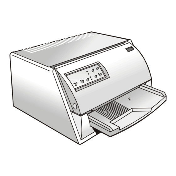
Page 8: Printer Parts
Never remove any printer part unless it is expressly indicated in this manual. O p erato r P a ne l P rin ter C o ver P ap er S tan d... -
Page 9: Printer Installation
• Your printer must not be exposed to direct sunlight, extreme heat, cold, dust or humidity; • You need an AC power outlet compatible with the plug of the printer’s power cord. The voltage of the outlet must match the voltage shown on the printer’s Name Plate;... -
Page 10: Installing The Paper Stand
1. Open the printer cover. 2. Match the hooks on the lower side of the paper stand with the clefts on the printer front part. - Page 11 3. Holding the paper stand oblique insert the hooks into the printer clefts. 4. Lower the paper stand to horizontal position making sure that the two holders on both sides are correctly inserted into the corresponding slots. Press the paper stand down until it clips into place.
-
Page 12: Installing The Power Cable
DO NOT CONNECT THE PRINTER TO THE MAINS. Consult your dealer for help. Always use a grounded outlet. 2. Insert the power cable into the connector on the printer and the other end into a convenient mains outlet. -
Page 13: Installing The Ribbon Cartridge
To install the ribbon cartridge, the printer must be powered on. 1. Remove the cartridge from its bag. Turn the tension knob in the direction of the arrow to tighten the ribbon. Do not remove the plastic mask from the ribbon cartridge. The ribbon cartridge may not be used... - Page 14 2. Open the printer cover, the print head moves to the ribbon installation position. 3. Hold the ribbon cartridge slightly inclined with the ribbon mask in front of the print head.
- Page 15 Push the cartridge onto the print carriage until it clicks into place. 5. Turn the tension knob in the direction of the arrow to tighten the ribbon. 6. Close the printer cover.
-
Page 16: Paper Handling
This printer is designed for versatile and reliable paper handling. The flat-bed mechanism allows the handling of special documents, such as multiple invoices, postcards, labels, passbooks and tickets. The print head detects the paper edges automatically, the sheet can therefore be inserted in any position within the detection area according to the rules described in the following paragraph. - Page 17 • The documents having a width of at least 90 mm must be inserted on the left hand side over the grooved area on the paper stand. The documents must cover the whole grooved area, otherwise the printer will not accept the paper.
- Page 18 • To load the documents having a width of less than 90 mm: − make sure that in the program menu the MANUAL LOADING item is enabled. − hold the paper against the left paper guide of the paper support while inserting it into the printer...
-
Page 19: Loading Passbooks
If you insert damaged documents or paper with foreign material, you can seriously damage the • Before inserting a passbook into the printer, open it and crease it in both directions along the binding stitch, so that the passbook lays flat on the paper stand when it is inserted into the printer. - Page 20 • The passbooks must be inserted on the left hand side over the grooved area on the paper stand. They must cover the whole grooved area, otherwise the printer will not accept the passbooks. • The passbooks with horizontal fold must have a minimum width of 102 mm.
- Page 21 • The passbooks (both with horizontal and vertical fold) must not exceed the right passbook margin on the paper stand (second line from the right). R ight P a ssboo k M argin...
-
Page 22: The Operator Panel
The operator panel is located on the front left side of the printer and is composed of function keys and leds with which you can easily check the printer status and select the functions as described below: Turns the printer on or off. - Page 23 EJECT Ejects the inserted form. This key is active, when the printer is offline or when the printer is online and no print data are in the buffer. When pressed while powering the printer on, the hexadecimal printing is selected.
-
Page 24: Leds
When using the other protocols, these leds are disabled. In case of a printer fault during the initialization of the LQ, P1, P2 and ON LINE indicators blink contemporaneously. Turn the printer off and on again. If the problem is not solved, call the “Printer... -
Page 25: Software Driver Selection
This printer supports the Plug&Play facility in the Windows95/98/2000® environment. If you want to install the printer in the Windows environment, insert the CD-ROM and follow the instructions given. The printer drivers of all Compuprint printers can be found at the Internet Address http://www.compuprint.net/drivers... -
Page 26: Connection To The Host
This printer can be connected to the host by means of a parallel standard Centronics or bidirectional IEEE 1284 type interface or by means of the serial RS-232/C interface. Proceed as follows: Make sure that both the host and the printer are turned off. -
Page 27: Setting The Interface Parameters
The printer enters the Setup mode. 2. Insert a blank sheet in A4 or Letter format. The printer loads the sheet and stops. The leds are lit. - Page 28 If more than one value is set for a parameter, the printer ignores these parameters and maintains Do not fill in the marker beside the title of the preprinted form, otherwise the printer will not be 6. Once the serial interface parameters have been signed, insert the sheet back into the printer.
-
Page 29: Printing A Test Page
It is now useful to test, if the printer has been correctly installed. For this purpose print the self test page as follows. 1. Press the key while powering the printer on and hold the key pressed until all leds ON LINE turn briefly on. -
Page 30: Program Setup
PROGRAM SETUP PROTOCOL FONT HORIZONTAL PITCH VERTICAL PITCH FORM LENGTH LEFT MARGIN RIGHT MARGIN TOP MARGIN BOTTOM MARGIN IBM C-SET IBM COMPRESS EPSON C-SET NATION C-SET CODE PAGE OLIVETTI C-SET VERT. RESOLUTION RESET WITH EJECT LINE MODE WRAP MODE SLASHED ZERO PRINT DIRECTION EJECT ON FF CUT SHEET EJECT... -
Page 31: Printer Setup
The printer enters the Setup Mode. If you already have the preprinted forms for the printer setup, go to “Filling in the Printer Setup Insert a blank sheet in A4 or Letter format. The printer loads the sheet and stops. The leds are lit. -
Page 32: On Line Key
= lit = unlit The printer setup forms contain all printer parameters and the values that can be set. The current value is indicated by an asterisk (*). For a detailed description of the parameters and the settings see “Setup Parameters” later in this “Printing a Test... - Page 33 Each printer setup form is identified by a marker in the upper left corner of the page as follows: Configuration Setup) Program 1 Program 2 If you press the key: The printing of the printer setup forms starts. The forms are printed according to the selection made with the key.
-
Page 34: Filling In The Printer Setup Forms
If more than one value is set for a parameter, the printer ignores these parameters and maintains Do not fill in the marker beside the title of the preprinted form, otherwise the printer will not be Do not use pencils. -
Page 35: Reading The Preprinted Forms
When the Printer Setup Forms have been filled in, insert them back into the printer. The printer is able to recognize the Setup Forms by means of the markers on these pages. The printer reads the values marked for the various parameters and configures the printer accordingly. -
Page 36: Printer Setup Flow Chart
S elf Te st P rin ter O FF O N L IN E PR O G R AM PR O G R AM PR O G R AM PR O G R AM N o rm al M ode... -
Page 37: Setup Parameters
Description The selected values are not set to factory defaults. The values set in all printer setups are reset to factory default values. The values set in the configuration setup are reset to factory default values. The values set in the corresponding program setup are reset to the factory default values. -
Page 38: Interface Type
1 Kb, 8 Kb, 16 Kb, 32 Kb IGNORE PE enabled, disabled Selects whether the printer signals the paper empty condition AUTOFEED SIGNAL disabled, enabled The parallel interface uses (enabled) or does not use (disabled) the SLCT-IN SIGNAL disabled, enabled The parallel interface uses (enabled) or does not use (disabled) the Description Selects the interface type. -
Page 39: Buffer Control
Setup Parameter Values BUFFER CONTROL DTR, XON/XOFF, XON/XOFF+DTR ROBUST XON enabled, disabled Perform the Robust XON (enabled) or not (disabled). WORD LENGTH 7 bit, 8 bit BAUD RATE 600 - 38400 bps PARITY BIT even, odd, none SECURITY MODE enabled, disabled Enables or disables the security actions that assure protection against PASSBOOK TYPE Fixed thick Vertical... - Page 40 Selects the passbook width setting mode. Selecting auto the width of the passbook is read and set automatically by the printer, independently from the passbook width set by menu or software command. Selecting setup the width of the passbook is set by the user in the menu or by means of a software command.
- Page 41 Selects the passbook length setting mode. Selecting auto the length of the passbook is read and set automatically by the printer, independently from the passbook length set by menu or software command. Selecting setup the length of the passbook is set by the user in the menu or by means of a software command.
- Page 42 PROGRAM 2 Description Defines the printer protocol. NOTE: For the IBM 4722 and 9068 protocols, if the software driver uses the controlled link of the IBM financial driver, set the INTERFACE TYPE item in the Configuration Menu to financial.
-
Page 43: Form Length
Setup Parameter Values LOCK no lock, font, hor. pitch, font+hor.pitch FORM LENGTH # lines, A4, letter, A5, legal Example: How to set the form length to 82 lines: FORM LENGTH #lines A4 Setup Parameter Values LEFT MARGIN 10 x Description The following selections made via operator panel may be locked: font, horizontal pitch (hor.pitch), or both the font and horizontal pitch (font+hor. -
Page 44: Right Margin
Example: How to set the Left Margin to 20. LEFT MARGIN 10 x Setup Parameter Values RIGHT MARGIN 100 x 10 x Example: How to set the Right Margin to 101. RIGHT MARGIN 100 x 10 x Setup Parameter Values TOP MARGIN 10 x Description... -
Page 45: Bottom Margin
Example: How to set the Top Margin to 15. TOP MARGIN 10 x Setup Parameter Values BOTTOM MARGIN 10 x Example: How to set the bottom margin to 34 lines: BOTTOM MARGIN 10 x Setup Parameter Values IBM C-SET IBM set 1, IBM set 2 IBM COMPRESS 17.1 cpi, 20 cpi EPSON C-SET... - Page 46 Setup Parameter Values NATION C-SET USA, FRANCE, GERMANY, ENGLAND, DENMARK1, SWEDEN, ITALY, SPAIN1, JAPAN, NORWAY, DENMARK2, SPAIN2, LATIN A1 CODE PAGE CP437, CP437G, 96GREEK, CP850, CP851, CP852, CP853, CP855, CP857, CP858, CP860, CP862, CP863, CP864, CP865, CP866, CP867, CP876, CP877, CP1098, CP1250, CP1251, CP1252, GOST, TASS, MAZOWIA, CP437SL, UKRAIN, 8859/1, 8859/2, 8859/3, 8859/4,...
- Page 47 Setting used for the OLIVETTI protocols. If the printer receives a LF code (LF), it only performs a line feed. If the printer receives a CR code (CR), it only performs a carriage return.
-
Page 48: Manual Loading
For a precise adjustment of the position of the printed characters on a preprinted form, this printer allows to easily adjust the first line and the first printing column as follows: 1. Press the key while powering the printer on. - Page 49 OFFSET TUNING SETUP Vertical Position Offset (1/10 INCH) PROGRAM 1 ( )* PROGRAM 2 ( )* Vertical Offset Tuning (1/60 INCH) PROGRAM 1 PROGRAM 2 Horizontal Position Offset (1/10 INCH) PROGRAM 1 ( ) ( ) ( ) ( ) ( ) ( ) ( )* ( ) ( ) ( ) ( ) ( ) ( ) ( ) ( ) ( ) PROGRAM 2 ( ) ( ) ( ) ( ) ( ) ( ) ( )* ( ) ( ) ( ) ( ) ( ) ( ) ( ) ( ) ( ) Horizontal Offset Tuning (1/60 INCH) PROGRAM 1 PROGRAM 2...
- Page 50 Horizon tal O ffset Tun ing 3. Fill in the marker corresponding to the value you want to set and reinsert the sheet into the printer. The printer reads the selected values and sets them. 4. Turn the printer off.
-
Page 51: Troubleshooting
In case a paper jam condition occurs, proceed as follows: 1. Open the printer cover. 2. Pull the lever on the right inner side of the printer towards the printer front side to open the paper path and with the other hand hold pressed the paper path cover. - Page 52 3. Remove the jammed paper. 4. In case it is not possible to remove the jammed paper because you cannot reach it with your hand or it is embedded so that you cannot move it, rotate the white cog-wheel beside the paper path lever to free the paper.
- Page 53 5. To close the paper path, push the paper path cover down until it locks in position.
-
Page 54: Print Quality Problems
EJECT 2. The data sent to the printer are printed in three columns where the first column indicates the number of the line, the second shows the hexadecimal values corresponding to the transferred data and the third column shows the corresponding ASCII values. -
Page 55: Paper Specifications
• Never print on documents with metallic or hard plastic fasteners or staples, they may damage the printer. Use only sewn passbooks. • To get the maximum print contrast you should print on white or light colored paper. You may overstrike to improve the low contrasting paper. -
Page 56: Cuts Sheets
Dimensions Form width Form length Distance between dot position and left or right paper edge Distance between top of the first printed line and top margin of the document Distance between the lower margin and the lower part of the last printed line Weight Thickness Copies... -
Page 57: Passbooks
Paper Weight Thickness Multiple Page Passbooks Horizontal Fold Thickness difference across the fold of an open passbook Horizontal Fold Vertical Fold Single Page Passbook or Ledger Cards • Passbooks with torn, folded, creased, incomplete or warped pages or covers should not be used. -
Page 58: Passbooks With Horizontal Fold
Insertion direction P rint A rea A BC D A BC D P rint A rea Dimension Passbook width Passbook length Distance between print character position and left or right edge Distance between top edge of the document and top edge of first printed line Distance between bottom of last printed... -
Page 59: Passbooks With Vertical Fold
Insertion direc tion A BC D P rint A re a A BC D A BC D Dimension Passbook width Passbook length Distance for the dot position nearest to the left or right edge Distance from the top edge of the document to the top edge of the first printed line Distance from the bottom... -
Page 60: Technical Specifications
480/400 cps @ 12/10 cpi (Draft) 160/133 cps @ 12/10 cpi (LQ) Emulation IBM ® Personal Printer 2390+, Proprinter XL24E, Proprinter XL24AGM, IBM 4722, 9068, Epson 570 and Olivetti PR40+, PR2, 2845 Resident Fonts Draft, Courier, Gothic, Prestige, Presentor, Script, OCR-A, OCR-B, Boldface... - Page 61 Barcodes UPC/A, UPC/E, EAN8, EAN13, Code 39, Code 128, Postnet, Codabar, ADD-ON 2, ADD-ON 5, Code 11, Code 93, BCD, MSI, 2/5 Interleaved, 2/5 Matrix, 2/5 Industrial Interfaces Parallel IEEE 1284 bidirectional, Serial RS-232/C Automatic Interface Switching Memory 32 Kbytes buffer Special Functions Automatic Gap Adjustment (AGA) Auto Alignment...
- Page 62 Environmental conditions Temperature: working 5/40 °C, stock -25/60 °C Humidity: working from 20 to 85% (r.h.), stock from 10% to 90% (r.h.) (without condensation) Standard EN 60950, IEC 950 Environment Energy star compliant Noise Level 54dbA...
-
Page 63: Fcc Notes
This equipment has been tested and found to comply with the limits for a Class B digital device, pursuant to Part 15 of the FCC Rules. These limits are designed to provide reasonable protection against harmful interference when the equipment is operated in a commercial environment.
Need help?
Do you have a question about the MDP40B and is the answer not in the manual?
Questions and answers