
Related Manuals for Compuprint 4247 Serial


Summary of Contents for Compuprint 4247 Serial
- Page 1 Compuprint 4247 Serial Matrix Printers Compuprint 4247 Model X03 Printer: Quick Setup Guide MAN10293.00.00...
- Page 2 Before using this information and the product it supports, read the information in “Notices” on page 45. First edition (October 2011) This edition applies to the Compuprint 4247 X03 printer and to all subsequent releases and modifications until otherwise indicated in new edition.
-
Page 3: Table Of Contents
Contents Figures ....v Installing the operator panel overlay . Step 2 - Installing the Ribbon Cartridge . Replacing the Ribbon Cartridge. . 10 Tables ....vii Step 3 –... - Page 4 Quick Setup Guide...
-
Page 5: Figures
Figures Carton Contents . . 42 Printer Parts: Front and Rear View . . 42... - Page 6 Quick Setup Guide...
-
Page 7: Tables
Tables Forms buckle, twist, jam, or tractor holes tear Printing is too light or partial characters print Forms do not feed past printhead . . 35 Ribbon snagging, tearing, or not moving Forms do not stack correctly . . 35 Line-to-line horizontal misregistration. - Page 8 viii Quick Setup Guide...
-
Page 9: Safety And Environmental Notices
Safety and environmental notices Safety notices There are two levels of safety notices: Danger and Cautions. Danger hazard level The word Danger indicates the presence of a hazard that has the potential of causing death or serious personal injury. DANGER notices are numbered <1-1>, <1-2>, and so forth where they appear in the text of this manual.. -
Page 10: Electrical Safety
The following areas of the printer should be covered for safety reasons: Attention: The above openings must always be protected with their covers. Do not touch inside and do not insert any object into these openings or into the gears. Electrical safety This printer is inspected and listed by recognized national testing laboratories, such as Underwriters Laboratories, Inc. -
Page 11: Connecting Or Disconnecting A Communication Port, A Teleport, Or An Attachment Connector
The customer must supply the correct electrical outlet which must meet the requirements stated under “Printer Specifications” in the User's Guide. Portable power strip receptacles (temporary power taps) Portable power strip receptacles (referred to as “temporary power taps” by the National Electrical Code) may be used if they are fully approved in the customer's geographic location. - Page 12 Quick Setup Guide...
-
Page 13: Setting Up Your Printer
Setting up your printer To set up your printer, follow these steps. Step 1 – Unpacking Your Printer The following items are included in the carton: __ v Printer __ v One forms tractor (and optional second tractor) __ v Ribbon cartridge __ v Documentation and CD __ v Controller Board (do not remove from protective package) __ v Operator panel overlay... - Page 14 Figure 2. Printer Parts: Front and Rear View Quick Setup Guide...
-
Page 15: Choosing A Suitable Location
Choosing a suitable location CAUTION: The 4247 printer weighs 21 kg (46 lbs). Two persons are required to lift Consider the following points when you choose the location for your printer: v The distance between the printer and the host computer must not exceed the length of the interface cable. -
Page 16: Performing A Power-Receptacle Safety-Check
Performing a power-receptacle safety-check DANGER <1-10> Hazardous voltages are present. Do not touch the pins or sockets of the power receptacle. For pluggable equipment, the socket-outlet shall be installed near the equipment and shall be easily accessible. “Portable power strip receptacles (temporary power taps)” on page xi, conforming to all requirements, may be used. -
Page 17: Removing The Shipment Locks
Removing the Shipment Locks Open all the printer covers and make sure that you remove all the shipment locks from the printer. The following sections describe how to install the Operator Panel Overlay, the ribbon cartridge, and the Controller Board. Installing the operator panel overlay 1. -
Page 18: Step 2 - Installing The Ribbon Cartridge
Step 2 - Installing the Ribbon Cartridge We recommend that you use an approved ribbon cartridge. To install the ribbon cartridge, follow these steps: 1. Remove the ribbon cartridge from the package. Locate the ribbon guide, snap arm, ribbon advance knob, and the ribbon mounting pins. To avoid damage to the ribbon, do not turn the winding knob in the wrong direction. - Page 19 4. Slide the print head to the center of the printer. 5. Align the cartridge pins with the locking grooves on the left and right cartridge supports. 6. Position the ribbon guide over the printhead, holding it perpendicular to the print head.
- Page 20 7. Turn the ribbon advance knob to take up any slack in the ribbon. 8. Position the snap arm with the small lever up onto the ribbon lift assembly. Push the snap arm down onto the ribbon lift assembly until it snaps into place.
- Page 21 Figure 3. 10. Turn the ribbon advance knob again in the direction of the arrow to take up any slack in the ribbon, as you slide the printhead back and forth to ensure that the ribbon guide runs freely along the ribbon. 11.
-
Page 22: Replacing The Ribbon Cartridge
Replacing the Ribbon Cartridge 1. Make sure that the printer is turned off for at least 15 minutes. CAUTION: The printhead may get hot during operation. Be careful when removing or replacing the ribbon. 2. Open the top printer cover. 3. -
Page 23: Step 3 - Installing The Controller Board
Step 3 – Installing the Controller Board The 4247 printer arrived with the Controller Board that you ordered. You must install the Controller Board (received with the printer) into the proper slot in the back of the printer before it can be used. Handling the Controller Board Attention: Do not remove the Controller Board from the protective package until instructed to do so. - Page 24 2. Use the screwdriver that came in the Controller Board box to remove the metal plate on the back of the printer by unscrewing the two screws. Note: Save the two screws as you need them to attach the Controller Board to the back printer.
- Page 25 6. Attach the Controller Board with the two captured screws using the screwdriver that came in the Controller Board box. Setting up your printer...
-
Page 26: Step 4 - Starting The Printer
Step 4 – Starting the Printer Host Computer Connection This printer can be connected to your host computer with the interfaces available on the Controller Board you have found in the printer box and installed on the rear of the printer. There are three types of Controller Boards: 1. -
Page 27: Software Driver Selection
Software Driver Selection At this point it is necessary to configure your printer for your application package. The installation procedures depend upon the host environment. ® In a Windows Windows environment, the printer supports the Plug & Play feature. Power Connection DANGER Your country may require an approved power cord and plug. - Page 28 4. Turn the printer on, press the power switch in the I position (ON). Attention: If, for any reason, the Controller Board was not correctly installed in the printer, the printer will not work and the following audio/visual symptoms will occur: v The buzzer sounds continuously v The Operator Panel display is partially filled with solid black boxes v The Operator Panel LEDs are all lit.
-
Page 29: Step 5 - Changing The Display Language (From English)
Step 5 – Changing the Display Language (from English) The printer is delivered with English as the default language. Follow this procedure to change the language in which messages and menu items will appear in the operator panel display. 1. Press MENU to enter configuration. 2. -
Page 30: Step 6 - Loading Fanfold Paper
Step 6 – Loading Fanfold Paper This sequence describes how to load the fanfold paper with the push tractor (default). For the other paper paths please see the User's Guide you find on the CD-Rom. 1. Turn the printer on. 2. - Page 31 4. Space the paper guides along the tractor bar. Open the left and right sprocket covers. 5. Hold the fanfold paper in front of the sprockets and insert the paper perforation on the left sprocket pins and close the left sprocket cover. Setting up your printer...
- Page 32 6. Insert the paper on the right sprocket pins. HC0I0022 7. Match the left sprocket for the first printing position, that is the left margin must match the 9 mark on the printer cabinet. Note: Aligning the left-hand edge of the paper past the 22 spacer on the printer cabinet will cause the paper to be misaligned with the Paper Load Sensor resulting in a '001 End of Forms' error.
- Page 33 8. Adjust the right sprocket gently to remove slack from the paper. Lock the left and right sprockets moving the sprocket levers to the up position. HC0I0025 9. Close the Push tractors cover. HC0I0026 10. Press the STOP key to take the printer Not Ready. 11.
-
Page 34: Printing Your First Document
Printing Your First Document The Quick Reference is a popular print test that may help familiarize you with the operator panel keys and the configuration menu you can set. The Quick Reference printout allows you to check print quality and printer operations. v Each key is listed with a corresponding description to the right. - Page 35 2. Unpack the second tractor. Setting up your printer...
- Page 36 3. Align the hooks on both sides of the second tractor with the pins on the first tractor. Push the second tractor on the pins until it is fully engaged. 4. Connect the second tractor to the first using the electrical cable/connector provided on the tractor.
- Page 37 5. Rotate the tractor gear protection cover downwards to free the gear. 6. Rotate the second tractor into the closed operating position. Setting up your printer...
- Page 38 7. To load paper onto the first tractor when the second tractor is installed, rotate the second tractor out and insert paper between the two tractors. (See “Step 6 – Loading Fanfold Paper” on page 18 for paper loading procedures.) Quick Setup Guide...
-
Page 39: Removing The Optional Second Tractor
Removing the optional second tractor If you need to remove the second optional push tractor, turn the printer off. 1. Disconnect the connector cable and press on the push buttons on either side to disengage the tractor. Then pull the tractor off. CAUTION: <2-53>... -
Page 40: Maintenance
Maintenance Cleaning the printer CAUTION: <2-25> High temperature; switch off the printer and allow at least 20 minutes for parts in this area to cool before handling. CAUTION: <2-22> Carefully follow all cleaning instructions, using only the materials and solutions recommended. Periodic cleaning will help keep your printer in top condition so that it will always provide optimal performance. -
Page 41: Problem Solving
Problem Solving Using status code and problem listings When a problem with the printer occurs, the printer displays a status code and message. The message on the display identifies the problem and gives a recommended action. Status Code and Messages Displays Find the code listed in numeric order on the following pages and perform the steps to fix the problem. - Page 42 Display Message Recovery Action 003 FORMS EJECTED Auto Restore is set to Disabled and an Eject has moved the form up to PRESS LOAD the Tear Bar. The printer is waiting. This is most likely to occur during a tear off operation. Tear the forms at the perforation at the Tear Bar. Then a manual Restore must be done by pressing LOAD/EJECT.
- Page 43 Display Message Recovery Action 050 MACHINE CHECK X Y Z 1. Turn off the printer. SEE USER'S GUIDE 2. Wait 10 seconds, then turn on the printer. 3. If the printer displays this status code again, call for service. 051 MACHINE CHECK X Y Z SEE USER'S GUIDE 052 MACHINE CHECK X Y Z SEE USER'S GUIDE...
- Page 44 Display Message Recovery Action 091 FANFOLD PARK 1. Tear off the forms at the perforation before entry into the printer. TEAR OUTPUT PRESS PARK 2. Press LOAD/EJECT. 092 FANFOLD EJECT 1. Tear off the forms at the perforation. TEAR INPUT PRESS EJECT 2.
- Page 45 Display Message Recovery Action 099 FORMS JAMMED Corrective Action 2 CLEAR JAM PRESS START 099 message during a Park operation The printer has detected paper in one of The Park operation, initiated with the PARK/PATH key and 091 the paper paths. This often occurs if you FANFOLD PARK...
-
Page 46: Problem List Index
Problem list index 1. Forms problems index “Forms buckle, twist, jam, or tractor holes tear” on page 35 “Forms do not feed past printhead” on page 35 “Forms do not stack correctly” on page 35 “Characters are off registration” on page 35 2. - Page 47 1. Forms problems index Table 1. Forms buckle, twist, jam, or tractor holes tear Problem Page Right tractor adjusted incorrectly Printer is not at edge of the table Forms supply too high Forms supply not aligned with printer Forms catching on carton edge. Ribbon twisted or folded Form contains excessive moisture Forms seem defective...
- Page 48 2. Print quality and ribbon problems index Table 5. Unreadable characters Problem Page Ribbon dry or worn AFTA setting needs decreasing Poor quality multiple-part forms Bidirectional adjustment needs to be made Forms thickness exceeds forms specifications. Table 6. Missing dots or irregular characters Problem Page Ribbon worn...
- Page 49 Table 10. Line-to-line horizontal misregistration Problem Page Dot registration not aligned 3. Configuration problems index Table 11. Printer doesn't print or prints wrong characters Problem Page Printer doesn't print or prints wrong characters 4. Miscellaneous problems index Table 12. Printer has no power Problem Page Power cord not connected...
-
Page 50: Forms Problems
Forms problems Causes are listed for each problem in order of priority. Problem: Forms buckle, twist, jam, or tractor holes tear The right tractor is adjusted incorrectly. Solution: Move the right tractor to obtain proper forms tension. The tractor pins should be in the center of the tractor holes. The printer is not at the edge of the table. -
Page 51: Print Quality And Ribbon Problems
Solution: Use the recommended table size (see “Printer Specifications” in the User's Guide.). Note: Up to 101.6 mm (4 in.) of forms may stack on the table behind the printer without decreasing the ability of the forms to stack correctly. The forms do not stack correctly in the output rack on the table. - Page 52 The ribbon is worn. Solution: Check the ribbon for wear; replace it if necessary. The ribbon is twisted or folded. Solution: Straighten the ribbon. The Automatic Forms Thickness Adjustment (AFTA) setting for the paper source you are using needs to be changed. Paper must be loaded for this adjustment to be effective.
-
Page 53: Clearing Forms Jams
Configuration problems Problem: Printer doesn't print or prints wrong characters Nothing is printed or the wrong characters print. Solution: v Ensure the printer cable is attached to the host. v Check the configuration menu parameter values for your printer attachment (see “Parallel, Serial, and USB Configuration” in the User's Guide). - Page 54 Important! To avoid damaging the plastic, ensure the plastic points down. Plastic Figure 4. b. Insert the left and right paper bail end cap pivots into the side frames. Paper Bail Assembly Plastic Strip Figure 5. c. Rotate the paper bail assembly toward the back of the printer, closing it as far as it will go.
-
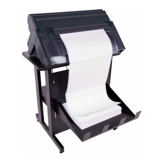
Page 55: Options
Options Option Description Printer Stand An optional stand provides input and output shelves for handling fanfold paper. Second forms tractor An optional second tractor can be installed. In this way it is possible to handle two different types of fanfold paper simultaneously with the printer. Controller Board There are three Controller Board options: 1. - Page 56 Quick Setup Guide...
-
Page 57: Notices
Compuprint advises the customers not to use products for which the compliance to this safety rules are not warranted. Finally seek your dealer or contact a Compuprint office and be sure that are provided you the original consumables. - Page 58 European Union (EU) Conformity Statement Compuprint srl declares that this product is in compliance with the essential requirements and other relevant provisions of Directive 2006/95/EC, 2004/108/EC. Per the applicable requirements of EU directive 98/37/EC (“machines”) sound pressure of the above product (measured according to EN27779) does not exceed 70dBA.
- Page 60 MAN10293.00.00 Printed in Italy MAN10293.00.00...
Need help?
Do you have a question about the 4247 Serial and is the answer not in the manual?
Questions and answers