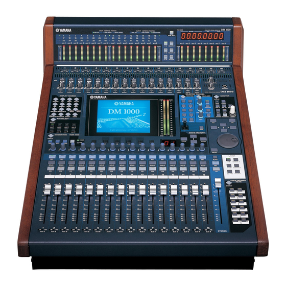
Yamaha DM1000 Owner's Manual
Digital production console
Hide thumbs
Also See for DM1000:
- Service manual (308 pages) ,
- Owner's manual (34 pages) ,
- Manual (30 pages)

Related Manuals for Yamaha DM1000


Summary of Contents for Yamaha DM1000
- Page 1 Owner’s Manual Owner’s Manual Keep This Manual For Future Reference. Keep This Manual For Future Reference.
- Page 2 Compliance with FCC regulations does not guarantee that interference will not occur in all installations. If this product is found to be the source of interference, which can be determined by turning the unit “OFF” and “ON”, please try to eliminate the problem by using one of the following measures: Relocate either this product or the device that is being affected by the interference.
-
Page 3: Important Safety Instructions
The above warning is located on the side of the unit IMPORTANT SAFETY INSTRUCTIONS Read these instructions. 10 Protect the power cord from being walked on or pinched particularly at plugs, convenience Keep these instructions. receptacles, and the point where they exit from Heed all warnings. -
Page 4: Important Information
Failure to do so is a fire and electrical shock hazard. • Do not allow water to enter this unit or allow the unit to become wet. Fire or electrical shock may result. -
Page 5: Operating Notes
Damaged cables may cause fire or electrical shock. • If you know you will not use this unit for a long period of time, such as when going on vaca- tion, remove the power plug from the AC outlet. Leaving it connected is a potential fire haz- ard. -
Page 6: Package Contents
Yamaha Corporation. All other trademarks are the property of their respective holders and are hereby acknowledged. Copyright No part of this unit, its software, or this Owner’s Manual may be reproduced or distributed in any form or by any means without the prior written authorization of Yamaha Corpora- tion. -
Page 7: Conventions Used In This Manual
ENTER and DISPLAY) and buttons that appear on the display pages. References to physical buttons are enclosed in square brackets, for example, “press the [ENTER] button.” Refer- ences to display page buttons are not emphasized, for example, “move the cursor to the ON button.”... -
Page 8: Table Of Contents
Setting Aux Out 1–8 from the Control Surface ....... 92... - Page 9 Control Room Monitor and Solo Setup ....... . . 116...
- Page 10 Using the AD824 ............270 Checking the Battery and the System Version ....... 272 Initializing the DM1000 .
-
Page 11: Welcome
• Faders can set levels for Input Channels, Aux Sends, and Bus Outs. • Rotary Encoders enable you to control panning for each channel, AUX send levels, and various parameters. • Six selectable software layers determine the function of channel faders and Encoders. -
Page 12: Scene Memory
Simultaneous mixing of up to 48 Input Channels. Group multiple channels and pair channels for stereo. • 8 Bus Outs and 8 AUX Sends. Buses 1-8 can be routed to Stereo Buses for use as Group Buses. • Channel library for storing and recalling the channel settings for each Input Channel and Output Channel. -
Page 13: Control Surface & Rear Panel
Control Surface & Rear Panel 2 Control Surface & Rear Panel Control Surface AD Input Section (p. 14) SELECTED CHANNEL Section (p. 19) DISPLAY ACCESS Section (p. 17) +48V +48V +48V +48V +48V +48V +48V +48V +48V +48V +48V +48V... -
Page 14: Ad Input Section
C GAIN controls 1–16 These controls adjust input sensitivity for each AD Input. Input sensitivity is +4 dB to –40 dB when the Pad is on, and –16 dB to –60 dB when the Pad is off. D PEAK indicators 1–16 These indicators light up when the input signal level is 3 dB below clipping. -
Page 15: Channel Strip Section
These are touch-sensitive 100 mm motorized faders. Depending on the button selected in the FADER MODE Section (see page 16), the faders will adjust the input or output level of the selected channels or buses, or adjust the AUX Send level. - Page 16 This button displays an Aux-related page (see page 97). B [AUX 1]–[AUX 8] buttons These buttons select an Aux Send. When you press a button to select an AUX Send, the cor- responding button indicator lights up. ENCODER MODE Section...
-
Page 17: Display Access Section
This button displays a Meter page, which displays Input Channel levels, or Bus Out or Aux Send Out levels (see page 37). H [VIEW] button This button displays a View page, enabling you to view and set mix parameters for a specific channel (see page 69). I [PAIR/GROUP] button This button displays a Pair/Group page, enabling you to pair channels, group multiple fad- ers, or mute channels (see page 74 and 141). -
Page 18: Display Section
This control adjusts the display contrast. D [F1]–[F4] buttons These buttons select a page from a multi-page screen. Selecting a tab at the bottom of the screen using one of these buttons displays the corresponding page. (See page 28 for more information on displaying a page.) -
Page 19: Selected Channel Section
A ROUTING [DISPLAY] button This button displays a Routing page, enabling you to route selected channels to the desired Bus, and adjust the level of the signals routed from Buses 1–8 to the Stereo Bus (see page 68 and 83). -
Page 20: Layer Section
The number of the currently-selected Scene memory is displayed here. B Edit indicator If you adjust a mix parameter after a Scene has been recalled or stored, a dot flashes here. C [STORE] button This button enables you to store the current mix settings (See page 155 for more informa- tion on Scene Memories). -
Page 21: Data Entry Section
B Talkback mic This built-in microphone is used for talkback. C PHONES LEVEL control This control sets the level of the PHONES. (See page 115 for more information on moni- toring through the headphones.) D PHONES jack You can connect a set of stereo headphones to this stereo phone jack. -
Page 22: Monitor Section
These buttons select the Control Room Monitor output signal. When the [2TR D1] button indicator is lit, the signal at the 2TR OUT DIGITAL 1 jack is selected. When the [2TR D2] button indicator is lit, the signal at the 2TR OUT DIGITAL 2 jack is selected. When the [STEREO] button indicator is lit, the Stereo Bus signal is selected. -
Page 23: Rear Panel
The nominal signal level 2 (hot) ranges from –60 dB through +4 dB. B OMNI IN connectors 1–4 These balanced XLR-3-31-type connectors accept line-level signals. The nominal signal level is +4 dB. C OMNI OUT connectors 1–4 2 (hot) -
Page 24: Remote Connector
CAM DA-98HR and other professional video recorders). Use a reverse cable to connect an AD824, and use a straight cable to connect a P2 Protocol device. Use a reverse cable to con- nect two DM1000s to each other. Connecting two DM1000s to each other enables commu- nication via MIDI Protocol and SOLO Logic synchronization. -
Page 25: Power Section
The supplied power cord features a three-pin plug. If the ground terminal of the AC outlet is grounded, then the unit will be grounded sufficiently via the power cord. If the AC outlet does not provide a suitable ground, this screw must be connected to a suitable ground point. -
Page 26: Installing An Optional Card
Chapter 2—Control Surface & Rear Panel Installing an Optional Card Visit the following Yamaha Pro Audio web site to ensure that the card you are installing is supported by the DM1000. Also, verify the number of cards (including other Yamaha or third-party cards) that can be installed in the unit. -
Page 27: Operating Basics
This chapter describes basic operations on the DM1000, including how to use the display and operate the controls on the top panel. About the Display The top panel display indicates various parameters that you must set before you can operate the DM1000. The display indicates the following items: EDIT indicator... -
Page 28: Selecting Display Pages
You can also select a page from a page group as follows: • Selecting the next page in a page group: Press the button you selected in Step 1 repeatedly. This enables you to select a page that has a hidden tab. -
Page 29: Display Interface
Tip: The DM1000 remembers the current page and parameter when you select a new page group. If you return to the previous page group, the DM1000 displays the correct page, with the same parameter selected. You can also select a page by using the controls or buttons on the top panel (see page 250). -
Page 30: Title Edit Window
For certain functions, the DM1000 prompts you for confirmation before executing the functions, as shown here. Move the cursor to YES and press [ENTER] to execute the function, or move the cursor to NO and press [ENTER] to cancel. If you take no action for awhile, the confirmation window closes automatically and the function is not executed. -
Page 31: Selecting Layers
Use the LAYER buttons to select a layer you wish to edit using the channel strip controls. The following table shows the layers that you can access using the LAYER buttons, and the parameters you can control using the channel strips on each layer. -
Page 32: Selecting Channels
GRAB lights up. If the Fader Touch Sense parameter is enabled on the Setup | Prefer2 page (see page 252), operating a fader selects the corresponding channel. The Channel’s ID and Short name appear in the upper-left corner of the display. If the cur- rently-displayed page contains a relevant channel parameter, the cursor moves to that parameter automatically. -
Page 33: Selecting Fader Modes
No operation No operation Note: You cannot select Aux mode while the Master layer is selected. If you switch to the Master layer while the FADER MODE [AUX] indicator is lit, the indicator automatically turns off and the [FADER] indicator lights up. -
Page 34: Selecting Encoder Modes
Chapter 3—Operating Basics Selecting Encoder Modes The function of Encoders (1–16) depends on the selected Layer and Encoder mode. 1 Select a layer that includes the desired channel (see page 31). 2 Press the corresponding ENCODER MODE button to ENCODER MODE select an Encoder mode. -
Page 35: Assigning Parameters To The Encoder Mode [Assign] Button
2 Use the Parameter wheel or press the [INC]/[DEC] buttons to select a param- eter in the right-hand box. A parameter is selected when it appears inside the dotted box. Refer to the next page for a complete list of assignable parameters. - Page 36 Chapter 3—Operating Basics • Assignable Encoder Mode Parameter List Parameters Encoder Operation Push Switch Operation No Assign — — Attenuator Attenuator Display the settings. Input Patch Input Channel patch Insert In Patch Insert In patch Confirm patch selection. Insert Out Patch...
-
Page 37: Metering
• PRE FADER ....Immediately before the fader. • POST FADER ....Immediately after the fader. Tip: If an optional MB1000 Peak Meter Bridge is installed, changes on this page will be reflected on the Input & Output Metering Position parameters on the Peak Meter Bridge. - Page 38 This page displays the Stereo Out or Control Room Monitor output level. Tip: You can also select the CH1-32 page, the CH33-48 page, or the Master page using the LAYER buttons. In this case, if an optional MB1000 Peak Meter Bridge is installed, the Peak Meter Bridge displays the same signal meters in unison with the DM1000 meters.
- Page 39 6 To activate the Peak Hold function, move the cursor to the PEAK HOLD but- ton, then press [ENTER]. The PEAK HOLD button turns on, and the peak level is held on the meters on the page and on the Peak Meter Bridge. To cancel the Peak Hold function, turn the PEAK HOLD button off.
- Page 40 Chapter 3—Operating Basics DM1000—Owner’s Manual...
-
Page 41: Connections And Setup
In this system, the DM1000, with optional AD cards (MY8-AD, MY8-AD96, etc.) installed in Slots 1 and 2, is used as a keyboard mixer or sound re-enforcement mixer. Up to 32 ana- log channels, including Inputs 1–16 and line inputs on the AD cards, are available for mix- ing. - Page 42 In this system, the DM1000, with optional I/O cards (MY8-AT, MY16-AT, MY8-TD, etc.) installed in Slots 1 and 2, is one component in a system that includes a digital MTR, such as a hard disk recorder. This system will support track recording, overdubbing, track bounc- ing, and mixdown.
- Page 43 Slots 1 and 2, is connected to a computer-based DAW (Digital Audio Worksta- tion). The DM1000 can provide audio input and output for the DAW. If you connect the DM1000 and the computer via USB, the DM1000’s Remote function enables you to control the DAW’s locate and transport functions and change the parameters.
-
Page 44: Wordclock Connections And Settings
If you are digitally connecting the DM1000 to other equipment, you must decide which device to use as the wordclock master and which devices to use as slaves, then set up all the devices accordingly. The DM1000 can be used as the wordclock master running at either 44.1 kHz, 48 kHz, 88.2 kHz, or 96 kHz, or slaved to an external wordclock source. - Page 45 Wordclock Connections and Settings If the external devices do not have wordclock in and out connectors, you can use the clock information included in the digital audio signals. In this case, digital audio signals and wordclock signals are transferred via the 2TR OUT DIGITAL and 2TR IN DIGITAL jacks or via the digital I/O cards installed in the rear panel slots.
- Page 46 A usable wordclock signal is present at this input, and it is in sync with the current DM1000 internal clock. No wordclock signal is present at this input. A usable wordclock signal is present at this input, but it is out of sync with the current DM1000 internal clock. This input is the currently-selected wordclock source.
-
Page 47: Input And Output Patching
This section explains how to view the signals patched to Inputs and Outputs and change the assignment. Tip: If the data from a connected instrument fails to be input, or if you are unable to monitor an OMNI OUT, check the I/O patching, as explained below:... - Page 48 3 Press [ENTER] to confirm the change. Tip: • By default, you can also use the Encoders to select Input Channel sources. Rotate the Encoders to display the In Patch/In Patch page and select sources. Press the Encoder push switches to confirm the changes.
- Page 49 • M.MX XXX (“XXX” is a channel name.) ....Surround Monitor Outs 2 Use the cursor buttons to move the cursor to a patch parameter ( ) you wish to change, and rotate the Parameter wheel or press the [INC]/[DEC] buttons to modify the patching.
- Page 50 Chapter 4—Connections and Setup DM1000—Owner’s Manual...
-
Page 51: Analog I/O & Digital I/O
Inputs 1 through 16 feature rotary gain controls that adjust input sensitivity. Input sensitivity ranges from +4 dB to –40 dB when the Pad is on, and from –16 dB to –60 dB when the Pad is off. GAIN • PEAK & SIGNAL Indicators... -
Page 52: Digital Inputs & Outputs
Any signal path can be patched to these digital inputs and outputs. You can also add analog and digital I/Os by installing optional I/O cards in Slots 1 and 2. Digital I/O Connectors • 2TR IN DIGITAL connector These connectors accept signals from a DAT or other 2-track digital recorder or consumer format digital audio device. -
Page 53: Converting Sampling Rates Of Signals Received At 2Tr Digital Inputs
2. These cards support 24-bit/96 kHz in Double Channel mode. (Separate 96 kHz wordclock required.) 3. This card is identical to the MY8-AE96, except that it features a sampling rate converter. See the Yamaha Professional Audio Web site at the following URL for up-to-date news on I/O cards: <http://www.yamahaproaudio.com/>. - Page 54 Note: The sampling rate converter is available only on the Yamaha MY8-AE96S Digital I/O card. If you have installed other types of I/O cards in the slots, or if no cards are installed in the DM1000, the buttons in the SRC sections are disabled.
-
Page 55: Monitoring Digital Input Channel Status
1 Press the DISPLAY ACCESS [UTILITY] button, then press the [F2] button. The Utility | CH Status page appears. On this page, use the following buttons to select a slot or connector for which you want to view the channel status. -
Page 56: Dithering Digital Outputs
On the DM1000, you can dither the 2TR Digital Outputs and Slot Outputs. For example, you can apply dithering to the DM1000 stereo mix data and record to a 16-bit DAT recorder. 1 Press the DISPLAY ACCESS [DIO] button, then press the [F2] button. -
Page 57: Setting The Transfer Format For Higher Sampling Rates
• DOUBLE SPEED In Double Speed mode, digital audio data is received and transmitted at the current higher sampling rate (i.e., 88.2 kHz or 96 kHz). Select this mode if the devices that support the higher sampling rates transmit or receive data. - Page 58 • You cannot select this mode unless the DM1000 is operating at a higher sampling rate. Tip: • The parameter fields display “–” if the corresponding slots contain no I/O cards or if AD/DA cards or other I/O cards that do not allow you to set the transfer format have been installed. DM1000—Owner’s Manual...
-
Page 59: Input Channels
• ATT (Attenuator) This section enables you to attenuate or amplify the level of signals that will be input to the EQ. The attenuator enables you to prevent post-EQ signals from clipping and to correct sig- nal levels that are too low. -
Page 60: Setting The Input Channels From The Display
This section enables you to adjust the pan setting of the signals routed from the Input Chan- nels to the Stereo Bus. You can also apply the pan setting to a pair of Bus channels. If the internal Surround Sound setting is activated, the Surround Pan settings for 3-1, 5.1, and 6.1 channels are available (see page 121). -
Page 61: Delaying Input Channels
When this button is turned on (highlighted), the delay time for each channel in a chan- nel pair can be set simultaneously. When this option is turned off, the delay time can be set for each channel in a channel pair individually. -
Page 62: Gating Input Channels
44.1 kHz, the range is 0 through 984.1 msec.) • If you select the DELAY SCALE meter or feet button, the distance value can be converted to the delay time based on sonic speeds (about 340 m/sec at 15 degrees Celsius). This option is useful if you wish to correct the timing difference between two sound sources that are far apart. -
Page 63: Compressing Input Channels
TYPE This area displays the current gate type (GATE or DUCKING). Note: You cannot change the gate type on this page. To change the gate type, recall a program that uses the desired gate type from the Gate library. Meters These meters indicate the levels of the post-gate signals and the amount of gain reduc- tion. -
Page 64: Attenuating Input Channels
Move the cursor to the knob for the desired Input Channel, then rotate the Parameter wheel to set the amount of attenuation in the range of –96 dB to +12 dB. To reset the attenuation amount to 0 dB, move the cursor to the desired knob, then press the [ENTER] button. - Page 65 Select YES to execute the copy operation. You can also set the amount of attenuation in bits. To set the amount in bits in the range of +2 bits to –24 bits, move the cursor to the desired bit shift parameter below the attenuator knob, then rotate the Parameter wheel.
- Page 66 21.2 Hz to 20.0 kHz (120 steps per 1/12 octave) Gain –18.0 dB to +18.0 dB (0.1 dB steps) 1. The LOW and HIGH GAIN controls function as filter on/off controls when Q is set to HPF or LPF respectively. Tip: •...
-
Page 67: Panning Input Channels
Tip: • You can use the Encoders to change the Input Channel pan settings (see page 71). This is useful if you wish to change the pan settings quickly. You can also use the Joystick in the SELECTED CHANNEL section to change the pan settings, unless the DM1000 is in Sur- round mode. -
Page 68: Routing Input Channels
Chapter 6—Input Channels Routing Input Channels You can route each Input Channel to the Stereo Bus, Bus 1–8, or its own Direct Out. With the default setting, signals are routed only to the Stereo Bus. However, you can patch signals to a single or multiple destinations, if necessary. -
Page 69: Viewing Input Channel Settings
This section enables you to turn the compressor-type dynamics processor on or off and set the parameters. (See page 63 for more information.) INSERT section This section enables you to turn the Insert on or off and patch the Insert In and Out. (See page 112 for more information.) EQ section This section enables you to set various EQ parameters. - Page 70 ■ Viewing the Pan, Fader, and Aux Send Level Settings To display the View | Fader page of a certain Input Channel, use the corresponding [SEL] button or fader to select the desired channel, then press the DISPLAY ACCESS [VIEW] but- ton, then the [F2] button.
-
Page 71: Setting The Input Channels From The Control Surface
“—” appears. Setting the Input Channels from the Control Surface You can use the faders, Encoders, [SEL] buttons, and various buttons and controls in the SELECTED CHANNEL section on the top panel to directly control most parameters for Input Channels. - Page 72 Chapter 6—Input Channels Routing and EQ’ing Input Channels 1 Press the [SEL] button or move the fader for the channel you wish to control. 2 To route each Input Channel, use the following buttons in the SELECTED CHANNEL section: • ROUTING [1]–[8] buttons ....These buttons route the currently-selected Input Channel to a Bus.
-
Page 73: Pairing Input Channels
Attenuators Recall Safe Routing settings To pair channels, or to cancel channel pairs, you can use the [SEL] buttons on the top panel or access the Pair/Group pages. ■ Pairing Channels by Using the [SEL] Buttons 1 While pressing and holding down the [SEL] button for one of the channels you wish to pair, press the [SEL] button for the adjacent channel. - Page 74 Move the cursor to the desired button, then press [ENTER] to confirm the pair. Tip: Pressing and holding down the first [SEL] button of the paired channels and pressing the second [SEL] button cancels the pair. ■ Pairing Input Channels Using the Display 1 Press the [PAIR/GROUP] button repeatedly until the Pair/Grup | Input page appears.
- Page 75 4 To cancel a pair, move the cursor to the desired channel’s STEREO button, then press [ENTER]. Tip: You can also pair or cancel a pair of Output Channels in the same way on the Pair/Group | Output page (see page 87).
-
Page 76: Naming Input Channels
Chapter 6—Input Channels Naming Input Channels By default, Input Channels are named CH1, CH2, etc. You can change these names if nec- essary. For example, it may be helpful for mixdown if you name a particular Input Channel with the type of musical instrument connected to the corresponding input jack. -
Page 77: Using Ms Stereo Microphone
M (Middle) and bi-directional S (Side) microphones. An M microphone picks up main sig- nals, and an S microphone picks up directional signals. These two signals are decoded by calculating a sum (M plus S) and a difference (M minus S), and are recorded to L and R channels. - Page 78 Chapter 6—Input Channels DM1000—Owner’s Manual...
-
Page 79: Bus Outs
This section enables you to switch the metering position of signal levels that are displayed on the Meter page or by the stereo meter to the right of the screen. (See page 37 for more information on selecting the metering position.) Note: By default, the Stereo Out signals are output to OMNI OUT 9–10. -
Page 80: Bus Out 1-8
Tip: You can also pair adjacent odd-even buses (in this order) for stereo operation (see page 87). Note: By default, channels 1–8 and 9–16 of Slots 1 and 2 are patched to the Bus Out 1–8 outputs. However, you can change this patching on the Output Patch page. -
Page 81: Setting The Stereo Out And Bus Out 1-8 From The Display
Setting the Stereo Out and Bus Out 1–8 from the Display To set the Stereo Out and Bus Out 1–8 parameters, you can either move the cursor to the desired parameter on the display and change the value, or operate the desired button or control on the top panel. - Page 82 To set the EQ for the Stereo Out and Bus Out 1–8 EQ, press the EQUALIZER [DISPLAY] button repeatedly to display the EQ | EQ Edit page, and use the [SEL] buttons or faders to select the Stereo Out or Bus Out 1–8.
- Page 83 Routing Bus Out 1–8 Signals to the Stereo Bus You can patch Bus Out 1–8 signals to Outputs and Slots 1/2, as well as to the Stereo Bus. You can adjust the level and pan settings of the signals routed to the Stereo Bus for each bus. This is convenient when you wish to use Bus Outs (1–8) as a Group Bus.
- Page 84 • Stereo Out Fader page This control adjusts the level balance between the L and R channels of the Stereo Out. ON/OFF This button turns the Stereo Out on or off, and links with the [ON] button in the STE- REO section. DM1000—Owner’s Manual...
- Page 85 Fader This fader sets the currently-selected Bus Out (1–8) level, and links with the fader (9–16) in the Master layer. The fader knob is highlighted when the fader is set to 0.0 dB. TO ST PAN This control sets the Bus Out to Stereo Out Pan position for the currently-selected Bus Out (1–8).
-
Page 86: Setting The Stereo Out And Bus Out 1-8 From The Control Surface
To set Bus Out 1–8 levels, press the [MASTER] button in the LAYER section to select the Master layer, then move faders 9–16. At this time, you can turn Bus Out 1–8 on or off using the [ON] 9–16 buttons. -
Page 87: Pairing Buses Or Aux Sends
This button determines whether Aux Sends follow the Input Channel Surround Pan when the DM1000 is in a Surround mode. When this button is turned on, Aux Sends follow the Input Channel Surround Pan. This is useful for feeding Surround signals to external Surround effects processors. -
Page 88: Attenuating Output Signals
Parameter wheel or press the [INC]/[DEC] buttons to set the amount of attenuation. The amount of attenuation can be set from 0 dB to –9 dB. Tip: To reset the attenuation amount of all Output Channels to 0 dB, move the cursor to the INITIALIZE button, then press [ENTER]. DM1000—Owner’s Manual... -
Page 89: Naming The Stereo Out And Bus Outs
Naming the Stereo Out and Bus Outs You can change the default Bus names (BUS1, AUX4, STEREO, etc.). It may be convenient to name the buses “Monitor Out” or “Effect Send,” for example, so that you can easily iden- tify the signal type. - Page 90 Chapter 7—Bus Outs DM1000—Owner’s Manual...
-
Page 91: Aux Sends
Aux Sends, processes them using on-board EQ, compressor, etc., then routes them to the specified internal effects processors, output connectors or I/O card connectors. The DM1000 features eight Aux Sends, which can be used to send signals to the internal and external effects processors and monitors. -
Page 92: Setting Aux Out 1-8 From The Control Surface
To set Aux Out 1–8 levels, press the [MASTER] button in the LAYER section to select the Master layer, then move faders 1–8. At this time, you can turn Aux Out 1–8 on or off using the corresponding [ON] 1–8 buttons. - Page 93 Comp settings To set the Aux Out 1–8 compressors, press the [DYNAMICS] button, then the [F3] button to display the Dynamics | Comp Edit page, and select the desired Aux Out 1–8 by using the corresponding [SEL] buttons or faders.
-
Page 94: Viewing Aux Out Settings
To set the EQ for Aux Out 1–8, press the EQUALIZER [DISPLAY] button repeatedly to dis- play the EQ | EQ Edit page, and use the [SEL] buttons or faders to select Aux Out 1–8. The parameters on this page (and the procedure for setting them) are the same as for Input Channels (see page 65). - Page 95 Setting Aux Out 1–8 from the Display ■ Viewing Faders and On/Off Parameters To display the View | Fader page, use the corresponding [SEL] button or fader to select the desired Aux Out (1–8), then press the DISPLAY ACCESS [VIEW] button, then the [F2] but- ton.
-
Page 96: Setting Aux Send Levels
Setting Aux Send Levels You can adjust the level of signals routed from Input Channels to the corresponding Aux Out (1–8). To do this, you can either use the Encoders on the top panel or set the parameters on the screen. - Page 97 fixed); and Variable (Aux Send levels are variable). • GLOBAL The GLOBAL PRE and POST buttons enable you to set all Input Channels for the selected Aux Send to pre-fader or post-fader simultaneously. Note: In Fixed mode, Aux Send ON/OFF buttons appear instead of the Aux Send rotary con- trols, PRE/POST buttons, and GLOBAL PRE/POST buttons.
- Page 98 Send level rotary controls and PRE/POST buttons. • Variable Mode In this mode, Aux Send levels are variable and the signal source point can be either pre-fader or post-fader. Channel Send level rotary controls and PRE/POST buttons appear on the screen.
- Page 99 Setting Aux Send Levels 4 If you switched to Fixed mode in Step 3, the ON/OFF buttons turn on or off each Input Channel on or off for the currently-selected Aux Send. Note: In Fixed mode, the Aux On/Off parameters for paired Input Channels are not linked to each other.
-
Page 100: Viewing Aux Send Settings For Multiple Channels
Chapter 8—Aux Sends Viewing Aux Send Settings for Multiple Channels You can view and set parameters for all Aux Send 1–8, including setting levels and Pre/Post parameters. This is convenient when you wish to visually check all Aux Send settings or simultaneously adjust the levels of certain channels routed to Aux 1–8. - Page 101 Note: You can switch between Pre and Post only for Aux Sends that are set to Variable mode. The “FIX” indication appears for Aux Sends that are set to Fixed mode, and you cannot switch Pre/Post.
-
Page 102: Panning Aux Sends
5 If necessary, move the cursor to the MODE parameter box and rotate the Parameter wheel to select INDIVIDUAL, GANG, or INV GANG, then press [ENTER]. This Mode setting is independent of the Mode parameter on the Pan page. (See page 67 for more information on Mode options.) DM1000—Owner’s Manual... -
Page 103: Excluding Certain Channels From Aux Sends (Mix Minus)
6 To link the Input Channel Pan setting with the Aux Send Pan setting, move the cursor to the INPUT PAN LINK ON/OFF button, then press [ENTER]. The pan positions on the Pan page are copied to the Aux pan setting, and the pan controls on both pages are linked. -
Page 104: Copying Channel Fader Positions To Aux Sends
1 Press and hold down the copy source layer (LAYER [1-16], [17-32], or [33-48]) button. Note: If you release the button in the LAYER section before you proceed to Step 2, you will be unable to complete the Copy operation. -
Page 105: Input & Output Patching
2TR DIGITAL IN 2 (L/R) 45–48 OMNI IN connectors 1–4 You can change these patches, if you desire. To change input patching, you can either use the Encoders on the top panel or set the parameters on the display. DM1000—Owner’s Manual... - Page 106 Tip: • You can patch an input signal to multiple Input Channels. • You can store the Input Patch settings to the Input Patch library. Refer to Chapter 15 “Librar- ies” on page 165 for more information. • The number of outputs of internal Effects processor 1 varies depending on the selected effect program.
- Page 107 Input Patching Using the Encoders for Input Patching By default, you can also use the Encoders on the top panel to change the Input Patching. 1 Press the ENCODER MODE [ASSIGN] button. The button indicator lights up. By default, you can use the Encoders to change Input Patching while the [ASSIGN] button indicator is lit.
-
Page 108: Output Patching
Chapter 9—Input & Output Patching Output Patching The DM1000’s Stereo Out, Bus Out 1–8, Aux Out 1–8 signals can be patched to any outputs and slot channels. Patch example: Output Patching Stereo Out L OMNI Out connector 1 Stereo Out R... - Page 109 Parameter wheel or press the [INC]/[DEC] buttons to modify the patching. 3 Press [ENTER] to confirm the change. Tip: You can store the Output Patch settings to the Output Patch library. Refer to Chapter 15 “Libraries” on page 165 for more information.
- Page 110 1 Press the DISPLAY ACCESS [OUTPUT PATCH] button repeatedly until the Out Patch | 2TR Out page appears. Signals assigned on the Omni Out page can also be assigned to the 2TR digital outputs. 2 Move the cursor to a patch parameter you wish to change, and rotate the Parameter wheel or press the [INC]/[DEC] buttons to modify the patching.
-
Page 111: Patching Direct Outs
Input Channel 1–48 signals can be directly patched to any outputs or slot outputs, as well as Bus Out 1–8 and Stereo Out. This patching is convenient when you wish to record each Input Channel signal to an individual track on a connected recorder. -
Page 112: Insert Patching
1–8) feature independent Insert Ins and Outs. Inputs, outputs, slot channels, and internal effects processor inputs and outputs can be patched to the Output Channel Insert Ins and Outs. In this way, you can send the signals to external effects processors for processing, or insert internal effects. - Page 113 The Patch Select window appears. Rotate the Parameter wheel or press the cursor buttons to select an item to be patched and press [ENTER]. Then, move the cursor to the YES button and press [ENTER]. The selected item is now patched.
- Page 114 Viewing and Changing Insert In Patch You can view and also change the items patched to the Insert Ins of all Input Channels (or all Output Channels). This is useful when you wish to find out if multiple channels have the same patch.
-
Page 115: 10 Control Room Monitoring
DIGITAL 1 input, and 2TR IN DIGITAL 2 input. If you change the parameter setting on the Monitor | Solo/C-R page (see page 116), you can monitor the OMNI IN signal, instead of the 2TR IN DIGITAL signal, when you press the [2TR D1] or [2TR D2] button. -
Page 116: Control Room Monitor And Solo Setup
• MIX SOLO....In Mix Solo mode, any number of channels can be soloed simultaneously. • LAST SOLO ....In Last Solo mode, only one channel can be soloed at a time by pressing the [SOLO] button. The Solo function that was previ- ously enabled for channels is automatically cancelled. -
Page 117: Solo Trim
Control Room Monitor and Solo Setup SOLO TRIM This parameter enables you to trim the level of the Solo signal in the range of –96 dB to +12 dB. SOLO INTERRUPTION When this parameter is set to Off, soloed channel signals are not fed to the Control Room Monitor outputs. -
Page 118: Using The Control Room Monitor
The channel [SOLO] button indicators and the MONITOR [SOLO] indicator light up. Only the soloed Input Channel signals are fed to the Control Room Monitor outputs. Tip: If the SEL MODE parameter is set to Mix Solo on the Monitor | Solo/C-R page, you can solo multiple Input Channels simultaneously. -
Page 119: Using The Talkback Function
This page contains the following parameters: OUTPUT ASSIGN section The buttons in this section enable you to assign the Talkback mic signal to the desired outputs. (You can select multiple destinations.) TALKBACK DIMMER LEVEL When the Talkback function is active, this parameter determines the amount of attenu- ation applied to the Control Room monitor signals. - Page 120 By default, pressing and releasing the [TALKBACK] button once enables the Talkback func- tion. Press the button again to turn off the function. If you press and hold down the [TALK- BACK] button for more than 300ms, the Talkback function is enabled as long as you hold down the button, and the function is turned off when you release the button.
-
Page 121: 11 Surround Functions
To pan the stereo image, you can use the Parameter wheel, [INC]/[DEC] buttons, or Joystick. You can also store the surround pan settings in a Scene, or record the movement of the sound image to Automixes. In addition to a normal Stereo mode, the DM1000 features the following three Surround modes: •... - Page 122 Track 3 Channel 3 Track 4 Channel 4 8-TRACK DIGITAL Track 5 Digital MTR Channel 5 Track 6 Channel 6 MY8-TD etc. Tip: You can set the surround pan either independently of normal panpots or in unison with them. DM1000—Owner’s Manual...
-
Page 123: Setting Up And Selecting Surround Pan Modes
When this button is turned on, Input Channel panpots and stereo surround panning are linked. Press this button to display the Surr Bus page, which enables you to change the Surround Channel to Bus Out assignment. 2 Move the cursor to the Surround mode button you want to use. - Page 124 5 To link the Input Channel Pan setting with the stereo surround panning, move the cursor to the PAN/SURR LINK button, then press [ENTER]. When the PAN/SURR LINK button is turned on, adjusting the Input Channel pan settings will also change the stereo surround panning accordingly, and vice versa.
- Page 125 SURR/BUS SETUP button, then press [ENTER]. The Setup | Surr Bus page appears. BUS1–BUS8 These parameters select channels to be assigned to the Bus Outs in 3-1, 5.1, and 6.1 Sur- round modes. INIT These buttons reset the channel assignment to the default setting.
-
Page 126: Trajectory Patterns
You can set the surround pan parameters for each Input Channel from the display. 1 Make sure that the DM1000 is in one of the Surround modes, then press the [SEL] button of the channel for which you want to set surround pan. - Page 127 0, the Center signal is fed to only the Left and Right channels. When you set the parameter to 50, the Center signal is fed equally to the Left, Right, and Center channels. This parameter control appears only in 3-1 and 5.1 Surround modes.
- Page 128 • ...... The sound image moves between front and rear. • ...... The sound image moves from front right to rear left. With this pattern, you can also fine-tune the trajectory by using the WIDTH, DEPTH, OFFSET ( ), and OFFSET ( ) parameters.
- Page 129 5 To set the surround pan position, move the cursor to anywhere outside the parameter boxes, then rotate the Parameter wheel. Tip: You can also adjust the pan position using the Encoders if you assign the surround pan parameters to the Encoders.
- Page 130 Trajectory Pattern Note: If you record the movement of the linked channels in an Automix, the sound image moves on both channels when you play the Automix. 8 To list multiple-channel surround pan settings, press the [PAN/SURROUND] button repeatedly until the Pan/Surr | Surr1–16, Surr17–32, or Surr33–48 page appears.
-
Page 131: Surround Monitoring
[GRAB] button enables you to use the Joystick to set the surround pan of the cur- rently-selected Input Channel. Press [ENTER] while the cursor is on the graph to display the Ch Edit page for the selected channel. parameter box This parameter box enables you to move the surround pan setting of the selected chan- nel left and right. - Page 132 Use the MONITOR [MONITOR LEVEL] control on the top panel to adjust the Surround Monitor level. Note: If you turn on the [BUS] button while Surround mode is set to Stereo, the Stereo Bus signals are patched to Surround Monitor.
-
Page 133: Surr. Mode
This parameter selects a surround mode on the surround monitoring system. By default, it is set to the same mode as the SURR. MODE parameter, though you can select any mode that features fewer channels than the current mode. This function is useful when you wish to monitor, for example, a 5.1 surround source through a stereo monitoring system. -
Page 134: Bass Management
0 to +12 dB (1 dB steps) The HPF 1, 2, 3, and LPF 1 & 2 values indicate a cut-off frequency and a filter response. For example, “80-12” means a cutoff frequency of 80 Hz and a filter response of –12 dB/octave. - Page 135 Surround Monitoring The following diagrams show the Bass Management configuration for each Monitor Matrix setting, with Bass Management turned on or off. 6.1 ON 5.1 ON 6.1 OFF 5.1 OFF 3-1 ON ST ON 3-1 OFF ST OFF DM1000—Owner’s Manual...
-
Page 136: Monitor Alignment
Move the cursor to the ATT or DLY parameter box and edit the Attenuator or Delay value. The Attenuator parameters can be set to – dB or from –12.0 dB to +12.0 dB in 0.1 dB steps. The Delay parameters can be set from 0.00 to 30.0 msec in 0.02 msec steps. - Page 137 [SLOT] button. Turning on both buttons 1 and 2 mixes the two slot signals. • C-R TO MONITOR L/R..... When this button is turned on, the Left and Right Surround Monitor Channels are fed to the Con- trol Room Monitors.
- Page 138 The volume setting of the [MONITOR LEVEL] control is calibrated to 85 dB SPL and stored. If you store the cinema standard level in this way, moving the cursor to the SNAP TO SPL85 button and pressing [ENTER] always restores the stored value, even after you adjust the [MONITOR LEVEL] control.
- Page 139 ) for the speaker to which you want to output the Oscillator signal is turned on. If the button is off, move the cursor to the button, then press [ENTER] to turn it on. 3 Move the cursor to the OSC. parameter box, then rotate the Parameter wheel or press the [INC]/[DEC] buttons to select one of the following Oscil- lator waveforms.
- Page 140 6 Press the MONITOR [DISPLAY] button repeatedly until the Monitor | Sur- round page appears. In the SETTING section of the Surround page (see page 137), you can select a Slot Input to be monitored. 7 Move the cursor to the SLOT 1 or 2 button in the SETTING section, then press [ENTER] to select the desired monitoring Slot Input.
-
Page 141: Grouping Channels & Linking Parameters
[ON] buttons for all the grouped channels on or off. A mute group can include On channels and Off channels at the same time, which turn off or on respectively when you press any one of the grouped [ON] buttons. -
Page 142: Using Fader Groups And Mute Groups
These pages enable you to set Mute groups (I–P) for Input Channels 1–32 and 33–48 respectively. - Out Mute page This page enables you to set Mute groups (U–X) for Bus Outs (1–8) and Aux Outs (1–8). • Mute1–32 page DM1000—Owner’s Manual... - Page 143 Example: Input Channels 1–6, and 13–14 have been added to Fader group C. Tip: • If you add one channel from a pair to a group, the pair partner is automatically added to the group. • You can also select a channel on another layer by switching layers.
-
Page 144: Linking Eq And Compressor Parameters
• While a mute group is enabled, you cannot turn a subset of the grouped channels on or off. • If you wish to turn a subset of the grouped channels on or off, first turn off the Enable button, or remove the channels you wish to turn on or off from the group. - Page 145 This page enables you to set Compressor links (m–p) for Bus Outs (1–8) and Aux Outs (1–8). 2 Press the up ( ) or down ( ) cursor button to select a link to which you want to add channels.
- Page 146 EQ link C. Tip: • If you add one channel from a pair to a link, the pair partner is automatically added to the link. • You can also select a channel on another layer by switching layers.
-
Page 147: 13 Internal Effects
Processor inputs and outputs can be patched to various sources. For example, effects pro- cessor inputs can be fed from the Aux Sends and output to Input Channels (effects send/return). Effects processors can also be inserted into Input Channels, Bus Outs, Aux Outs, or the Stereo Out. -
Page 148: Using Effects Processors Via Aux Sends
This button recalls the FX1 Edit–FX4 Edit pages, which enable you to adjust the effect parameters. 3 To select a signal to be input to the effects processor, move the cursor to the desired In parameter box, rotate the Parameter wheel to select a signal from the following options, then press [ENTER]. - Page 149 Tip: • You can also use the Patch Select window to set the OUT parameter boxes, as explained in Step 3. • The number of inputs and outputs available for each effect varies depending on the type of effect programs initially recalled.
-
Page 150: Inserting The Internal Effects Into Channels
You can insert the internal effects into certain Input Channels or Output Channels (Bus Outs 1–8, Aux Outs 1–8, Stereo Out). Note: If effects are inserted in channels, you cannot use those effects via Aux Sends or insert them into other channels. -
Page 151: Editing Effects
This parameter knob enables you to set the balance between wet and dry signals. When the parameter is set to 0%, only the dry signal is heard. When set to 100%, only the wet signal is heard. Turn on the BYPASS button to bypass the currently-selected effects pro- cessor. - Page 152 There are eight meters when Effects processor 1 is selected; two when Effects processors 2–4 are selected. Tip: You can also view the input and output levels of the effects processors on the Meter | Effect 1–4 pages (see page 37).
-
Page 153: About Surround Effects
5.1-channel (AUTO PAN 5.1, CHORUS 5.1, etc.). Surround effects are multi-channel effects that feature up to six inputs and six outputs, and enable you to create the effect of the sound image moving or circling back and forth and left to right, and to process up to six channel input signals simultaneously. - Page 154 Chapter 13—Internal Effects DM1000—Owner’s Manual...
-
Page 155: 14 Scene Memories
Output Patch library numbers Note: • Scenes take a snapshot of Input and Output Patch library numbers that are in use at the time the Scene is stored, but exclude current (edited) Input and Output patching. • If you do not store the edited Input and Output patching to the libraries, recalling a Scene may change the current patching. -
Page 156: About Scene Numbers
DM1000 to their initial or default values, recall Scene memory #0. Also, the Initial Data Nominal check box on the Setup | Prefer1 page (see page 250) enables you to specify whether Input Channel faders are set to either 0 dB or – dB when Scene memory #0 is recalled. -
Page 157: Storing And Recalling Scenes
Scene memory page on the display. Note: • When you store Scenes, make sure that there are no settings in the Edit Buffer that you do not want to store. Make sure that no settings, especially faders, have been adjusted uninten- tionally. - Page 158 Chapter 14—Scene Memories Storing and Recalling Scenes Using the Scene Memory Page On the Scene Memory page, you can store, recall, write-protect, delete, and edit the titles of Scenes. 1 Adjust the mix parameters on the DM1000 to the conditions you wish to store as a Scene.
-
Page 159: Auto Scene Memory Update
You can also move the cursor to the parameter boxes and change the library numbers. Auto Scene Memory Update If the Scene MEM Auto Update check box on the Setup | Prefer1 page (see page 250) is turned on, parameter edits are stored automatically in a Shadow memory, which is avail- able for each Scene. -
Page 160: Fading Scenes
You can specify the time it takes the Input and Output Channel faders to move to their new positions when a Scene is recalled. This is called Fade Time, and it can be set for each chan- nel in the range of 00.0 through 30.0 seconds (in 0.1 second steps). The Fade Time setting is stored in each Scene. - Page 161 Fading Scenes Fading Output Channels To set the Fade Time for the Output Channels (Stereo Out, Bus Outs 1–8, Aux Outs 1–8), press the DISPLAY ACCESS [SCENE] button repeatedly until the Scene | Out Fade page appears. The basic operation is the same as on the In Fade page.
-
Page 162: Recalling Scenes Safely
Chapter 14—Scene Memories Recalling Scenes Safely When a Scene is recalled, all mix parameters are set accordingly. However, in some situa- tions, you can retain the current settings of certain parameters on certain channels by using the Recall Safe function. Recall Safe settings are stored in Scene memories. -
Page 163: Sorting Scenes
Sorting Scenes Sorting Scenes You can sort Scenes in Scene memories. 1 Press the DISPLAY ACCESS [SCENE] button repeatedly until the Scene | Sort page appears. 2 Move the cursor to the SOURCE list ( ) in the left column, and rotate the Parameter wheel or press the [INC]/[DEC] buttons to select the Scene mem- ory you wish to move. - Page 164 Chapter 14—Scene Memories DM1000—Owner’s Manual...
-
Page 165: 15 Libraries
• You can store library data to a computer hard disk using the included Studio Manager soft- ware. Be sure to back up your important data. • You can also store library data to an external MIDI device, such as a MIDI data filer, by using MIDI Bulk Dump (see page 246). - Page 166 STORE This button stores the settings to the selected memory. Before you store the settings, you can enter or edit the title using the Title Edit window. See page 30 for more information on entering characters. You can disable the Title Edit window by turning off the Store Confirmation parameter on the Setup | Prefer1 page.
-
Page 167: Using Libraries
You can recall only the settings for the currently-selected channels from the Channel library. For example, you can recall Input Channel settings to Input Channels, but not to Bus Outs, Aux Sends, or Stereo Out, with the exception that memories #0 and #1 can be recalled to any channels. -
Page 168: Input Patch Library
0 dB (i.e., nominal). Input Patch Library The Input Patch library enables you to store and recall all Input Patch settings. The library contains one preset memory and 32 user (readable & writable) memories. -
Page 169: Output Patch Library
Using Libraries Output Patch Library The Output Patch library enables you to store and recall all Output Patch settings. The library contains one preset memory and 32 user (readable & writable) memories. To access the Output Patch library, press the DISPLAY ACCESS [OUTPUT PATCH] button repeatedly until the Out Patch | Library page appears. - Page 170 TYPE parameter. Move the cursor to this button, then press [ENTER] to display the Effect | FX1 Edit, FX2 Edit, FX3 Edit, or FX4 Edit page to adjust the Effects parameters.
- Page 171 • Modulation-based Effects Preset Name Type Description Chorus CHORUS Chorus Flange FLANGE Flanger Proprietary Yamaha effect that produces a richer and Symphonic SYMPHONIC more complex modulation than normal chorus Phaser PHASER 16-stage stereo phase shifter Auto Pan AUTO PAN Auto-panner...
- Page 172 COMPAND 5.1 1. These effects can be recalled only to Effects processor #1. 2. If these effects types are recalled to Effects processor #1, Effects processors #2 through #4 are disabled. Note: • Effects that include “5.1” in the names are multi-channel Surround effects that support 5.1 channels.
-
Page 173: Bus To Stereo Library
Using Libraries Bus to Stereo Library You can store Bus to Stereo settings (levels and panpots of signals routed from Bus Outs 1–8 to the Stereo Bus). The library contains one preset memory and 32 user (readable & writ- able) memories. -
Page 174: Gate Library
The type (Gate or Ducking) and curve of the currently-selected memory is displayed here. Tip: If you selected an Aux Out (1–8), Bus Out (1–8), or Stereo Out that does not feature a gate, the DM1000 indicates “XXX HAS NO GATE!” (in which XXX represents a signal name). - Page 175 Compressor Library This library enables you to store and recall settings for the compressors on Input Channels, Bus Outs 1–8, Aux Outs 1–8, and Stereo Out. The library contains 36 preset memories and 92 user (readable & writable) memories. Follow the steps below to use the Compressor library.
- Page 176 A variation on preset 19, intended for violas or cellos. A variation on preset 20, intended for string instru- Strings3 COMP ments with a very low range, such as cellos or contra- bass. Compressor for brass sounds with a fast and strong BrassSection COMP attack.
- Page 177 Using Libraries EQ Library This library enables you to store and recall EQ settings for Input Channels, Bus Outs 1–8, Aux Outs 1–8, and Stereo Out. The library contains 40 preset memories and 160 user (read- able & writable) memories.
- Page 178 A variation on preset 18. A. G. Stroke 1 Emphasizes the bright tones of acoustic guitars. A variation on preset 20. You can also use it with an acoustic-electric nylon A. G. Stroke 2 string guitar. A. G. Arpeg. 1 Ideal for arpeggio playing on acoustic guitars.
-
Page 179: Surround Monitor Library
To access the Surround Monitor library, press the MONITOR [DISPLAY] button repeat- edly until the Monitor | Surr Lib page appears. For details on storing and recalling memo- ries, see “General Library Operation” on page 165. DM1000—Owner’s Manual... - Page 180 Chapter 15—Libraries DM1000—Owner’s Manual...
-
Page 181: 16 Automix
You can store up to 16 Automixes in the Automix library. You can also store an Automix or the entire Automix library to an external MIDI device, such as a MIDI data filer, by using MIDI Bulk Dump. -
Page 182: Setting Up For Automix Recording
This section describes the procedure you must perform before you start Automix recording. Selecting the Timecode Source Follow the steps below to select the timecode source and frame rate that the DM1000 uses for the Automix function. 1 Press the DISPLAY ACCESS [SETUP] button repeatedly until the Setup | Time Ref page appears. -
Page 183: Creating A Time Signature Map
• If you select the MIDI CLOCK source, Automix will respond to MIDI Start, Stop, and Con- tinue messages. • An Automix will play back correctly even if the frame rate differs from that used when the Automix was originally recorded. However, an Automix recorded using MIDI Clock and an Automix recorded using other timecode sources are not compatible with one another. -
Page 184: Recording An Automix
Automix, as well as recording the fader, [ON] button, and other controller events real-time. Creating a New Automix Follow the steps below to create a new Automix and select the parameters you want to record. 1 Connect a timecode source to the DM1000. - Page 185 The button indicator lights up. If you turn on the [AUTO] button indicator while the REC button is lit or flashing on the Automix Main page, the [SEL] buttons will allow you to enable or disable the Automix function for each channel, or arm or disarm each channel.
- Page 186 • If you use the AUTO REC button instead of the REC button in Step 1, the AUTO REC button will continue to flash after you stop Automix recording. In this way, you can resume recording when you restart the timecode source.
-
Page 187: Parameter Recording
Recording an Automix Parameter Recording The following table summarizes the parameter recording operation for each parameter available in Automix recording. Parameters Channel OVERWRITE Operation Pair/Group Set Layer to Input, Fader Input mode to Fader, use faders Faders of paired channels and... -
Page 188: Punching In & Out
Chapter 16—Automix Punching In & Out You can modify part of a recorded Automix or add events to an Automix (Punch In & Out). You can punch in and out channels using the [SEL] buttons, or individual parameters using other controls. - Page 189 1. To punch in events by performing this operation, turn on the TOUCH SENSE IN button on the Fader1 or 2 page. 2. To punch out events by performing this operation, turn on the TOUCH SENSE OUT button on the Fader1 or 2 page.
-
Page 190: [Sel] Button Functions While The [Auto] Button Indicator Is On
MOTOR button on the Fader 1 or 2 page (see page 196). You can view fader events on the Fader 1 or 2 page (see page 196), and other events on the corresponding pages. Recorded events of the currently-selected channel are reflected in the SELECTED CHANNEL section controls and displays. -
Page 191: Automix Main Page
The amount of free Automix memory remaining is displayed here in kilobytes, as a per- centage, and by a bar graph. SIZE The size of the current Automix and the size of any Automix data in the undo buffer are displayed here in kilobytes. TIME REFERENCE The timecode source and frame rate specified on the Time Ref page (see page 182) are... - Page 192 Punch in Stop recording If the Fader Edit mode is set to Relative, and the Edit Out mode is set to either Takeover or Off, the fader will remain at a position relative to its position when recording was stopped right through to the end of the Automix.
- Page 193 The IN button enables the Touch Sense function for punch in. The OUT button enables the Touch Sense function for punch out. You can set these buttons individually. If the Fader Touch Sense parameter is set to “Disabled,” on the Setup | Prefer2 page, this section is grayed out.
- Page 194 Tip: • The Undo buffer is cleared when you turn off the power to the DM1000. If you want to save the contents of the Undo buffer, perform the undo operation, then store the Automix. • However, you cannot undo the operations performed on the Event Edit page.
-
Page 195: Automix Memory Page
Automix Memory Page Automix Memory Page The Automix Memory page enables you to store and recall Automixes. The lower half of this page is identical to the Automix Main page. To locate the Automix | Memory page, press the DISPLAY ACCESS [AUTOMIX] button repeatedly until the page appears. -
Page 196: Fader1 &2 Pages
Operation” on page 165. Fader1 &2 pages The Fader1 & 2 pages enable you to edit fader positions while viewing the current fader position and the fader data recorded in the Automix. To locate the Fader1 or 2 page, press the DISPLAY ACCESS [AUTOMIX] button repeatedly until the page appears. - Page 197 The numbered buttons below each fader bar are Edit Safe buttons, which prohibit Auto- mix recording on certain channels. A channel is set to safe and excluded from Automix recording when its button is highlighted. However, you can play existing events and use faders, Encoders, and [ON] buttons on safe channels.
-
Page 198: Editing Events Offline
3 Specify the region of Automix data you want to edit by setting the IN and OUT parameters in the TIME SETTING section. You can also capture the IN and OUT points on-the-fly by moving the cursor to the IN or OUT button and pressing the [ENTER] button. To modify the captured positions, move the cursor to the value you wish to change, and rotate the Parameter wheel or press the [INC]/[DEC] buttons. - Page 199 For example, if eight channels are selected as the copy source and you specify “17” in the CH parameter box, the copy destination will be Channels 17 through 24.
- Page 200 • MOVE TO (MERGE TO) section - TIME This parameter specifies the start point to which the specified data is to be moved or merged. (The number in parentheses on the right indicates the end point of the desti- nation.) You can also capture the start point on-the-fly by moving the cursor to the TO button, then pressing the [ENTER] button to capture the current position.
- Page 201 Parameter events for each internal effects processor Tip: • You can select all parameter buttons simultaneously by moving the cursor to a non-high- lighted button and double-clicking the [ENTER] button. A confirmation window appears. • You can deselect all selected parameter buttons simultaneously by moving the cursor to a highlighted button and double-clicking the [ENTER] button.
- Page 202 Job. Tip: • Move the cursor to the NO button, then press [ENTER] to abort the Job. • To return to the previous page without executing the Job, move the cursor to the button, then press [ENTER]. Event Edit Page The Event Edit page enables you to edit, duplicate, delete events and insert new events.
- Page 203 3 To duplicate or delete events, select an event by moving the triangular icon (® ® ® ® ) to the event in the list, then select the DUPLICATE or DELETE button. 4 To modify the event time, channel or parameter value, move the cursor to a parameter value you wish to change, then rotate the Parameter wheel or press the [INC]/[DEC] buttons.
- Page 204 6 To recall the event at the captured position, move the cursor to the LOCATE button, then press [ENTER]. The event at (or closest to) the captured position is displayed and selected in the event list. 7 To insert a new event, use the Event select buttons to select the type of event that you want to insert.
-
Page 205: 17 Remote Control
(You cannot adjust the DM1000’s parameters unless you select a different layer.) You can assign functions of a target device to the controls on the top panel of the DM1000 by using Remote Layers 1 and 2. The following targets are available for remote control: •... -
Page 206: Pro Tools Remote Layer
Tools. Connections and Configuring Pro Tools Follow the steps below to connect the DM1000 to your computer via the USB port so that you can control Pro Tools from the DM1000. Note: You cannot control Pro Tools via MIDI connections. Be sure to connect your computer via the USB or an optional MY8-mLAN card installed in one of the DM1000 slots. - Page 207 6 Choose Peripherals from the Setups menu to open the Peripherals window. 7 Double-click the MIDI Controllers tab. 8 Refer to the screen below to set the Type, Receive From, Send To, and #Ch’s parameters. The DM1000 can emulate up to two MIDI controllers.
- Page 208 ID. Note: If you select an incorrect port, you will be unable to use the Remote function. Be sure to match the port ID with that specified in the Peripherals window in Pro Tools.
- Page 209 MB1000 meters. • Pressing the [REMOTE 2] button and setting the TARGET parameter to ProTools enables you to control Pro Tools from the Remote Layer 2. In this case, the Remote Layer 1 Target parameter is automatically set to No Assign.
- Page 210 Chapter 17—Remote Control Display While the Pro Tools layer is selected, you can use the [F2]–[F4] buttons as well as the left and right [ ] Tab Scroll buttons to select display modes. You can select the follow- ing display modes using these buttons: ■...
- Page 211 ■ Channel Display mode ( [F3] button) Press the [F3] button to select this display mode, in which the parameter controls for tracks 1–16 are displayed. • Parameter controls 1–16 ....Channel parameter controls, such as channel 1–16 panpots, Send A–E send levels, etc.
- Page 212 Chapter 17—Remote Control ■ Meter Display mode ( [F4] button) Press the [F4] button to select this display mode, in which the level meters for tracks 1–16 are displayed. • Channels 1–16....The channel 1–16 levels or Send levels are displayed.
- Page 213 Pro Tools Remote Layer • [AUX 6] button Press and hold down this button and press the desired [SEL] button to reset the correspond- ing channel fader level. Press and hold down this button and press the desired Encoder push-switch to reset the cor- responding channel panpot to center.
- Page 214 ■ USER DEFINED KEYS section • [1]–[12] buttons You can assign one of 164 parameters to each of these buttons. In particular, if you assign any of 53 Remote Control parameters to these buttons, you can operate the transport sec- tion and select various Pro Tools modes from the DM1000 top panel.
- Page 215 Displays a Group ID (to which each channel belongs) below each channel DAW GROUP STATUS number on a Channel or Meter Display page (in all caps for a main group and in lowercase letters for a sub-group). Pressing the key (to which this function is assigned) enables you to view the DAW MONI STATUS current monitoring mode and the channel strip type.
-
Page 216: Setting Channel Levels
To select a single Pro Tools channel, press the [SEL] button that corresponds to the desired channel. To select multiple Pro Tools channels simultaneously, while holding down one [SEL] but- ton, press the [SEL] buttons of the other channels you wish to add. Press the [SEL] buttons again to cancel the selection. Setting Channel Levels 1 Make sure that the FADER MODE [FADER] indicator is lit steadily. -
Page 217: Muting Channels
Press the [ON] buttons again to unmute channels. The [ON] button indicators of unmuted channels light up. There are two mute modes in Pro Tools: Implicit mute and Explicit mute. You can check the mute mode by viewing the [ON] button indicators. -
Page 218: Setting Send Levels
3 Use the faders, Encoders, and [ON] buttons to control the currently-selected send. For stereo Aux input channels, you can set the left and right panpots individually. To do this, press the ENCODER MODE [PAN] button repeatedly. When the button indicator is lit continuously, you can set the left panpot. - Page 219 1 Press the [F2] button to select Insert Display mode. 2 Press the AUX SELECT [AUX 8] button. The [AUX 8] button indicator flashes. You can now select a channel to which you want to insert plug-ins. 3 Press the [SEL] button of each desired channel.
- Page 220 Most plug-ins feature five or more parameters. To edit the fifth or subsequent parameters, use the Tab Scroll buttons to display the desired parameters and their values in the INSERT ASSIGN/EDIT section. The current page number and the plug-in name appear for a moment immediately after you press the Tab Scroll buttons.
- Page 221 You can bypass plug-ins assigned to Pro Tools channels. Before bypassing plug-ins, you must press the corresponding [SEL] button to select a chan- nel to which the plug-ins have been assigned, then press the [F2] button to select Insert Dis- play mode.
- Page 222 By assigning the DAW SCRUB parameter to one of the User Defined buttons [1]–[12], you can scrub Pro Tools tracks back and forth by turning the Parameter wheel. By assigning the DAW SHUTTLE parameter to one of the User Defined buttons [1]–[12], you can shuttle back and forth by turning the Parameter wheel.
- Page 223 Green Auto off Tip: If you assign the parameter that controls Automation to one of the User Defined buttons, you can control the Automation settings by holding down the programmed User Defined but- ton and pressing the [SEL] button of the target channel. See page 257 for more information on assigning parameters to User Defined buttons.
-
Page 224: Nuendo Remote Layer
■ Configuring the DM1000 1 Refer to page 208 to configure the Setup | MIDI/HOST page. 2 Press the LAYER [REMOTE 1] or [REMOTE 2] button to set the TARGET param- eter to Nuendo. You can now remotely control Nuendo using the selected Remote Layer. -
Page 225: Midi Remote Layer
MIDI Remote Layer MIDI Remote Layer If you select USER DEFINED as the target for Remote Layer 1 or 2, you can remotely control the parameters of external MIDI devices (such as synthesizers and tone generators) by oper- ating the channel Encoders, [ON] buttons, and faders to output various MIDI messages. - Page 226 If the MIDI port is already in use, a confirmation window for changing the assignment appears. Move the cursor to the YES button, then press [ENTER]. Tip: If the REMOTE 2 parameter box is grayed out, proceed to Steps 4 and 5 to set the TARGET parameter, then return to Steps 2 and 3.
- Page 227 MIDI Remote Layer ID, SHORT, LONG These parameters display the channel names. The ID parameter displays the channel ID (RM01–RM16) for the currently-controlled MIDI device. ON section This section displays the type of MIDI messages (in hexadecimal or alphabet) assigned to the [ON] buttons for the currently-selected channels (RM01–RM16).
- Page 228 Chapter 17—Remote Control Assigning MIDI Messages to Channel Controls You can quickly use the MIDI Remote function if you use the factory presets in the banks. However, you can also assign the desired MIDI messages to the faders, [ON] buttons, or Encoders.
- Page 229 FADER section. When you operate the faders, values in the range of 00 to 7F (0–127 in decimal) are output. Tip: If “SW” is not assigned in the DATA parameter boxes of the ON section, the current MIDI messages are output.
- Page 230 • UNLATCH....Pressing and holding down the [ON] buttons transmits On messages, and releasing the [ON] buttons transmits Off mes- sages. Tip: Refer to the diagrams below for information on how the [ON] buttons behave when Latch or Unlatch is selected. ■ When “SW” is assigned:...
-
Page 231: Machine Control Function
REMOTE FUNCTION parameter ( ) to “P2-DFLT.” This page enables you to select the type of signals transmitted or received via the REMOTE connector. See page 270 for more information. Tip: For the REMOTE FUNCTION parameter, you can also select P2-VTR1, P2-VTR2, or P2-VTR3 as a P2 protocol format. - Page 232 • SLOT1......Slot 1 with an MY8-mLAN (mLAN card) installed • REMOTE....... REMOTE connector If USB or SLOT 1 is selected, move the cursor to the adjacent parameter box (on the right), and select one of eight ports. 6 Move the cursor to the DEVICE ID parameter box, then rotate the Parameter wheel to set the DM1000 MMC Device ID to the same ID number as the exter- nal device.
- Page 233 TRACK ARMING section This section controls the tracks on external machines. • 1–24 buttons....These buttons turn external tracks 1–24 on or off, and set or cancel their Record Ready mode. • ALL CLEAR....Turning on this button switches all buttons (1–24) simulta- neously.
- Page 234 Chapter 17—Remote Control DM1000—Owner’s Manual...
-
Page 235: 18 Midi
These messages are used to adjust the Freeze effect and Auto Pan 5.1. • Bulk Dump Messages These messages enable you to store the DM1000’s internal data to a sequencer or MIDI filer. When the DM1000 receives these messages, they overwrite the DM1000 data The DM1000 features the following interface for transmitting and receiving MIDI data. -
Page 236: Midi Port Setup
Note: If the computer is turned on but the USB MIDI application has not been launched, DM1000 performance may be slow. In this case, cancel the assignment of the USB port as the MIDI message transmission port. • REMOTE connector This connector normally enables you to remotely control a Yamaha AD824 or a device that supports Sony P2 protocol, or to make a cascade connection with another DM1000. - Page 237 These parameters enable you to route incoming MIDI data from one port to another without changes. Select a port for reception in the first parameter box, and select a port for transmission in the next parameter box (located to the right of the arrow). If you select USB, specify the port number in the small parameter box adjacent to the port parameter box.
- Page 238 Chapter 18—MIDI Selecting MIDI Messages for Transmission and Reception You can select MIDI messages to be transmitted or received at a port specified in the GEN- ERAL section on the Setup | MIDI/Host page (see page 236). To do so, press the DISPLAY ACCESS [MIDI] button repeatedly until the MIDI | Setup page appears.
-
Page 239: Assigning Scenes To Program Changes For Remote Recall
Scene #0 is assigned to Program Change #100, although you can change these assign- ments. Tip: You can store a Scene to Program Change assignment table to an external device by using MIDI Bulk Dump or included Studio Manager software. -
Page 240: Assigning Parameters To Control Changes For Real-Time Control
[INC]/[DEC] buttons to select Scenes. Tip: • If you assign a Scene to multiple Program Changes, the Program Change with the lowest number becomes effective. • You can initialize the Scene to Program Change assignment table by moving the cursor to the INITIALIZE button, then pressing [ENTER]. - Page 241 Tip: NRPNs are special MIDI messages that combine three different Control Changes. They enable you to control many parameters on a single MIDI Channel. 5 Move the cursor to a parameter box in the No. (CH) column, then rotate the Parameter wheel or press the [INC]/[DEC] buttons to select the Control Changes to which you want to assign parameters.
- Page 242 CHANNEL INPUT1–48 MASTER BUS1–8/AUX1–8/STEREO AUX1 SEND AUX2 SEND AUX3 SEND AUX4 SEND INPUT1–48 AUX5 SEND AUX6 SEND AUX7 SEND AUX8 SEND BUS TO ST BUS1–8 PHASE CHANNEL INPUT1–48 CHANNEL INPUT1–48 INSERT ON MASTER BUS1–8/AUX1–8/STEREO AUX1 SEND AUX2 SEND AUX3 SEND...
- Page 243 Assigning Parameters to Control Changes for Real-time Control HIGH Q LOW F LOW G LOW H G LOW L Q LO-MID F LO-MID G LO-MID H G LO-MID L Q HI-MID F HI-MID INPUT1–48/BUS1–8/AUX1–8/STEREO G HI-MID H G HI-MID L...
- Page 244 PARAM32 H PARAM32 L Parameters that feature a setting range of more than 128 steps (such as Fader and Delay Time parameters) require two or more Control Change messages to specify the values. For example, if you wish to control Fader parameters on certain channels using Control Changes, you must assign the same channel to two Control Change numbers, and select “FADER H”...
- Page 245 “TIME LOW,” “TIME MID,” and “TIME HIGH” for the Control Changes in the parameter boxes in the second (middle) PARAMETER column. Note: Parameters that feature a setting range in excess of 128 steps require an appropriate combination of range parameters for successful MIDI Control Change.
-
Page 246: Controlling Parameters By Using Parameter Changes
MIDI | Setup page are turned off. Transmitting Parameter Settings via MIDI (Bulk Dump) You can back up data stored in the DM1000, such as libraries and Scenes, to an external MIDI device by using MIDI Bulk Dump. In this way, you can later restore previous DM1000 settings by transmitting this MIDI data back to the DM1000. - Page 247 CATEGORY section. This button is used primarily when two DM1000s are connected in cascade. TRANSMIT Move the cursor to this button, then press [ENTER] to transmit data specified in the CATEGORY section to an external MIDI device. INTERVAL This parameter specifies the interval between data packets during bulk transmission in...
- Page 248 Note: Data selected by the SETUPMEM button includes MIDI transmission and reception port settings and message settings. After you store to an external device bulk dump data that has its reception disabled, if the DM1000 later starts to receive this particular data, DM1000 bulk dump reception will be turned off immediately, and the DM1000 will be unable to receive subsequent data.
-
Page 249: 19 Other Functions
) is on, the first four characters of a newly-entered Long name are automatically copied to the Short name. You can reset all port names to their default names by moving the cursor to the INITIALIZE button, then pressing [ENTER]. -
Page 250: Setting Preferences
DISPLAY ACCESS [SETUP] button repeatedly. Prefer1 page This page enables you to set the DM1000 so that when you press a button on the top panel, the DM1000 displays the corresponding display page, and shows or hides confirmation and alarm messages. - Page 251 Pan setting. Otherwise, it enables you to adjust the Surround Pan settings. • Auto EQUALIZER Display If this check box is on, the EQ | EQ Edit page appears automatically when you press an EQ-related button in the SELECTED CHANNEL section.
- Page 252 Chapter 19—Other Functions • Initial Data Nominal If this check box is on, Input Channel faders are set to nominal (0 dB) when you recall Scene • Meter Follow Layer If this check box is on, a connected optional MB1000 Meter Bridge automatically track a layer selection made in the LAYER section on the DM1000.
- Page 253 Channel Copy Parameter This parameter selects the channel parameters to be copied when you assign the Chan- nel Copy function to one of the User Defined buttons (see page 257). You can select multiple options. • ALL.........This button selects all parameters that can be copied. When you turn on this button, all other options are cancelled.
-
Page 254: Timecode Display Relative
Automix | Event Edit page (see page 202). • Link Capture & Locate Memory If this check box is on, the Capture memories on the Automix | Event Edit page are linked to the Locate memories. -
Page 255: Creating A Custom Layer By Combining Channels (User Assignable Layer)
DM1000 channels (excluding the Stereo Out). This custom layer is called “User Assignable layer.” You can use either Remote 1 or Remote 2 for a User Assignable layer. 1 Press the DISPLAY ACCESS [REMOTE] button, then press the [F1] or [F2] but- ton. -
Page 256: Using The Oscillator
Parameter wheel to set the Oscillator level to minimum. Note: Sinewave and pink noise create unusually high sound pressure. Oscillator levels that are too high can damage the speakers. When you use the Oscillator, be sure to set the level to minimum, then raise the level gradually. -
Page 257: Using The User Defined Keys
You can assign any of more than 200 functions to the USER DEFINED KEYS [1]–[12]. KEYS If you assign to one of the buttons (or “keys”) a function that is usually executed on the dis- DISPLAY play pages, you can use the assigned button as a shortcut. - Page 258 • You can store User Defined Keys banks to a computer hard disk using the included Studio Manager software. Be sure to back up important data. • You can also store the assignment data to an external device, such as a MIDI data filer, by using MIDI Bulk Dump (see page 246).
-
Page 259: Using Gpi (General Purpose Interface)
You can configure the GPI so that it will output 8-channel trigger sig- nals when you operate the faders or USER DEFINED KEYS, or so that it will receive 4-chan- nel trigger signals to control the DM1000 parameters. - Page 260 CONTROL port Executes the function. Executes the function. At this point, when the DM1000 receives the trigger signal at the CONTROL port, the selected parameter changes. Tip: Refer to the next page for a complete list of assignable parameters.
- Page 261 Output signals from the CONTROL port At this time, the trigger signal is output from the CONTROL port when you operate the assigned parameters or controls. Tip: Refer to the next page for a complete list of assignable parameters and controls.
- Page 262 • xxx FADER ON .... The trigger signal is transmitted when you raise a fader from – . • xxx FADER OFF... The trigger signal is transmitted when you lower a fader to – . • xxx FADER TALLY ..The trigger signal is transmitted while a fader remains above –...
-
Page 263: Using Operation Lock
To cancel Operation Lock, turn off the OPERATION LOCK button. The Password win- dow appears again. Enter the password and select the OK button. Operation Lock is can- celled. Note: If you forget the password, you cannot cancel Operation Lock. Be sure to write down the password. OPERATION LOCK SAFE section This section enables you to select certain controls on the panel to exclude from Opera- tion Lock. - Page 264 Chapter 19—Other Functions PASSWORD This button enables you to change the current password. Move the cursor to the PASS- WORD button, then press [ENTER]. The Set Password window appears, enabling you to change the password. Enter the current password in the PASSWORD field, and a new password in the NEW PASSWORD field.
-
Page 265: Cascading Consoles
- Fader Return - Fader Edit Mode - Touch Sense In - Touch Sense Out - Overwrite (FADER/CH ON/PAN/EQ/AUX/AUX ON/SURR) Tip: The Solo function is always linked regardless of the status of the Cascade COMM Link check box. DM1000—Owner’s Manual... - Page 266 If you want to use the REMOTE connector to transfer MIDI messages, connect the REMOTE connector of each DM1000 using a 9-pin D-sub reverse cable. If you want to use the MIDI IN and OUT ports, connect MIDI IN on one DM1000 to MIDI out on the other DM1000 using a MIDI cable.
- Page 267 Stereo Bus, and Solo Bus signals via two 8-channel digital I/O cards (such as MY8-AT). Note: Be sure to patch the slave Bus signals to the same Buses on the master unit. Incorrect patching will result in an incorrect cascade connection.
- Page 268 9 Press the DISPLAY ACCESS [SETUP] button repeatedly to display the Setup | MIDI/Host page, then set the Cascade Link parameter to “REMOTE.” After Steps 8 and 9, the slave unit will be able to transmit and receive MIDI messages via the REMOTE connector.
- Page 269 At this point, Bus 1–8, Aux 1–4, and the Stereo Bus on both DM1000s are integrated, and the data is output via Bus Outs 1–8, Aux Outs 1–4, and the Stereo Out on the master unit. If you solo channels on one of the DM1000s, you can monitor the soloed signals via the Control Monitor.
-
Page 270: Using The Ad824
AD824 using a 9-pin D-sub reverse cable. • Connect the outputs of the digital I/O cards on each AD824 to the inputs of the DM1000 I/O card. Connection methods and cables vary depending on the specifications of the devices. The following illustration is an example of a system in which two AD824s are connected via MY8-AE cards. - Page 271 AD824s that have their ID numbers set to 1 through 4. AD824 GAIN/PHANTOM CONTROL section This section enables you to set the AD824 channel 1–8 gain and the Phantom power on or off. • ID #1–#4......These buttons select the AD824s you want to control.
-
Page 272: Checking The Battery And The System Version
ACCESS [UTILITY] button repeatedly. Status If the Status is “Okay,” the battery has sufficient voltage for operation. If the Status is “Voltage low!,” ask your Yamaha dealer to replace the battery as soon as possible. Failure to replace a low battery may result in data loss. -
Page 273: Initializing The Dm1000
Operation Lock password to its initial setting. Follow the steps below. Tip: • If you want to keep the current internal data, be sure to first back up the data using the included Studio Manager software. • You can also store the data to an external MIDI device, such as a MIDI data filer, by using MIDI Bulk Dump (see page 246). -
Page 274: Calibrating The Faders
When calibration is finished, the DM1000 displays a page that enables you to fine-tune the fader position. 3 Follow the instructions on the display and lower all faders to – , then press [ENTER]. 4 Set faders 1–16 to –15 and the Stereo fader to –30, then press [ENTER]. -
Page 275: Appendix A: Parameter Lists
74 Output Fader Group Enable T OutFader Group T 31 EQ Lib. Recall No. XX EQ LibXXX Recall 75 Output MUTE Group Enable U Out Mute Group U 32 Surr Lib. Recall +1 Surr. Lib+1 76 Output MUTE Group Enable V Out Mute Group V 33 Surr Lib. - Page 276 158 DAW SCRUB DAW SCRUB 102 Talkback Assign SLOT2-XX Talkback SLOT2-XX 159 DAW AUDITION DAW AUDITION 103 Talkback Assign OMNI OUT XX Talkback OMNI XX 160 DAW PRE DAW PRE 104 Channel Name ID/Short CH ID/Short 161 DAW IN DAW IN...
-
Page 277: User Defined Keys Initial Assignments
USER DEFINED KEYS Initial Assignments USER DEFINED KEYS Initial Assignments BANK A BANK B BANK C BANK D TITLE Surround Monitor Scene Recall Group Enable Automix Snap to SPL85 Scene 1 Recall IN Fader Group A Automix ENABLE Bass Manage ON... -
Page 278: Input Patch Parameters
Appendix A: Parameter Lists Input Patch Parameters INPUT INSERT IN EFFECT IN CASCADE Port ID Description Port ID Description Port ID Description Port ID Description – NONE – NONE – NONE – NONE AD IN 1 AD IN 1 AUX1... - Page 279 Description Port ID Description FX1-2 Effect1 OUT 2 FX1-2 Effect1 OUT 2 INS CH46 InsertOut-CH46 2D1R 2TR IN Dig.1 R FX1-3 Effect1 OUT 3 FX1-3 Effect1 OUT 3 INS CH47 InsertOut-CH47 2D2L 2TR IN Dig.2 L FX1-4 Effect1 OUT 4...
-
Page 280: Initial Input Patch Settings
Appendix A: Parameter Lists Initial Input Patch Settings CHANNEL EFFECT IN PATCH AUX1 NONE NONE NONE NONE NONE NONE NONE AUX2 AD10 NONE AD11 AUX3 AD12 NONE AD13 AUX4 AD14 NONE AD15 CASCADE IN PATCH AD16 S1-1 BUS1 NONE S1-2... - Page 281 Initial Input Patch Settings CHANNEL NAME CHANNEL ID SHORT LONG CH10 CH10 CH10 CH10 CH11 CH11 CH11 CH11 CH12 CH12 CH12 CH12 CH13 CH13 CH13 CH13 CH14 CH14 CH14 CH14 CH15 CH15 CH15 CH15 CH16 CH16 CH16 CH16 CH17 CH17...
-
Page 282: Output Patch Parameters
InsertOut-CH22 S2-4 Slot2 CH4 IN OMNI8 OMNI OUT 8 INSCH22 InsertOut-CH22 INSCH23 InsertOut-CH23 S2-5 Slot2 CH5 IN 2TD1L 2TR OUT Dig.1 L INSCH23 InsertOut-CH23 INSCH24 InsertOut-CH24 S2-6 Slot2 CH6 IN 2TD1R 2TR OUT Dig.1 R INSCH24 InsertOut-CH24 INSCH25 InsertOut-CH25 S2-7... - Page 283 — — CAS BUS8 Cascade Out Bus8 CAS BUS1 Cascade Out Bus1 — — — — CAS AUX1 Cascade Out Aux1 CAS BUS2 Cascade Out Bus2 — — — — CAS AUX2 Cascade Out Aux2 CAS BUS3 Cascade Out Bus3 —...
-
Page 284: Initial Output Patch Settings
Appendix A: Parameter Lists SLOT, OMNI INSERT IN DIRECT OUT 2TR OUT Digital Source Description Source Description Source Description Source Description CAS AUX8 Cascade Out Aux8 — — — — — — CAS ST_L Cascade STEREO_L — — — —... - Page 285 NONE BUS8 BUS8 BUS8 BUS8 NONE STEREO STEREO NONE NONE NONE NONE NONE NONE NONE NONE NONE NONE NONE NONE NONE NONE NONE NONE NONE NONE NONE NONE NONE NONE NONE NONE ST IN has no DIRECT OUT DM1000—Owner’s Manual...
-
Page 286: Gpi Trigger Source List
Appendix A: Parameter Lists GPI Trigger Source List Source Source Source Source NO ASSIGN CH53 FADER ON 106 CH33 FADER OFF 159 UDEF13 LATCH CH1 FADER ON CH54 FADER ON 107 CH34 FADER OFF 160 UDEF14 LATCH CH2 FADER ON... -
Page 287: User Defined Remote Layer Initial Bank Settings
User Defined Remote Layer Initial Bank Settings User Defined Remote Layer Initial Bank Settings Bank 1 (GM Vol & Pan) Name Data Format Controller Short Long – – – – – – – – – – – – – –... - Page 288 Appendix A: Parameter Lists Bank 2 (GM Vol & Effect 1) Name Data Format Controller Short Long – – – – – – – – – – – – – – – RM01 GM01 GM-CH01 VOL&EFF1 ENCODER 0C ENC END –...
-
Page 289: User Defined Remote Layer Initial Bank Settings
User Defined Remote Layer Initial Bank Settings Bank 3 (XG Vol & Pan) Name Data Format Controller Short Long – – – – – – – – – – – – – – – RM01 XG01 XG-CH01 VOL&PAN ENCODER –... - Page 290 Appendix A: Parameter Lists Bank 4 (Nuendo VST Mixer) Name Data Format Controller Short Long SW END – – – – – – – – – – – – RM01 CH1 VST MIXER CH1 ENCODER 0A ENC END – –...
-
Page 291: Effects Parameters
1. 0.02 ms–2.13 s (fs=44.1 kHz), 0.02 ms–1.96 s (fs=48 kHz), 0.01 ms–1.06 s (fs=88.2 kHz), 0.01 ms–981 ms (fs=96 kHz) 2. 6 ms–46.0 s (fs=44.1 kHz), 5 ms–42.3 s (fs=48 kHz), 3 ms–23.0 s (fs=88.2 kHz), 3 ms–21.1 s (fs=96 kHz) EARLY REF. - Page 292 Appendix A: Parameter Lists GATE REVERB, REVERSE GATE One input, two output early reflections with gate, and early reflections with reverse gate. Parameter Range Description TYPE Type-A, Type-B Type of early reflection simulation ROOMSIZE 0.1–20.0 Reflection spacing LIVENESS 0–10 Early reflections decay characteristics (0 = dead, 10 = live) INI.
-
Page 293: Delay Lcr
Effects Parameters MOD. DELAY One input, two output basic repeat delay with modulation. Parameter Range Description DELAY 0.0–2725.0 ms Delay time Feedback gain (plus values for normal-phase feedback, FB. GAIN –99 to +99% minus values for reverse-phase feedback) HI. RATIO 0.1–1.0... - Page 294 Appendix A: Parameter Lists ECHO Two input, two output stereo delay with crossed feedback loop. Parameter Range Description DELAY L 0.0–1350.0 ms Left channel delay time DELAY R 0.0–1350.0 ms Right channel delay time FB.DLY L 0.0–1350.0 ms Left channel feedback delay time FB.DLY R...
- Page 295 High shelving filter frequency HSH G –12.0 to +12.0 dB High shelving filter gain SYNC OFF, ON Tempo parameter sync on/off NOTE Used in conjunction with TEMPO to determine FREQ. SYMPHONIC Two input, two output symphonic effect. Parameter Range Description FREQ. 0.05–40.00 Hz...
-
Page 296: Auto Pan
Lowest phase-shifted frequency offset PHASE 0.00–354.38 degrees Left and right modulation phase balance STAGE 2, 4, 6, 8, 10, 12, 14, 16 Number of phase shift stages LSH F 21.2 Hz–8.00 kHz Low shelving filter frequency LSH G –12.0 to +12.0 dB Low shelving filter gain... - Page 297 HSH G –12.0 to +12.0 dB High shelving filter gain SYNC OFF, ON Tempo parameter sync on/off NOTE Used in conjunction with TEMPO to determine FREQ. HQ. PITCH One input, two output high-quality pitch shifter. Parameter Range Description PITCH –12 to +12 semitones...
-
Page 298: Dual Pitch
–24 to +24 semitones Channel #1 pitch shift FINE 1 –50 to +50 cents Channel #1 pitch shift fine Channel #1 level (plus values for normal phase, minus values LEVEL 1 –100 to +100% for reverse phase) PAN 1 L63 to R63... - Page 299 Oscillator frequency modulation speed FM DEPTH 0–100% Oscillator frequency modulation depth SYNC OFF, ON Tempo parameter sync on/off NOTE FM Used in conjunction with TEMPO to determine FM FREQ MOD. FILTER Two input, two output modulation filter. Parameter Range Description FREQ. 0.05–40.00 Hz...
-
Page 300: Amp Simulate
LPF, HPF, BPF Filter type OFFSET 0–100 Filter frequency offset RESO. 0–20 Filter resonance LEVEL 0–100 Output Level 1. 6 ms–46.0 s (fs=44.1 kHz), 5 ms–42.3 s (fs=48 kHz), 3 ms–23.0 s (fs=88.2 kHz), 3 ms–21.1 s (fs=96 kHz) DM1000—Owner’s Manual... - Page 301 HSH G –12.0 to +12.0 dB High shelving filter gain 1. 6 ms–46.0 s (fs=44.1 kHz), 5 ms–42.3 s (fs=48 kHz), 3 ms–23.0 s (fs=88.2 kHz), 3 ms–21.1 s (fs=96 kHz) DYNA. PHASER Two input, two output dynamically controlled phaser.
- Page 302 Spread DENSITY 0–100% Reverb density THRU, 21.2 Hz–8.00 kHz High-pass filter cutoff frequency 50.0 Hz–16.0 kHz, THRU Low-pass filter cutoff frequency Reverb and chorus balance (0% = all reverb, 100% = all cho- REV/CHO 0–100% rus) FREQ. 0.05–40.00 Hz Modulation speed AM DEPTH 0–100%...
- Page 303 Spread DENSITY 0–100% Reverb density THRU, 21.2 Hz–8.00 kHz High-pass filter cutoff frequency 50.0 Hz–16.0 kHz, THRU Low-pass filter cutoff frequency Reverb and flange balance (0% = all reverb, 100% = all REV/FLG 0–100% flange) FREQ. 0.05–40.00 Hz Modulation speed DEPTH 0–100%...
- Page 304 Spread DENSITY 0–100% Reverb density THRU, 21.2 Hz–8.00 kHz High-pass filter cutoff frequency 50.0 Hz–16.0 kHz, THRU Low-pass filter cutoff frequency Reverb and symphonic balance (0% = all reverb, 100% = all REV/SYM 0–100% symphonic) FREQ. 0.05–40.00 Hz Modulation speed DEPTH 0–100%...
- Page 305 Tempo parameter sync on/off NOTE Used in conjunction with TEMPO to determine FREQ. 1. L<–>R, L–>R, L<–R, Turn L, Turn R DELAY+ER. One input, two output delay and early reflections effects in parallel. Parameter Range Description DELAY L 0.0–1000.0 ms...
- Page 306 Appendix A: Parameter Lists DELAY->ER. One input, two output delay and early reflections effects in series. Parameter Range Description DELAY L 0.0–1000.0 ms Left channel delay time DELAY R 0.0–1000.0 ms Right channel delay time FB. DLY 0.0–1000.0 ms Feedback delay time Feedback gain (plus values for normal-phase feedback, FB.
- Page 307 Delay high-frequency feedback ratio THRU, 21.2 Hz–8.00 kHz High-pass filter cutoff frequency 50.0 Hz–16.0 kHz, THRU Low-pass filter cutoff frequency DLY.BAL 0–100% Delay and reverb balance (0% = all delay, 100% = all reverb) REV TIME 0.3–99.0 s Reverb time INI. DLY 0.0–500.0 ms...
- Page 308 0.1–1.0 High-frequency feedback ratio FREQ. 0.05–40.00 Hz Modulation speed DEPTH 0–100% Modulation depth Distortion and delay balance (0% = all distortion, 100% = all DLY.BAL 0–100% delayed distortion) SYNC OFF, ON Tempo parameter sync on/off DLY.NOTE Used in conjunction with TEMPO to determine DELAY MOD.NOTE...
- Page 309 PLAY button can be triggered by using MIDI Note on/off MIDI TRG OFF, C1–C6, ALL messages. 1. 0.0–5941.0 ms (fs=44.1 kHz), 0.0 ms–5458.3 ms (fs=48 kHz), 0.0–2970.5 ms (fs=88.2 kHz), 0.0 ms–2729.2 ms (fs=96 kHz) ST REVERB Two input, two output stereo reverb.
- Page 310 Radius of the panning track for reverb 1. When set to NOR, the position can be set by using the Joystick so long as the SELECTED CHANNEL PAN/SURROUND [EFFECT] button’s indicator is on. When set to INV, the Joystick will work inversely.
- Page 311 THRU, 21.2 Hz–8.00 kHz High-pass filter cutoff frequency 50.0 Hz–16.0 kHz, THRU Low-pass filter cutoff frequency • When you press the RESET button, the phase will be initialized to the setting of the OFFSET parameter. CHORUS 5.1 Six input, six output chorus for 5.1 surround.
- Page 312 50.0 Hz–16.0 kHz, THRU Low-pass filter cutoff frequency SYNC OFF, ON Tempo parameter sync on/off NOTE Used in conjunction with TEMPO to determine FREQ. SYMPHO. 5.1 Six input, six output symphonic effect for 5.1 surround. Parameter Range Description FREQ. 0.05–40.00 Hz Modulation speed DEPTH 0–100%...
- Page 313 If this is on, only the mid-frequency band will be output. SOLO HIGH OFF, ON If this is on, only the high-frequency band will be output. 1. 6 ms–46.0 s (fs=44.1 kHz), 5 ms–42.3 s (fs=48 kHz), 3 ms–23.0 s (fs=88.2 kHz), 3 ms–21.1 s (fs=96 kHz) DM1000—Owner’s Manual...
- Page 314 3+2: Key-in’s of L, C, and R, and key-in's of LS and RS, are linked respectively (LFE is independent) 2+2: Key-in’s of L and R, and key-in's of LS and RS, are linked respectively (C and LFE are independent) DM1000—Owner’s Manual...
- Page 315 3+2: Key-in’s of L, C, and R, and key-in's of LS and RS, are linked respectively (LFE is independent) 2+2: Key-in’s of L and R, and key-in's of LS and RS, are linked respectively (C and LFE are independent) DM1000—Owner’s Manual...
-
Page 316: Preset Eq Parameters
Appendix A: Parameter Lists Preset EQ Parameters Parameter Title L-MID H-MID HIGH PEAKING PEAKING PEAKING H.SHELF +3.5 dB –3.5 dB 0.0 dB +4.0 dB Bass Drum 1 100 Hz 265 Hz 1.06 kHz 5.30 kHz — PEAKING PEAKING PEAKING +8.0 dB –7.0 dB... - Page 317 1.32 kHz 4.50 kHz 0.18 — PEAKING PEAKING PEAKING PEAKING +4.5 dB 0.0 dB +4.0 dB +2.0 dB E. G. Crunch 1 140 Hz 1.00 kHz 1.90 kHz 5.60 kHz 0.63 PEAKING PEAKING PEAKING H.SHELF +2.5 dB +1.5 dB +2.5 dB 0.0 dB...
- Page 318 Appendix A: Parameter Lists Parameter Title L-MID H-MID HIGH L.SHELF PEAKING PEAKING PEAKING –0.5 dB 0.0 dB 0.0 dB +2.0 dB A. G. Arpeg. 1 224 Hz 1.00 kHz 4.00 kHz 6.70 kHz — 0.12 L.SHELF PEAKING PEAKING H.SHELF 0.0 dB –5.5 dB...
- Page 319 Preset EQ Parameters Parameter Title L-MID H-MID HIGH PEAKING PEAKING PEAKING PEAKING +3.5 dB –10.0 dB +3.5 dB 0.0 dB Bass Drum 3 118 Hz 315 Hz 4.25 kHz 20.0 kHz L.SHELF PEAKING PEAKING PEAKING 0.0 dB +2.0 dB +3.5 dB 0.0 dB...
-
Page 320: Preset Gate Parameters (Fs = 44.1 Khz)
Appendix A: Parameter Lists Preset Gate Parameters (fs = 44.1 kHz) Title Type Parameter Value Threshold (dB) –26 Range (dB) –56 Gate GATE Attack (ms) Hold (ms) 2.56 Decay (ms) Threshold (dB) –19 Range (dB) –22 Ducking DUCKING Attack (ms) Hold (ms) 1.20 S... - Page 321 Preset Compressor Parameters (fs = 44.1 kHz) Title Type Parameter Value Threshold (dB) –24 Ratio ( :1) Attack (ms) A. Dr. BD COMP Out gain (dB) Knee Release (ms) Threshold (dB) –11 Ratio ( :1) Attack (ms) A. Dr. BD...
- Page 322 Appendix A: Parameter Lists Title Type Parameter Value Threshold (dB) –12 Ratio ( :1) Attack (ms) E. B. Slap COMP Out gain (dB) Knee hard Release (ms) Threshold (dB) –10 Ratio ( :1) Attack (ms) Syn. Bass COMP Out gain (dB)
- Page 323 Preset Compressor Parameters (fs = 44.1 kHz) Title Type Parameter Value Threshold (dB) –17 Ratio ( :1) Attack (ms) Strings3 COMP Out gain (dB) Knee Release (ms) Threshold (dB) –18 Ratio ( :1) Attack (ms) BrassSection COMP Out gain (dB)
- Page 324 Appendix A: Parameter Lists Title Type Parameter Value Threshold (dB) –8 Ratio ( :1) Attack (ms) Solo Vocal2 COMP Out gain (dB) Knee Release (ms) Threshold (dB) –9 Ratio ( :1) Attack (ms) Chorus COMP Out gain (dB) Knee Release (ms) Threshold (dB) –33...
-
Page 325: Appendix B: Specifications
Pad switch 0/20 dB attenuation Gain control 44 dB (–60 to –16), detented LED (red) turns on when post HA level reaches 3 dB below clipping at dig- Peak indicator AD Input (1–16) ital domain LED (green) turns on when post HA level reaches 20 dB below nominal at... - Page 326 On/off — OSCILLATOR Waveform Sine 100 Hz, sine 1 kHz, sine 10 kHz, 400 Hz/1 kHz, pink noise, burst noise Routing BUS1–8, AUX1–8, STEREO L, R STEREO, BUS1–8, AUX1–8, SURROUND MONITOR, CONTROL ROOM, DIRECT OUT 1–48, INSERT OUT (CH1–48, BUS1–8, AUX1–8, STEREO), Output patch MONITOR MATRIX OUT, SOLO OUT, CASCADE OUT (BUS1–8, AUX 1–8,...
- Page 327 6.1 6.1, 6.1 5.1, 6.1 3-1, 6.1 ST, 5.1 5.1, 5.1 3-1, 5.1 ST, Monitor matrix 3-1 3-1, 3-1 ST Bass 5 presets management Monitor ATT (–12.0 dB to 12 dB 0.1 dB step), Delay (0–30.0 msec 0.02 msec step) alignment Bypass On/off 8-in, 8-out (EFFECT1): depends on effects type In/out INTERNAL EFFECTS 2-in, 2-out (EFFECT2–4): depends on effects type...
- Page 328 RACK MOUNT KIT: RK1 1. Total harmonic distortion is measured with a 6 dB/octave filter @ 80 kHz. 2. Hum & Noise are measured with a 6 dB/octave filter @ 12.7 kHz; equivalent to a 20 kHz filter with infinite dB/octave attenuation.
- Page 329 Threshold –54 dB to 0 dB (0.1 dB step) Ratio (x :1) x=1, 1.1, 1.3, 1.5, 1.7, 2, 2.5, 3, 3.5, 4, 5, 6, 8, 10, 20 (15 points) Out gain –18 dB to 0 dB (0.1 dB step) Width 1 dB–90 dB (1 dB step)
-
Page 330: Libraries
(1.23 V) (12.28 V) 1. Sensitivity is the lowest level that will produce an output of +4 dB (1.23 V) or the nominal output level when the unit is set to maximum gain. (All faders and level controls are maximum position.) 2. -
Page 331: Digital Input Spec
Level Connector AES/EBU 24-bit RS422 XLR-3-31 type (Balanced) 2TR IN DIGITAL IEC-60958 24-bit 0.5 Vpp/75 Phono 1. XLR-3-31 type connectors are balanced (1=GND, 2=HOT, 3=COLD). Digital Output Spec Output Format Data length Level Connector XLR-3-32 type AES/EBU RS422 24-bit Professional use... -
Page 332: I/O Slot Spec (1-2)
Appendix B: Specifications I/O Slot Spec (1–2) Each I/O SLOT accepts a digital interface card. SLOT #1 has a serial interface. OUTPUT number of Maker Model Function INPUT Format Resolution Frequency Note Available cards Can handle MY8-AT Digital I/O ADAT 24 bit 44.1/48 kHz... -
Page 333: Remote Port
REMOTE Port REMOTE Port Signal Signal RX+/GND RX–/RX– RTS/RX+ TX–/TX+ CTS/TX– TX+/GND N.C. 1. RS422 (for AD824)/SONY 9 pin protocol (P2) CONTROL Port Signal Signal GPO0 GPO1 GPO2 GPO3 GPO4 GPO5 GPO6 GPO7 GPI0 GPI1 GPI2 GPI3 N.C. N.C. N.C. -
Page 334: Dimensions
Appendix B: Specifications Dimensions Unit: mm DM1000—Owner’s Manual... - Page 335 Specifications and descriptions in this owner’s manual are for information purposes only. Yamaha Corp. reserves the right to change or modify products or specifications at any time without prior notice. Since specifications, equipment or options may not be the same in every locale, please check with your Yamaha dealer.
-
Page 336: Appendix C: Midi
Appendix C: MIDI Appendix C: MIDI Scene Memory to Program Change Table Program Initial User Program Initial User Program Initial User Change # Scene # Scene # Change # Scene # Scene # Change# Scene # Scene # — —... -
Page 337: Initial Parameter To Control Change Table
Initial Parameter to Control Change Table Initial Parameter to Control Change Table CHANNEL1 High High NO ASSIGN FADER L MASTER BUS1 FADER H CHANNEL INPUT1 FADER L MASTER BUS2 FADER H CHANNEL INPUT2 FADER L MASTER BUS3 FADER H CHANNEL... - Page 338 Appendix C: MIDI CHANNEL2 High High NO ASSIGN FADER L MASTER BUS7 FADER H CHANNEL INPUT25 FADER L MASTER BUS8 FADER H CHANNEL INPUT26 NO ASSIGN FADER H CHANNEL INPUT27 BALANCE MASTER STEREO FADER H CHANNEL INPUT28 NO ASSIGN FADER H...
- Page 339 Initial Parameter to Control Change Table CHANNEL3 High High NO ASSIGN FADER L MASTER AUX3 G LOW H INPUT1 FADER L MASTER AUX4 G LOW H INPUT2 NO ASSIGN G LOW H INPUT3 NO ASSIGN G LOW H INPUT4 NO ASSIGN...
- Page 340 Appendix C: MIDI CHANNEL4 High High NO ASSIGN FADER L MASTER AUX7 G LOW H INPUT25 FADER L MASTER AUX8 G LOW H INPUT26 NO ASSIGN G LOW H INPUT27 NO ASSIGN G LOW H INPUT28 NO ASSIGN G LOW H...
- Page 341 Initial Parameter to Control Change Table CHANNEL5 High High NO ASSIGN MASTER BUS7 G LO-MID H INPUT1 MASTER BUS8 G LO-MID H INPUT2 NO ASSIGN G LO-MID H INPUT3 NO ASSIGN G LO-MID H INPUT4 NO ASSIGN G LO-MID H...
- Page 342 Appendix C: MIDI CHANNEL6 High High NO ASSIGN MASTER AUX7 G LO-MID H INPUT25 MASTER AUX8 G LO-MID H INPUT26 NO ASSIGN G LO-MID H INPUT27 NO ASSIGN G LO-MID H INPUT28 NO ASSIGN G LO-MID H INPUT29 F LO-MID...
- Page 343 Initial Parameter to Control Change Table CHANNEL7 High High NO ASSIGN NO ASSIGN G HI-MID H INPUT1 NO ASSIGN G HI-MID H INPUT2 NO ASSIGN G HI-MID H INPUT3 NO ASSIGN G HI-MID H INPUT4 NO ASSIGN G HI-MID H...
- Page 344 Appendix C: MIDI CHANNEL8 High High NO ASSIGN NO ASSIGN G HI-MID H INPUT25 NO ASSIGN G HI-MID H INPUT26 NO ASSIGN G HI-MID H INPUT27 NO ASSIGN G HI-MID H INPUT28 NO ASSIGN G HI-MID H INPUT29 F HI-MID...
- Page 345 Initial Parameter to Control Change Table CHANNEL9 High High NO ASSIGN NO ASSIGN G HIGH H INPUT1 NO ASSIGN G HIGH H INPUT2 NO ASSIGN G HIGH H INPUT3 NO ASSIGN G HIGH H INPUT4 NO ASSIGN G HIGH H...
- Page 346 Appendix C: MIDI CHANNEL10 High High NO ASSIGN NO ASSIGN G HIGH H INPUT25 NO ASSIGN G HIGH H INPUT26 NO ASSIGN G HIGH H INPUT27 NO ASSIGN G HIGH H INPUT28 NO ASSIGN G HIGH H INPUT29 F HIGH...
- Page 347 Initial Parameter to Control Change Table CHANNEL11 High High NO ASSIGN NO ASSIGN ATT H INPUT1 NO ASSIGN ATT H INPUT2 NO ASSIGN ATT H INPUT3 NO ASSIGN ATT H INPUT4 NO ASSIGN ATT H INPUT5 HPF ON INPUT1 ATT H...
- Page 348 Appendix C: MIDI CHANNEL12 High High NO ASSIGN NO ASSIGN ATT H INPUT25 NO ASSIGN ATT H INPUT26 NO ASSIGN ATT H INPUT27 NO ASSIGN ATT H INPUT28 NO ASSIGN ATT H INPUT29 HPF ON INPUT25 ATT H INPUT30 HPF ON...
- Page 349 Initial Parameter to Control Change Table CHANNEL13 High High NO ASSIGN NO ASSIGN SURROUND LFE H INPUT1 NO ASSIGN SURROUND LFE H INPUT2 NO ASSIGN SURROUND LFE H INPUT3 NO ASSIGN SURROUND LFE H INPUT4 NO ASSIGN SURROUND LFE H...
- Page 350 Appendix C: MIDI CHANNEL14 High High NO ASSIGN NO ASSIGN SURROUND LFE H INPUT25 NO ASSIGN SURROUND LFE H INPUT26 NO ASSIGN SURROUND LFE H INPUT27 NO ASSIGN SURROUND LFE H INPUT28 NO ASSIGN SURROUND LFE H INPUT29 SURROUND DIV F...
- Page 351 Initial Parameter to Control Change Table CHANNEL15 High High NO ASSIGN NO ASSIGN SURROUND INPUT1 NO ASSIGN SURROUND INPUT2 NO ASSIGN SURROUND INPUT3 NO ASSIGN SURROUND INPUT4 NO ASSIGN SURROUND INPUT5 SURROUND WIDTH INPUT1 SURROUND INPUT6 SURROUND WIDTH INPUT2 SURROUND...
- Page 352 Appendix C: MIDI CHANNEL16 High High NO ASSIGN NO ASSIGN SURROUND INPUT25 NO ASSIGN SURROUND INPUT26 NO ASSIGN SURROUND INPUT27 NO ASSIGN SURROUND INPUT28 NO ASSIGN SURROUND INPUT29 SURROUND WIDTH INPUT25 SURROUND INPUT30 SURROUND WIDTH INPUT26 SURROUND INPUT31 SURROUND WIDTH...
-
Page 353: Midi Data Format
If [NRPN] is selected, these messages are received if [Control Change Rx] is ON ‘V’ tx/rx User define key & Request and the [Rx CH] matches, and will control the parameter that is specified by the ‘U’ tx/rx User assignable layer & Request four messages NRPN control number (62h, 63h) and Data Entry control num- ‘N’... -
Page 354: Program Change
CHECK SUM = (-sum)&0x7F Reception Reception This message is received if [Bulk RX] is ON and the [Rx CH] matches the device If the automix TIME REFERENCE setting is MIDI CLOCK, this message is used number included in the SUB STATUS. - Page 355 BUFFER, UNDO) DI]-[BULK DUMP] screen. 0mmmmmmm ml A bulk dump is transmitted on the [Rx CH] in response to a bulk dump request. End of exclusive 11110111 F7 The data area is handled by converting seven words of 8-bit data into eight 2.12.2.3 Setup memory bulk dump format...
- Page 356 Appendix C: MIDI 2.12.2.8 User Defined Keys bulk dump request format ‘L’ DATA NAME 01001100 4C The second and third bytes of the DATA NAME indicate the bank number. 00000000 00 b=0-3(bank no.1-4) 0bbbbbbb bb System exclusive message STATUS 11110000 F0 total block number(minimum number is 0) BLOCK INFO.
- Page 357 = ch * 128 + cl COUNT HIGH 0ccccccc ch 2.12.2.16 Equalizer library bulk dump request format COUNT LOW 0ccccccc cl The second and third bytes of the DATA NAME indicate the bank number. (See ‘L’ 01001100 4C above) ‘M’...
- Page 358 Appendix C: MIDI 2.12.2.17 Compressor library bulk dump format ‘1’ 00110001 31 The second and third bytes of the DATA NAME indicate the library number. ‘G’ DATA NAME 01000111 47 0:Library no.1 – 127:Library no.128, 0-127(GATE Library no.1-128), 0mmmmmmm mh 256:CH1 –...
- Page 359 0:Library no.0 – 32:Library no.32, 256:current input patch data, 8192:UNDO Manufacture’s ID number (YAMAHA) ID No. 01000011 43 For reception by the DM1000, only the user area is valid. (1-32, 256, 8192) n=0-15 (Device number=MIDI Channel) SUB STATUS 0010nnnn 2n System exclusive message...
- Page 360 The second and third bytes of the DATA NAME indicate the library number. ‘C’ 0:Library no.0 – 32:Library no.32, 256:current data, 8192:UNDO 01000011 43 For reception by the DM1000, only the user area is valid. (1-32, 256, 8192) ‘9’ 00111001 39 ‘1’...
- Page 361 ‘ ’ 00100000 20 End of exclusive 11110111 F7 ‘8’ 00111000 38 ‘C’ 01000011 43 *) For parameters with a data size of 2 or more, data for that size will be transmitted. ‘9’ 00111001 39 ‘1’ 00110001 31 DM1000—Owner’s Manual...
- Page 362 11110000 F0 Manufacture’s ID number (YAMAHA) ID No. 01000011 43 *) For parameters with a data size of 2 or more, data for that size will be transmitted. n=0-15 (Device number=MIDI Channel) SUB STATUS 0001nnnn 1n MODEL ID (digital mixer)
- Page 363 When this is received, the specified memory/library will be stored/recalled. If n=0-15 (Device number=MIDI Channel) SUB STATUS 0001nnnn 1n this is received from Studio Manager or Cascade Link, the operation will be ex- MODEL ID (digital mixer) GROUP ID 00111110 3E...
- Page 364 Studio Manager or Cascade Link, the operation will be executed, Transmission and then the result of execution will be transmitted as the following parameter In response to a request, this is transmitted with the device number set to the response. [Tx CH].
- Page 365 Reception [Rx CH]. This is received if [Parameter change RX] is ON and the [Rx CH] matches the If [Parameter change ECHO] is ON, this message will be retransmitted without device number included in the SUB STATUS. This is echoed if [Parameter change.
- Page 366 Address will be transmitted on the [Rx CH] channel at 50 msec intervals for a End of exclusive 11110111 F7 duration of 10 seconds. Transmission will be disabled if the power is turned off and on again, or if the function channel PORT setting is changed.
- Page 367 When this is received, data of the specified address is transmitted on the [Rx n=0-15 (Device number=MIDI Channel) SUB STATUS 0011nnnn 3n CH] at intervals of 50 msec as a rule (although this may not be the case if the MODEL ID (digital mixer) GROUP ID 00111110 3E port is being used by other communication), for a period of 10 seconds.
-
Page 368: Appendix D: About Optional Product
Attach the brackets to the meter bridge. Align the holes on the lower part of the meter bridge with the holes on the upper part of the brackets (as shown in the illustration below), then use four 8 mm screws ( ) included in the MB1000 package to affix the brackets to the meter bridge. - Page 369 The button indicator of the currently-selected layer lights up. If you turn on the Meter Follow Layer check box on the Setup | Prefer1 page (see page 250), the layer selection on the meter bridge follows the layer selection on the DM1000.
- Page 370 Appendix D: Options Rack Mounting the MB1000 Using Rack Angle Brackets You can rack mount the MB1000 meter bridge using the rack angle brackets that came with the meter bridge. Detach the MB1000 from the DM1000. Also, remove the SP1000 side panels if they are attached.
-
Page 371: Installing The Sp1000 Side Panels
Installing the SP1000 Side Panels Installing the SP1000 Side Panels The figure below illustrates how to attach the left side panel to the DM1000. Attach the right side panel to the DM1000 in the same way. Rack Mounting the DM1000 Using the RK1 Rack Mount You can rack mount the DM1000 using the optional RK1 Rack Mount Kit. -
Page 372: Index
AUX 1–AUX 8 buttons .......16 Symbols Auto ROUTING Display preference 250 AUX button .........16 ø/INS/DLY | DLY 1-16 page ....61 Auto SOLO Display preference ..251 AUX indicator .......16 ø/INS/DLY | DLY 17-32 page .... 61 Auto update function ......159 AUX SELECT section ......16... - Page 373 Index CATEGORY ........55 DAW ..........224 Effect | P-IN Edit 2 page ....153 Changing names ........249 Nuendo ........224 Effect | P-IN Edit1 page .....153 Channel Copy Parameter Other ........... 224 EFFECT button ........18 preference ......253 Pro tools ........206 Effects Channel faders ........15...
- Page 374 Parameter changes ......246 SLOT 1–2 ........52 Parameters ........241 IEEE1394 ..........53 Program changes ......239 In Patch | Cascade In page ....267 L/R Nominal Pan preference ....251 REMOTE connector ....236 In Patch | CH Name page ....76 LAST SOLO ........116 Scene memory to program In Patch | Effect page ......
- Page 375 Input and Output ......47 SETTING section .......137 Preferences ........250 Input channels ......47 Solo function .......118 Out Patch | 2TR Out page ....110 INPUT PATCH button ..17 SOLO SAFE .........117 Out Patch | CH Name page ....89 Input patching ......105 Solo safe function .......117...
- Page 376 Rotary controls & faders .....29 Setup | Prefer3 page ......250 Routing ..........68 Setup | Remote page ....268 Routing | Bus To St page .....83 Setup | Surr Bus page ......125 Routing | CH1-16 page .......68 Setup | Time Ref page .......182 Rear panel ..........
- Page 377 Monitoring matrix .....131 USB port ........236 Oscillator ........138 User assignable layer ......255 Pan graph ........126 User Def | User Def page ....257 PAN/SURR LINK .......123 USER DEFINED KEYS ...... 21 PAN/SURROUND button ..17 Initial assignments ..... 277 Panning from the display ...126...
-
Page 378: Midi Implementation Chart
:Reset MTC quarter frame message is recognized. Notes *1: Bulk Dump/Request, Parameter Change/Request, and MMC. For MIDI Remote, ALL messages can be transmitted. Mode 1: OMNI ON, POLY Mode 2: OMNI ON, MONO O: Yes Mode 3: OMNI OFF, POLY... - Page 379 SOLO TRIM TALKBACK SOLO L [TALKBACK] SOLO R AD 1-16 METER AUX1-8 AUX1-8 OMNI 1-4 PHONES USE AD IN (1-16) or OMNI IN (1-4) LEVEL SOLO LOGIC AS TALKBACK [PHONES] OUTPUT SOLO BUS1-8 BUS1-8 OMNI 1 BUS1-8 OMNI 2 SURROUND MONITOR...
- Page 380 –120 –100 –100 –130 –110 –110 –140 –120 –120 –150 –130 –130 –160 –140 –140 –170 –150 –150 –180 –160 –160 –190 –170 –170 DSP Noise Floor –200 –180 –180 –210 –190 –190 [0dBu = 0.775Vrms] [0dBFS = Full Scale]...
- Page 381 Niederlassung und bei Yamaha Vertragshändlern in den jeweiligen Bestimmungsländern erhältlich. Pour plus de détails sur les produits, veuillez-vous adresser à Yamaha ou au distributeur le plus proche de vous figurant dans la liste suivante. Para detalles sobre productos, contacte su tienda Yamaha más cercana o el distribuidor autorizado que se lista debajo.
- Page 382 Yamaha Manual Library http://www2.yamaha.co.jp/manual/english/ This document is printed on recycled M.D.G., Pro Audio & Digital Musical Instrument Division, Yamaha Corporation chlorine free (ECF) paper with soy ink. © 2003 Yamaha Corporation WA83970 306IPAP121.1-02B0 Printed in Japan...
Need help?
Do you have a question about the DM1000 and is the answer not in the manual?
Questions and answers