Table of Contents
Advertisement
Advertisement
Table of Contents

Related Manuals for Teltonika FMB1YX


Summary of Contents for Teltonika FMB1YX
- Page 1 FMB1YX User Manual V0.11...
-
Page 2: Table Of Contents
..............17 ECHNICAL NFORMATION ABOUT INTERNAL BATTERY ....................17 LECTRICAL CHARACTERISTICS ................... 19 BSOLUTE AXIMUM ATINGS CONNECTION, PINOUT, ACCESSORIES .................. 20 FMB1YX :..............20 OW TO INSERT CARD INTO DEVICE FMB1YX .............. 21 OW TO ADD ICRO CARD INTO DEVICE FMB1YX .................... - Page 3 5.1.3 Keyword configuration with TCP ................. 36 ........................36 TATUS INFO ........................ 37 ECURITY INFO ......................37 YSTEM SETTINGS GPRS ........................... 40 SMS/C ......................41 ETTINGS GSM O , SIM1 R SIM2 R PERATORS OAMING AND OAMING PERATOR LIST LACKLIST PERATOR LIST 5.7.1...
- Page 4 Supported features on TAVL client application ............ 85 6.5.4 Text messaging ....................85 6.5.5 Destination message ..................85 6.5.6 ETA request message..................85 FMB1YX WITH LV-CAN200 AND ALL-CAN300 CAN ADAPTERS ..........85 LV-CAN200 ALL-CAN30 ............. 85 URPOSE OF DAPTERS LV-CAN200 ALL-CAN300 ..........
- Page 5 8.1.19 btgetlist # ......................102 8.1.20 obdinfo ......................103 8.1.21 faultcodes ......................103 8.1.22 setkey # # ......................103 8.1.23 delkey # # ......................103 8.1.24 bbread #......................103 8.1.25 bbinfo # ......................103 8.1.26 sdformat ......................104 8.1.27 lvcansetprog # ....................104 8.1.28 lvcangetprog ....................
- Page 6 9.2.21 FOTA WEB port (ID=13001) ................113 9.2.22 FOTA WEB Period (min) (ID=13002) ..............114 SMS/C ...................... 114 ALL SETTINGS 9.3.1 SMS data sending settings (ID=3000) ..............114 9.3.2 Data send number (ID=3001) ................114 9.3.3 Authorized phone numbers (ID=4000-4199) ............114 9.3.4 GSM Predefined Numbers (ID=6000-6009) ............
- Page 7 9.6.1.9 Green driving Send SMS to (ID=7034) ................128 9.6.1.10 Green driving SMS text (ID=8034) ................128 9.6.2 Overspeeding scenario parameters ..............129 9.6.2.1 Overspeeding priority (ID=11100) ................129 9.6.2.2 Max allowed Speed (ID=11104) ..................129 9.6.2.3 Overspeeding output control (ID=11103) ..............130 9.6.2.4 Overspeeding Digital output on duration (ID=11101) ............
- Page 8 9.8.1.9 #1 Geozone X2 (ID=20108)................... 147 9.8.1.10 #1 Geozone X1 (ID=20109) ..................148 9.8.1.11 #1 Geozone OverSpeeding (ID=20110) ............... 148 9.8.1.12 #1 Geozone Max allowed speed (ID=20111) ............... 149 9.8.2 Other Geozones ....................149 9.8.2.1 Send sms to #1-5 Geozone (ID=7025-7029), #6-50 Geozone (ID=7071-7115) ....150 9.8.2.2 SMS Text #1-5 Geozone (ID=8025-8029), #6-50 Geozone (ID=8071-8115) ....
- Page 9 9.11.1.9 Authorized devices MAC list (ID=830 - 834) ..............169 9.12 (ID=30000 – 30500) ................. 169 UTTON 9.13 ......................170 PARAMETERS 9.13.1 I/O#1 property parameter priority Ignition (ID=50000) ........170 9.13.2 I/O#1 operand (ID=50001) ................170 9.13.3 I/O#1 High level (ID=50002) ................170 9.13.4 I/O#1 Low level (ID=50003)................
- Page 10 10.4 .................... 197 ONNECTING ROUND FMB1YX INSTALLATION INSTRUCTION ................198 DEBUG MODE ........................ 199 CHANGE LOG ......................... 201...
-
Page 11: Introduction
The device uses SELV limited power source. The nominal voltage is 12 V DC. The allowed range of voltage is 10 V...30 V DC. To avoid mechanical damage, it is advised to transport the FMB1YX device in an impact- proof package. Before usage, the device should be placed so that its LED indicators are visible, which show the status of operation the device is in. -
Page 12: Legal Notice
GSM network to server. This device is perfectly suitable for applications, which need location acquirement of remote objects. Package contents The FMB1YX device is supplied to the customer in a cardboard box containing all the equipment that is necessary for operation. The package contains: FMB1YX device;... -
Page 13: Basic Characteristics
Basic characteristics GSM / GPRS / GNSS features: Teltonika TM2500 quad band module (GSM 850 / 900 / 1800 / 1900 MHz); GPRS Multi-Slot class 12 (Up to 240 kbps); SMS (text, data). Integrated GNSS receiver ... - Page 14 Sending acquired data via GPRS; GPRS and SMS I/O events; Virtual odometer; Jamming detection; Configurable using Secured SMS Commands; Overvoltage protection; Dual SIM switching mode. Table 1. FMB1YX Supply voltage Description Voltage Duration Normal operation 10-30V Unlimited...
-
Page 15: Technical Features
Technical features Table 2. FMB1YX specification Part name Physical specification Technical details Power supply 10...30 V DC Navigation LED 2W Max Modem LED Energy consumption FMB120 Socket Soldered inner socket GPRS: average 141.6 mA r.m.s; Micro USB socket Nominal: average 32.11 mA r.m.s;... - Page 16 Figure 1 FMB120 view & dimensions (tolerance ±2mm) Figure 2 FMB122 and FMB125 view & dimensions (tolerance ±2mm)
-
Page 17: Technical Information About Internal Battery
0.64 – 0.66 0 – 45 battery FMB1YX internal battery is used for detecting external voltage disconnection. CAUTION: RISK OF EXPLOSION IF BATTERY IS REPLACED BY AN INCORRECT TYPE. DISPOSE OF USED BATTERIES ACCORDING TO THE INSTRUCTIONS. Battery Disposal instructions: Battery should not be disposed of with general household waste. - Page 18 VALUE Min. Typ. Max. Unit CHARACTERISTIC DESCRIPTION Input Voltage threshold (DIN2) Analog Input: Input Voltage (Recommended Operating Conditions), Range 1 Input resistance, Range 1 kΩ Measurement error on 12V, Range 1 Additional error on 12 V, Range 1 Measurement error on 30 V, Range 1 0,33 Additional error on 30 V, Range 1 Input Voltage (Recommended Operating Conditions),...
-
Page 19: Absolute Maximum Ratings
Absolute Maximum Ratings Table 5. FMB1YX absolute maximum ratings VALUE Min. Typ. Max. Unit CHARACTERISTIC DESCRIPTION Supply Voltage (Absolute Maximum Ratings) Drain-Source clamp threshold voltage (Absolute Maximum Ratings), = 2mA drain Digital Input Voltage (Absolute Maximum Ratings) Analog Input Voltage (Absolute Maximum Ratings) -
Page 20: Connection, Pinout, Accessories
3 CONNECTION, PINOUT, ACCESSORIES How to insert SIM card into FMB1YX device Remove FMB1YX cover Insert SIM cards as shown. SIM SLOT 1 is closer to PCB, SIM SLOT 2 is the upper one Attach cover Device is ready ... -
Page 21: How To Add Microsd Card Into Fmb1Yx Device
How to add MicroSD card into FMB1YX device ② Open Push MicroSD MicroSD card card lock case locker ③ ④ Correctly Close microSD insert microSD card card locker into slot ⑤ Push microSD card lock case to locked position Installing FMB1YX drivers Table 6. - Page 22 Installing drivers: Extract and run MS_USB_ComPort_Driver_exe_v1.1032.3. This driver is used to detect FMB1YX device connected to the computer. Click 'Next' in driver installation window (figures below): Figure 3 Driver installation window This will launch device driver installation wizard. In the following window click ‘Install’...
-
Page 23: Socket Pinout
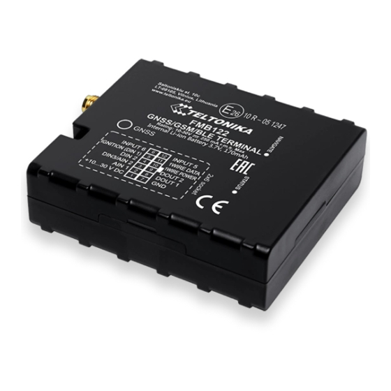
Figure 5 Driver installation window You have now installed drivers for FMB1YX device successfully. FMB120 and FMB122 2x6 socket pinout INPUT 6 12 INPUT 5 DIN 1 11 1WIRE DATA DIN 2 10 1WIRE POWER DIN3/AIN2 9 DOUT2 AIN 1 8 DOUT1 VCC (10…30)V DC(+) -
Page 24: Socket Pinout
INPUT 5 RX EXT (LVCAN - RX) FMB125 2x6 socket pinout INPUT 6 INPUT 5 DIN 1 1WIRE DATA RS232 – TX RS485 – B RS232 – RX RS485 – A AIN 1 DOUT1 VCC (10…30)V DC(+) GND(VCC(-10…-30)V DC)(-) Figure 7 FMB125 2x6 socket pinout Table 8. -
Page 25: Accessories
Accessories Note: Accessories are not included in device package, please order them separately. Table 9. FMB1YX accessories description and connection schemes Accessories Accessories connection schemes Description Digital thermometer DS1820 and TTJ100 connection scheme with 1 – Wire devices FMB120 and FMB122... - Page 26 It is possible to connect FMB1YX Analog input to it (if sensor returns analogue signal proportional to fuel level). After the connection to the tank fuel level sensor, calibration is needed.
- Page 27 Accessories Accessories connection schemes Description Alarm buttons, door sensors, ignition, etc. return two states: high or low voltage. FMB1YX Digital inputs are used to read this information. In cases when sensor Inverting relay connection FMB1YX output signal is negative, an...
-
Page 28: Navigate Led
4 OPERATIONAL BASICS Operational principals FMB1YX module is designed to acquire records and send them to the server. Records contain GNSS data and I/O information. Module uses GNSS receiver to acquire GNSS data and is powered with three data acquiring methods: time-based, distance-based and angle-based. Note,... -
Page 29: Sleep Modes
After timeout is reached and all conditions for GPS sleep mode are met, device goes to sleep mode. While in GPS sleep mode, FMB1YX turns GPS module off and it is still making new periodic records. As a result power usage decreases, in turn saving vehicle battery. -
Page 30: Online Deep Sleep Mode
It keeps adding these intervals until it is time to make a record, then FMB1YX records its location and adds odometer value, which is equal to the sum of all distances, measured every second. The are two odometers I/O elements: Total odometer and Trip odometer. -
Page 31: Features
To save GPRS traffic ECO driving/Green driving event will be generated (included into records) only when FMB1YX measured values are higher than those set in configuration, without additional I/O settings. To prevent generating false events, harsh acceleration and harsh braking is monitored only... -
Page 32: Overspeeding Scenario
PLEASE NOTE that Eco Driving functionality generally is dependent on accelerometer. Auto calibration must be done before using ECO driving scenario. All information about auto calibration descrybed in 5.9.1.2 chapter. 4.4.2 OverSpeeding Scenario. Helps to prevent from exceeding fixed speed and inspects driver if needed. Digital output can be controlled by scenario for user needs, to manage buzzer, LED, etc. -
Page 33: Ibutton Read Notification
If Crash trace is enabled FMB1YX will collect acceleration data every 40 msec. Buffer is big enough to hold data for 5 seconds and on Crash Event detection, records will be generated from this buffer, following these conditions: ... -
Page 34: Auto Geofence
It can be configured to acquire and send data to server. If device is not able to send data to server, GSM is not available FMB1YX will start storing records to flash memory. It is possible to store up to 192 000 data records with 128 Mb SD memory card (when 100 Mb are used for store records). - Page 35 Connect button located in Online menu part. FMB1YX has one user editable profile, which can be loaded from device, and saved. User can also revert to default settings, by pressing Reset to defaults button. After any modification of configuration settings it has to be saved to FMB1YX device, otherwise it will not be written to device.
-
Page 36: Main Buttons Description
If device is locked, keyword cannot be changed with TCP configuration. Status info Status info monitoring FMB1YX real time information in 5 different positions: Device info, GNSS info, GSM info, OBD/ CAN adapter info and I/O info. All this information can be saved into .HTML format with a button whitch is in device info table top right corner. -
Page 37: Security Info
SMS count: how much FMB1YX received SMS and how much SMS was send from device. In OBD info user can see main information from OBD (if device connected to vehicle with OBD II Bluetooth dongle adapter): vehicle VIN code and used OBD protocol. - Page 38 (10 V range for now works same as 30 V range). Time synchronization settings, where user can choose from what source (or sources) FMB1YX time will be synchronized. User has choice to use only one synchronization source by GNSS. When selected synchronization from NTP, time will be synchronized from NTP server and from GNSS.
- Page 39 Figure 12 System settings configuration In GNSS source Settings user can configure which GNSS system or systems to use. User has choice to use only one system of GPS, Glonass, Galileo or Beidou. Also it is able to choose two or three systems together. One exception is that you can not combine Beidou and Glonass systems together.
-
Page 40: Gprs
AVL application. Activate Data Link Timeout is used to set timeout of link between FMB1YX and AVL application termination. If FMB1YX has already sent all records it waits for new records before closing link (except Deep Sleep mode, more indoemation in Deep Sleep mode chapter). -
Page 41: Sms/Call Settings
Essential fields in ‘SMS’ part is ‘Login’ and ‘Password’. The login and password are used with every SMS sent to FMB1YX. If login and password are not set, in every SMS sent to FMB1YX device two spaces before command have to be used (<space><space><command>). - Page 42 SMS login and password and authorized number list are used to protect FMB1YX module from unauthorized access. Module accepts messages only from a list of authorized numbers and with proper module login and password. Phone numbers have to be written in international standard, with using “+” or without using it (in both cases number will be recognized).
-
Page 43: Gsm Operators , Sim1 Roaming And Sim2 Roaming / Home Operator List , Blacklist Operator
Any not written operator in roaming operator list (not home operator) will be recognized as unknown operator and FMB1YX will work in Unknown mode (make sure it is configured to allow data sending – GPRS context is enabled). -
Page 44: List
5.7.1 Dual SIM FMB1YX have possibility to have inserted in them two SIM cards. GPRS settings and Roaming Operators can be configurd separate for SIM1 and SIM2. In SIM2 Roaming/ Home operator list home operator must be added to the any part of the list that functionality works correctly. - Page 45 Figure 18 Dual SIM functionality diagram.
-
Page 46: Data Acquisition Mode Settings
Vehicle moving or stop state is defined by Stop Detection Source parameter. There are 4 ways for FMB1YX to switch between Vehicle on Stop and Vehicle Moving modes, see section 5.4 , Table 12. Object Motion Detection Settings. - Page 47 ‘Min Saved Records’ defines minimum number of coordinates and I/O data that should be transferred with one connection to server. If FMB1YX does not have enough coordinates to send to server, it will check again after time interval defined in ‘Sending Period’.
-
Page 48: Features Settings
Min. time period Distance based data acquiring (Min. distance) – records are being acquired when the distance between previous coordinate and current position is greater than defined parameter value. Entering zero disables data acquisition depending on distance. Min. distance Angle based data acquiring (Min. angle) – records are being acquired when angle difference between last recorded coordinate and current position is greater than defined value. -
Page 49: Green Driving
Figure 21 Scenarios configuration 5.9.1 Green Driving When vehicle exceeds on of Max Acceleration, Max Braking or Max Cornering parameters value, scenario is activated, record will be generated and digital output status will be changed to 1 (if configured). You can configure all three parameters in m/s (meter per second squered) units. -
Page 50: Data Output
If any of three cases are satisfied event is generated. Record is saved and sent to server (FMB1YX must be configured properly). Event value is multiplied by 10 before sending/saving record to get more precision when displaying data*. -
Page 51: Over Speeding
5.9.2 Over Speeding When vecicle speed exeeds configured max speed value scenario is activated, record will be generated and digital output status will be changed to 1 (if configured). Scenario is activated until current speed decreases below parameter value. Figure 23 Over Speeding configuration parameters for FMB120 and FMB122 5.9.3 Jamming When jamming is detected scenario is activated, record will be generated and digital... -
Page 52: Use Authorized Numbers To Control Dout Via Call
Figure 25 DOUT control via call configuration parameters for FMB120 and FMB122 Call control functionality When FMB1YX is configured to control DOUT1/DOUT2 device waits incoming call from configured secure number. If call is received FMB1YX turns on DOUT1/DOUT2 for user defined Duration timeout (s). If Duration timeout set to „0“(s), DOUT1/DOUT2 will be OFF. -
Page 53: Ibutton Read Notification
2. When speed are higher than highway fuel consumption speed, we add for highway fuel consumption x % of highway fuel consumption every y km/h, by default FMB1YX add 20% every 50 km/h. It means that fuel consumption is (1.2 * Highway Fuel Consumption) on 140 km/h speed, (1.4 * Highway Fuel Consumption) on 190 km/h speed. -
Page 54: Excessive Idling
1. Ignition (configured Ignition Source) is OFF. 2. Activation Timeout (set in Towing detection features) is reached. When Activation Timeout is reached and Ignition is still in OFF state, FMB1YX monitors accelerometer data. If Acceleration or Angle value reaches configured threshold for configured Duration (in ms), check Ignition state. -
Page 55: Crash Detection
Threshold and duration values are set depending of accident power which you want to detect. FMB1YX can detect a slight tapping on the device (Threshold=100mg, Duration=1ms) or can detect severe accident (Threshold=4000mg, Duration=5ms). -
Page 56: Dout On/Off Duration
Figure 32 example of Crash Trace logic Figure 33 Crash detection configuration 5.11 DOUT ON/OFF Duration In all scenarios that control Digital Output, Digital Output can be controlled independent from scenario. DOUT ON Duration parameter shows for how long DOUT is set on after scenario is activated and DOUT OFF Duration parameter shows how long DOUT is set off after DOUT ON duration ends. -
Page 57: Dout Control Depending On Functionality Priority
period continues until scenario turns off. DOUT ON and DOUT OFF duration parameters must be configured in ms. 5.12 DOUT control depending on functionality priority All DOUT control functionalities now have their own priority (non-configurable). Depending on priority DOUT control may be overtaken by higher priority functionality without finishing previous scenario. -
Page 58: Manual Geofence
AutoGeofence will be created around vehicle’s last position with set Radius value. Figure 34 Auto Geofence configuration parameters for FMB120 and FMB122 5.14 Manual Geofence FMB1YX configurable Geofence zones and it can generate an event when defined Geofence zone border is crossed. -
Page 59: Trip \ Odometer
Generate event (On entrance, On exit, On Both) – choose when record will be generated. Eventual records – when disabled scenario status value will be appeared in each AVL record, and when enabled scenario status value will be appended only to eventual records. OverSpeeding –... -
Page 60: Advanced Trip Settings
Start Speed (km/h) – GPS speed has to be greater than the specified Start Speed in order to detect Trip Start. Ignition OFF Timeout (s) – timeout to wait if ignition (configured ignition source) was off, to detect Trip stop. Distance counting mode –... -
Page 61: Odometer
ID. iButton ID is saved and sent to server with every record. If new iButton is attached during the trip, FMB1YX remembers new iButton ID. FMB1YX forgets iButton ID after ignition is off and trip ignition off timeout is reached. -
Page 62: Bluetooth
Odometer Value –sets starting total odometer value. Figure 40 Odometer configuration 5.16 Bluetooth Figure 41 Bluetooth general functionality 5.16.1 General functionality General functionality configures Bluetooth to work in slave mode. This mode allows any external device to connect to FMB1YX. - Page 63 5. Local PIN parameter lets user to configure Bluetooth PIN of FMB1YX device. FMB1YX Bluetooth has several different security modes: PIN only – while external device trying to connect to FMB1YX only Local PIN will be reacquired to complete connection.
-
Page 64: How To Connect Bluetooth Hands Free Adapter To Fmb Device
External Name parameter works as substring, this allows user to enter part of the full external device name. For example, if external device name is "HandsFreeHeadset" and user enters "HandsFree" in External Name parameter window then FMB1YX will be allowed to connect to external device named "HandsFreeHeadset". - Page 65 Figure 43 1- Bluetooth settings; 2 - Enable Bluetooth; 3 - Bluetooth local name; 4 - Bluetooth security mode; 5 - Hands Free connection mode; 6 - External Bluetooth device name; 7 - Authorized Devices MAC List; When device configuration is loaded press „Bluetooth“ settings (Figure 43 1 position).
-
Page 66: Connecting Bluetooth Hands Free Adapter
Now we need to send command to FMB1YX from Bluetooth terminal, type: .log:1 Device will respond Debug enabled and FMB1YX log will how up. Do not forget to start save log file to mobile phone. Hands Free device Bluetooth connection pairing instructions depends on specific model. -
Page 67: Device Debug Over Android Smartphone
5.16.4 Device debug over Android smartphone Scan for visible BT devices using your Android smartphone and connect to your FMB device. Default FMB BT name: FMB1YX_last_7_imei_digits Default PIN code: 5555 Download “Bluetooth Terminal” application. You can use link or QR code shown here: https://play.google.com/store/apps/details?id=com.hatfl abs.btt ... -
Page 68: How To Connect Obd Ii Bluetooth Dongle To Fmb Device
(My Files/Bluetooth Terminal), select log files and press button Share via Email and send them to the Teltonika support. In order to pair FMB device with Android smartphone, make sure that BT radio is enabled (visible) in device configuration. It can be checked via SMS command too: getparam 800 The answer has to be 2, which means “Enabled and visible”. - Page 69 Launch FMB Configurator and connect to device as shown in Figure 45 below. Figure 45 FMB1YX configurator connected devices window After successful connection to device wait few moments while device load current configuration, then go to Bluetooth section that visible at Figure 46.
-
Page 70: Connecting To Bluetooth Obd Ii Dongle
When device configuration is loaded press „Bluetooth“ settings (Figure 46 1 position). Turn on BT Radio by pressing „Enable (visible)“ (Figure 46 2 position). “Local name” (Figure 46 3 position) automatically will be “FMB1YX_last 7 imei digits”, you can leave it or type your own name. -
Page 71: Supported Bluetooth Obd Ii Dongles
This event can be triggered by every I/O element. Then any of the I/O elements is triggered, FMB1YX sends a configured SMS message to a defined phone number. If SMS events is activated, but there are no numbers defined in GSM... - Page 72 The sent SMS messages format is according to: “Date Time Current Coordinate Event Text” For example, if FMB1YX is configured to send an SMS, when Ignition reaches High level, with priority High and configured to generate event on both range enter and exit (figure 50), then the sent SMS is: “2017/06/13 13:52:18 Lon:25.255537 Lat:54.667193 Ignition 1”...
-
Page 73: Ibutton List
External Voltage, Speed, Battery Voltage and Battery Current. Priority (AVL packet priority) can be Low, High or Panic. All records made by FMB1YX are regular. Regular packets are sent as Low priority records. When low priority event is triggered, FMB1YX makes additional record with indication that the reason for that was I/O element change (depends from Operand configuration). -
Page 74: Operand On Entrance
Figure 52 On Exit operand logic 5.19.2 Operand On Entrance Record is generated when actual value input increases or decreases and becomes between high and low level values. Current value >= Low level Generate record Current value <= High level Figure 53 On Entrance operand logic 5.19.3 Operand On Both Record is generated by both (On Exit and On Entrance) operands logic at same time. -
Page 75: Operand On Hysteresis
5.19.5 Operand On Hysteresis Record is generated when actual value input inceases from lower than low value to higher than high level value or decreasing from higher than high level to lower than low level. Figure 56 Hysteresis operand logic 5.19.6 Operand On Change Record is generated when value changes. -
Page 76: Obd Ii (Bluetooth) And Lvcan I/O Elements
In OBD II (Bluetooth) column are shown I/O elements which information can be obtained from OBD II Bluetooth dongle connected to FMB1YX device and in LVCAN column are shown I/O elements whitch information can be obtained from LV-CAN200 or ALL-CAN300 connected to FMB1YX device. -
Page 77: Rs232 Working Mode
RS232 working mode 5.19.10.2 RS232 support several modes: Log Mode – suitable for debugging/logging; NMEA – NMEA logs are sent via RS232 or RS485; LLS – LLS sensors support; LCD – external LCD support; RFID HID – RFID card reader support; ... - Page 78 Table 14. Default Baudrate and Parity by RS232/RS485 working Mode Mode RS232 default Baudrate RS485 default Baudrate Default Parity (RS232 only) Log Mode 115200 115200 None NMEA 115200 115200 None 19200 19200 None 57600 None RFID HID 57600 None RFID MF7 9600 None Garmin FMI...
- Page 79 TCP Binary – for routing any binary input data from external device to server. RS485 Baudrate 5.19.10.7 Every RS485 mode support different baudrates, but each mode has its own default baudrate value. Default baudrate values for each RS485 working mode are provided in table 14. Figure 64 RS485 configurable parameters RS485 LLS Sensors 5.19.10.8...
- Page 80 When activated RS485 driver chip draws constant 30mA current. When Entering Sleep or Deep sleep, Chip will be powered off too. FMB125 RS485 Pins connection diagram are shown on the Figure 66: Figure 66 connection block diagram RS485 modes In Configurator windows select RS232/RS485 window where is RS485 Settings (more information about available RS232/RS485 parameters configuration in 5.19.10 FMB125 RS232\RS485 parameters configuration...
- Page 81 6.2.3 RS485 receive (LLS) mode The mode supports up to five LLS fuel level sensors. Baud rate must be 19200. LLS have receiver id. LLS mode configuration shown in Figure 69. 6.2.4 RS485 TCP (ASCII, Binary) mode In TCP ASCII mode link with external device using text messages can be established.
- Page 82 Figure 72 RS232 LCD Mode configuration 6.4.2 RS232 RFID HID/RFID MF7 mode The difference between RFID Mode and RFID MF7 Mode is that in RFID Mode FMB125 understands RFID messages that are in hexadecimal format and RFID MF7 Mode understands messages that are in decimal format.
- Page 83 Figure 74 RS232 RFID MF7 Mode configuration 6.4.3 RS232 GARMIN mode Garmin provides a Fleet Management Interface Tool Kit which connected to FMB125 enables the driver to have a "screen" in their vehicle for real-time navigation, messaging, and job dispatch capabilities to help them be more efficient. Figure 75 RS232 Garmin FMI Mode configuration Figure 76 RS232 Garmin Mode Settings configuration FMB125 and Garmin operational scheme is shown in Figure 77 below:...
- Page 84 FMB125 can fully support Fleet Management Interface (FMI) versions up to 2.1. Other or higher versions may be supported, but Teltonika is not responsible for the changes made by Garmin, which may affect the work of FMB125 and Garmin products. For more information about Garmin products and FMI versions, please go to http://www8.garmin.com/solutions/pnd/supportedproducts.jsp.
- Page 85 LV-CAN200 is used to listening data from light vehicles, while ALL-CAN300 is used to listening data from any type of transport: light vehicles, Trucks, busses, agriculture and other special transport. With those adapters FMB1YX device is able to collect and send vehicle data.
- Page 86 LV-CAN200 or ALL-CAN300 must be set to program number which depends on vehicle model. Needed program number is always written on LV-CAN200 or ALL-CAN300 mounting scheme. Please contact Your Teltonika sales manager to get latest supported vehicle list and mounting scheme for your vehicle, please provide CAR manufacturer, model and year information.
- Page 87 Then LED starts blinking and counting first digit of program number, (one blink means digit 1, two blink digit 2 etc.) To stop counter push SWITCH Release the SWITCH, then LED starts blinking and counting second digit of program number ...
- Page 88 CAN-BUSes. The device also automatically adapts to the found noise level. Figure 81 Teltonika SIMPLE-CAN pinout After power supply connecting, LED shines continuously. It means that device waits for calibration. Calibration process has to be carried out when CAN-BUS twisted pair is tightened...
- Page 89 Connecting FMB1YX Can adapters ALL-CAN300 and LV-CAN200 Connect LV-CAN200/ ALL-CAN300 Pin 5 to FMB1YX Pin 12 (INPUT 5) LV-CAN200/ ALL- CAN300 Pin 6 to FMB1YX Pin 6 (INPUT 6), connect Light Vehicles Can adapter to other end of the cable.
- Page 90 FMB1YX ALL-CAN300 and LV-CAN200 parameters configuration Because FMB1YX have LV-CAN200 / ALL-CAN300 RX and TX in its own pinout device configuration can be performed via micro-USB when CAN adapter are connected in vehicle. When FMB1YX are connected to configurator and at the same moment to LV-CAN200 or ALL-CAN300, in configurator LVCAN section user can see all information that is received from vehicle, that data are marked with green backbround color.
- Page 91 Property Name Size, Value bitmasks Bytes 0x02 – Lights failure 0x04 – Low tire pressure 0x08 – Wear of brake pads 0x10 – Warning 0x20 – ABS 0x40 – Low Fuel Byte2: 0x01 – ESP 0x02 – Glow plug indicator 0x04 –...
- Page 92 Property Name Size, Value bitmasks Bytes 0x01 – Unloader drive is ON. Unloading tube pivot is in idle position 0x02 – No operator! 0x04 – Straw walker is plugged 0x08 – Water in fuel 0x10 – Cleaning fan RPM 0x20 –...
- Page 93 Property Name Size, Value bitmasks Bytes 0x08 – webasto 0x20 – car closed by factory's remote control 0x40 – factory-installed alarm system is actuated (is in panic mode) 0x80 – factory-installed alarm system is emulated by module Byte2: 0x01 – parking activated (automatic gearbox) 0x10 –...
- Page 94 – limit #6: optional warning 2 reached Send data with 0, if ignition is off Depending on LV-CAN200 / ALL-CAN300 I/O parameters and ignition status, FMB1YX can send locked (last known) LV-CAN200 / ALL-CAN300 I/O parameters values, reset values (set to 0) and active (real time) parameters values.
- Page 95 (wake up depends on Send Period parameter). FMB1YX will receive the SMS/GPRS when it wakes up (exits deep sleep mode). While FMB1YX is in GPS Sleep or Online Deep Sleep mode and user tries to send SMS/GPRS message it will arrive to device, because GSM module is enabled.
- Page 96 Command Description Response getparam # Returns selected parameter value, # param ID setparam #:# Sets selected parameter value. 1.# - first ID value. 2.# - New first Parameter Value setparam #:#;#:#;… 3.# - second ID value. 4.# - New second Parameter Value 5.# - third ID value.
- Page 97 Get vechicle VIN code, if OBD dongle is connected. Table 19. SMS commands related to LV-CAN200/ALL-CAN300 Command Description Response lvcansetprog # Set program number to LV-CAN200/ ALL-CAN300 that is connected to FMB1YX. # thre digits number that identity vehicle. lvcansimpletacho # Add or remove simpletacho start byte.
- Page 98 Description Response # - 0 or 1 (0 – don’t add start byte, 1 – add start byte). lvcangetprog Get program number from LV-CAN200/ ALL-CAN300 that is connected to FMB1YX. lvcangetinfo Get information about connected LV-CAN200/ ALL- CAN300 lvcanclear #...
- Page 99 Init Device initialization time Uptime Total up time (in seconds) Device MAC address Example: “Ver:02.00.01_06 GPS:AXN_3.80_3333_16070400,0000,, Hw:FMB1YX Mod:4 IMEI:352094082042885 Init: 2017-6-16 5:54 Uptime: 16574 BT:31F5BFE66261”. 8.1.3 getstatus Response details Description Data Link Indicate module connection to server at the moment: 0 – Not connected, 1 –...
- Page 100 Example: “ GPS:1 Sat:0 Lat:54.666042 Long:25.225031 Alt:0 Speed:0 Dir:0 Date: 2017/6/16 Time: 12:52:30”. 8.1.5 getio Response details Description Digital input 1 value Digital input 2 value Digital input 3 value AIN1 Analog input 1 value AIN2 Analog input 2 value Digital output 1 value Digital output 2 value Example: “...
- Page 101 Example: ‚setparam 2001:wap‘ will change configured APN name Answer: Param ID:2001 Value:wap2 Example: ‘setparam 2001:wap;2002:user;2003:pass’ will change configured APN name, APN username and APN password. SMS command of limited to 160 characters. 8.1.10 flush #,#,#,#,#,#,# Initiates all data sending by GPRS to specified target server. Comma separated parameters go as numbered: 1.# - IMEI 2.# - APN...
- Page 102 8.1.13 setdigout Sets digital outputs to ON or OFF state (timeout is valid only when DOUT state is changing from OFF to ON) Example: ‘setdigout 01 30 60’ will set DOUT1 to low level (for infinite time) and DOUT2 to high level for 60 seconds, ‘setdigout 11’...
- Page 103 8.1.20 obdinfo Response details Description LIST of OBD info Protocol, VIN, AdaptiveTiming value, requested PID counter, OBD application state, available vehicle PIDs, mil status, number of DTCs Example: “Prot:0,VIN:N/A,TM:10,CNT:0,ST:OFF,P1:0x0,P2:0x0,P3:0x0,P4:0x0,MIL:0,DTC:0,ID0,Hdr:0,Phy:0”. 8.1.21 faultcodes Response details Description LIST Returns list of fault codes; response when no faults: “No fault codes detected.”...
- Page 104 8.1.26 sdformat Format sd card (deleta all information from SD card). 8.1.27 lvcansetprog # Set program number to LV-CAN200 or ALL-CAN300 which is connected to FMB1YX. 8.1.28 lvcangetprog Get currently using program number from LV-CAN200 or ALL-CAN300. 8.1.29 lvcangetinfo Response details...
- Page 105 Sleep timeout (ID=103) Uint8 9.1.2 Sleep timeout (ID=103) Sleep timeout is time after which FMB1YX goes to GPS sleep, Deep Sleep or Online Deep Sleep if other requirements are met. It is measured in minutes. Minimum Maximum Default value...
- Page 106 9.1.5 Analog input value range (ID=111) Sets AIN measurement range: 0 – 10 V, 0 – 30 V (for now 0 – 10 V range works same as 0 – 30 V range). Minimum Maximum Default value Goes with (depends on) Value value value...
- Page 107 2– Accelerometer 6 – Accelerometer and 10 – Accelerometer 14 – Accelerometer, Power Voltage and Engine RPM Power Voltage and Engine RPM 3 – Digital Input and 7 – Digital Input, 11 – Digital Input, 15 – Digital Input, Accelerometer Accelerometer and Accelerometer and Accelerometer, Power...
- Page 108 NTP server 1 (ID=902) NTP server 2 (ID=903) 9.1.17 NTP server 1 (ID=902) Minimum Maximum Default value Goes with (depends on) Value value value parameters type Synchronization settings 55 char (ID=900) avl1.teltonika.lt S8[55] string NTP Resync (ID=901) NTP server 2 (ID=903)
- Page 109 9.1.18 NTP server 2 (ID=903) Minimum Maximum Default value Goes with (depends on) Value value value parameters type Synchronization settings 55 char (ID=900) pool.ntp.org S8[55] string NTP Resync (ID=901) NTP server 1 (ID=902) 9.1.19 Battery charge mode (ID=110) Sets when charging is allowed: 0 – On Need, 1 – After Ignition ON. Minimum Maximum Default value...
- Page 110 Sorting (ID=1002) Uint16 Open Link Timeout (ID=1000) ATTENTION! Some GSM operators may disconnect the device from an active data link if the device doesn’t send any data for a very long time, even if active data link timeout is set to maximum value. The amount of time that an operator keeps the link open depends solely on the operator.
- Page 111 string activation (ID=2000) SIM1 SIM1 APN Name (ID=2001) SIM1 SIM1 APN Password (ID=2003) 9.2.7 SIM1 APN Password (ID=2003) Parameter defines SIM1 APN password. In case operator does not use password for login, value should be empty. Minimum Maximum Default value Goes with (depends on) Value value...
- Page 112 9.2.11 SIM2 APN Password (ID=2014) Parameter defines SIM2 APN password. In case operator does not use password for login, value should be empty. Minimum Maximum Default value Goes with (depends on) Value value value parameters type SIM2 GPRS content activation 30 char (ID=2011) Empty...
- Page 113 Minimum Maximum Default value Goes with (depends on) Value value value parameters type SIM1 GPRS content activation 65535 (ID=2000) Uint16 Backup Server Mode (ID=2010) 9.2.17 Backup Server Protocol (ID=2009) Parameter defines GPRS data transport protocol. Module can use TCP or UDP transport protocol to send data to backup server.
- Page 114 Minimum Maximum Goes with (depends on) Value Default value value value parameters type FOTA WEB status (ID=13003) FOTA WEB Domain (ID=13000) 65535 Uint16 5000 FOTA WEB Period (min) (ID=13002) 9.2.22 FOTA WEB Period (min) (ID=13002) Period defines how often device is going to connect to server. Minimum Maximum Goes with (depends on)
- Page 115 Minimum Maximum Default value Goes with (depends on) Value value value parameters type GSM number index (ID=3008) Green driving Send SMS to (ID=7034) Over Speeding Send SMS To (ID=7032) Trip Send SMS To (ID=7031) AutoGeofence Send SMS to (ID=7030) Send sms to #1-5 Geozone (ID=7025-7029), #6-50 Geozone (ID=7071-7115) Empty...
- Page 116 Parameter defines roaming operator list for SIM 1. According to this list module selects operating profile. If roaming operator list is left empty, FMB1YX will automatically detect home operator. If home operator will be written to roaming operator list any part, it will be detected as home operator, not roaming.
- Page 117 9.4.3 Black List (ID=5500-5549) Operator Blacklist - if user wants that FMB1YX do not connect and work with a particular operator it must be written to Operator BlackList. All functionality described in 5.7 chapter (GSM Operators, SIM1 Roaming and SIM2 Roaming/ Home Operator list, Blacklist Operator list).
- Page 118 Min Saved Records (ID=10004) 9.5.2 Home Network GSM operator code “Vehicle MOVING” parameters Min Period (ID=10050) 9.5.2.1 This parameter indicates time interval in seconds in order to acquire new record. If value is 0 it means no records by min period will be saved. Minimum Maximum Default value...
- Page 119 Min Speed Delta (ID=10053) 9.5.2.4 This parameter indicates speed difference in order to acquire new record. If speed difference between last recorded coordinate and current position is greater than defined value, new record is stored. If value is 0 it means no records by min speed delta will be saved. Minimum Maximum Default value...
- Page 120 Send Period (ID=10105) Min Saved Records (ID=10104) 9.5.3.2 This parameter defines minimum number of records in one data packet that can be sent to server. It has higher priority than Data Send Period (ID=10105). Minimum Maximum Default value Goes with (depends on) Value value value...
- Page 121 Min Angle (ID=10152) 9.5.4.3 This parameter indicates angle in degrees in order to acquire new record. If angle difference between last recorded coordinate and current position is greater than defined value, new record is stored. This parameter is operational, when speed is higher than 10km/h. If value is 0 it means no records by min angle will be saved.
- Page 122 Min Distance (ID=10151) Min Angle (ID=10152) Min Speed Delta (ID=10153) Min Saved Records (ID=10154) 9.5.5 Unknown Network GSM operator code “Vehicle on STOP” parameters Min Period (ID=10200) 9.5.5.1 This parameter indicates time interval in seconds in order to acquire new record. If value is 0 it means no records by min period will be saved.
- Page 123 (ID=10254) Send Period (ID=10255) Min Distance (ID=10251) 9.5.6.2 This parameter indicates distance in meters in order to acquire new record. Record is stored when the distance between previous records is greater than parameter’s value. If value is 0 it means no records by min distance will be saved. Minimum Maximum Default value...
- Page 124 value value parameters type Min Period (ID=10250) Min Distance (ID=10251) Min Angle (ID=10252) Uint8 Min Speed (ID=10253) Send Period (ID=10255) Send Period (ID=10255) 9.5.6.6 This parameter indicates frequency (time interval in seconds) of sending data to server. Minimum Maximum Default value Goes with (depends on) Value value...
- Page 125 Minimum Maximum Default value Goes with (depends on) Value value value parameters type Green driving priority (ID=11000) Max Braking Force (ID=11005) Max Cornering (ID=11006) Green/Eco driving (ID=11007) Green driving digital output control settings (ID=11003) Green driving Digital output on float duration (ID=11001) Green driving Digital output off duration (ID=11002)
- Page 126 Green driving priority (ID=11000) Max Acceleration Force (ID=11004) Max Braking Force (ID=11005) Green/Eco driving (ID=11007) Green driving digital output control settings (ID=11003) float Green driving Digital output on duration (ID=11001) Green driving Digital output off duration (ID=11002) Green driving Send SMS to (ID=7034) Green driving SMS text (ID=8034)
- Page 127 (ID=11000) Max Acceleration Force (ID=11004) Max Braking Force (ID=11005) Max Cornering (ID=11006) Green/Eco driving (ID=11007) Green driving Digital output on duration (ID=11001) Green driving Digital output off duration (ID=11002) Green driving Send SMS to (ID=7034) Green driving SMS text (ID=8034) Green driving Digital output on duration (ID=11001) 9.6.1.7 Output ON duration in mili-seconds...
- Page 128 Max Braking Force (ID=11005) Max Cornering (ID=11006) Green/Eco driving (ID=11007) Green driving digital output control settings (ID=11003) Green driving Digital output on duration (ID=11001) Green driving Send SMS to (ID=7034) Green driving SMS text (ID=8034) Green driving Send SMS to (ID=7034) 9.6.1.9 Enable/disable sms event sending.
- Page 129 Max Cornering (ID=11006) Green/Eco driving (ID=11007) Green driving digital output control settings (ID=11003) Green driving Digital output on duration (ID=11001) Green driving Digital output off duration (ID=11002) Green driving Send SMS to (ID=7034) 9.6.2 Overspeeding scenario parameters Overspeeding priority (ID=11100) 9.6.2.1 Defines priority of overspeeding scenario: 0 –...
- Page 130 Over Speeding SMS Text (ID=8032) Overspeeding output control (ID=11103) 9.6.2.3 Enables DOUT1 (1), enables DOUT2 (2) or disables (0) overspeeding output control. Minimum Maximum Default value Goes with (depends on) Value value value parameters type Overspeeding priority (ID=11100) Max allowed Speed (ID=11104) Overspeeding Digital output on duration (ID=11101) 2 (1...
- Page 131 (ID=11103) Overspeeding Digital output on duration (ID=11101) Over Speeding Send SMS To (ID=7032) Over Speeding SMS Text (ID=8032) Overspeeding Send SMS To (ID=7032) 9.6.2.6 Enable/disable sms event sending. 0 – Disable, 1-10 – sms will be sent to configured GSM number.
- Page 132 9.6.3 Jamming scenario parameters Jamming priority (ID=11300) 9.6.3.1 Scenario settings: 0 – Disable, 1 – Low, 2 – High, 3 – Panic Minimum Maximum Default value Goes with (depends on) Value value value parameters type Jamming Eventual records (ID=11303) Jamming Output Control (ID=11304) Time Until Jamming Event Uint8...
- Page 133 [ms] (ID=11301) Jamming DOUT off duration [ms] (ID=11302) Time Until Jamming Event Detection(ID=11305) 9.6.3.4 After Jamming trigger count TMO (in seconds), control OUTPUT and generate event after this timeout. If Jamming End trigger is detected during counting no event will be generated and output will not be controlled.
- Page 134 Jamming DOUT on duration [ms] (ID=11301) 9.6.4 Immobilizer scenario parameters Scenario settings (ID=11700) 9.6.4.1 Scenario settings: 0 – Disable, 1 – Low Priority, 2 – High Priority, 3 – Panic Priority. Minimum Maximum Default value Goes with (depends on) Value value value parameters...
- Page 135 value value parameters type Scenario settings (ID=11700) Eventual records (ID=11701) Output control (ID=11702) Uint8 Send SMS to (ID=7140) SMS text (ID=8140) iButton List (ID=30000 – 30500) Send SMS to (ID=7140) 9.6.4.5 Enable/disable sms event sending. 0 – Disable, 1-10 – sms will be sent to configured GSM number.
- Page 136 Odometer distance calculation source (ID=11806) Eventually Records (ID=11801) 9.6.5.2 Disables or enables eventual records. 0 – Disable, 1 – Enable. Minimum Maximum Default value Goes with (depends on) Value value value parameters type Trip priority (ID=11800) Trip mode (ID=11802) Start Speed (ID=11803) Ignition Off Timeout (ID=11804) Eco Score allowed events Uint8...
- Page 137 Eco Score allowed events (ID=700) Trip Send SMS To (ID=7031) Trip SMS Text (ID=8031) Odometer distance calculation source (ID=11806) Ignition Off Timeout (ID=11804) 9.6.5.5 This parameter represents timeout to wait if ignition (ignition source) is off in order to detect TRIP STOP and generate event. Minimum Maximum Default value...
- Page 138 Trip mode (ID=11802) Start Speed (ID=11803) Ignition Off Timeout (ID=11804) Eco Score allowed events (ID=700) Trip SMS Text (ID=8031) Odometer distance calculation source (ID=11806) GSM Predefined Numbers (ID=6000-6009) Trip SMS Text (ID=8031) 9.6.5.8 Configure trip sms event text here. Minimum Maximum Default value Goes with (depends on)
- Page 139 Total Odometer value (ID=11807) 9.6.5.10 Sets total odometer value (km). Minimum Maximum Default value Goes with (depends on) Value value value parameters type I/O Total Odometer (ID=50160- 9999999 Uint32 50164) Remember iButton ID (ID=11805) 9.6.5.11 This parameter enables/disables Remember iButton ID functionality. 0 – disable, 1 – enable.
- Page 140 Minimum Maximum Default value Goes with (depends on) Value value value parameters type Digital Output control 3 (1 (ID=12000) Uint8 Duration timeout (ID=12002) Duration timeout (ID=12002) 9.6.6.3 DOUT on duration timeout. Minimum Maximum Default value Goes with (depends on) Value value value parameters...
- Page 141 (ID=20001) Radius (ID=20004) Send sms to (ID=7030) SMS Text (ID=8030) 9.7.2 Eventual Records (ID=20002) 0 – disable, include parameter to all records, 1 – enable, include parameter to record only if event was generated. Minimum Maximum Default value Goes with (depends on) Value value value...
- Page 142 Eventual Records (ID=20002) Activation Timeout (ID=20003) AutoGeofence event generating (ID=20001) Radius (ID=20004) Send sms to (ID=7030) SMS Text (ID=8030) iButton List (ID=30000 – 30500) 9.7.5 AutoGeofence event generating (ID=20001) Generate event: 0 – on exiting zone , 1 – on entering zone; 2 – on both; Minimum Maximum Default value...
- Page 143 Eventual Records (ID=20002) Activation Timeout (ID=20003) Deactivate by (ID=20005) AutoGeofence event generating (ID=20001) Radius (ID=20004) SMS Text (ID=8030) GSM Predefined Numbers (ID=6000-6009) 9.7.8 SMS Text (ID=8030) Configure AutoGeofence sms event text here. Minimum Maximum Default value Goes with (depends on) Value value value...
- Page 144 (ID=20104) #1 Geozone Radius (ID=20105) #1 Geozone X1 (ID=20106) #1 Geozone Y1 (ID=20107) #1 Geozone X2 (ID=20108) #1 Geozone X1 (ID=20109) #1 Geozone OverSpeeding (ID=20110) #1 Geozone Max allowed speed (ID=20111) #1 Geozone Manual Geofence event generating (ID=20101) 9.8.1.2 Generate event: 0 – No event, 1 - on exiting zone, 2 – on entering zone; 3 – on both; Minimum Maximum Default value...
- Page 145 #1 Geozone Shape type (ID=20104) #1 Geozone Radius (ID=20105) #1 Geozone X1 (ID=20106) #1 Geozone Y1 (ID=20107) #1 Geozone X2 (ID=20108) #1 Geozone X1 (ID=20109) #1 Geozone OverSpeeding (ID=20110) #1 Geozone Max allowed speed (ID=20111) 9.8.1.4 Geozone Frame border (ID=20103) Frame border is an additional border around Geofence zone.
- Page 146 #1 Geozone Frame border (ID=20103) #1 Geozone Radius (ID=20105) #1 Geozone X1 (ID=20106) #1 Geozone Y1 (ID=20107) #1 Geozone X2 (ID=20108) #1 Geozone X1 (ID=20109) #1 Geozone OverSpeeding (ID=20110) #1 Geozone Max allowed speed (ID=20111) 9.8.1.6 Geozone Radius (ID=20105) Radius of circle when circular zone is used (radius in meters). Minimum Maximum Default value...
- Page 147 (ID=20103) #1 Geozone Shape type (ID=20104) #1 Geozone Radius (ID=20105) #1 Geozone Y1 (ID=20107) #1 Geozone X2 (ID=20108) #1 Geozone X1 (ID=20109) #1 Geozone OverSpeeding (ID=20110) #1 Geozone Max allowed speed (ID=20111) 9.8.1.8 Geozone Y1 (ID=20107) Geofence zone left bottom corner Y coordinate (latitude). Minimum Maximum Default value...
- Page 148 (ID=20103) #1 Geozone Shape type (ID=20104) #1 Geozone Radius (ID=20105) #1 Geozone X1 (ID=20106) #1 Geozone Y1 (ID=20107) #1 Geozone X1 (ID=20109) #1 Geozone OverSpeeding (ID=20110) #1 Geozone Max allowed speed (ID=20111) 9.8.1.10 Geozone X1 (ID=20109) Geofence zone upper right corner Y coordinate (latitude). Minimum Maximum Default value...
- Page 149 #1 Geozone Frame border (ID=20103) #1 Geozone Shape type (ID=20104) #1 Geozone Radius (ID=20105) #1 Geozone X1 (ID=20106) #1 Geozone Y1 (ID=20107) #1 Geozone X2 (ID=20108) #1 Geozone X1 (ID=20109) #1 Geozone Max allowed speed (ID=20111) 9.8.1.12 Geozone Max allowed speed (ID=20111) It is max allowed speed which can be reached in geozone (km/h).
- Page 150 … … 21060-21071 21080-21091 Send 9.8.2.1 sms to #1-5 Geozone (ID=7025-7029), #6-50 Geozone (ID=7071-7115) Enable/disable sms event sending. 0 – Disable, 1-10 – sms will be sent to configured GSM number. Minimum Maximum Default value Goes with (depends on) Value value value parameters...
- Page 151 (ID=11906) Fuel Consumption on Idling [L/h] (ID=11907) Higher Speeds Add [%] (ID=11908) Highway Consumption every km/h (ID=11909) 9.9.2 Highway Consumption L/100km (ID=11901) Consumption on highway Minimum Maximum Default value Goes with (depends on) Value value value parameters type City Consumption L/100km (ID=11900) Average Consumption L/100km (ID=11902)
- Page 152 (ID=11906) Fuel Consumption on Idling [L/h] (ID=11907) Higher Speeds Add [%] (ID=11908) Highway Consumption every km/h (ID=11909) 9.9.4 City Speed [km/h] (ID=11903) Speed in the city Minimum Maximum Default value Goes with (depends on) Value value value parameters type City Consumption L/100km (ID=11900) Highway Consumption L/100km (ID=11901)
- Page 153 Correction coefficient (ID=11906) Fuel Consumption on Idling [L/h] (ID=11907) Higher Speeds Add [%] (ID=11908) Highway Consumption every km/h (ID=11909) 9.9.6 Average Speed [km/h] (ID=11905) Average speed of the vehicle Minimum Maximum Default value Goes with (depends on) Value value value parameters type City Consumption L/100km...
- Page 154 Highway Speed [km/h] (ID=11904) Average Speed [km/h] (ID=11905) Fuel Consumption on Idling [L/h] (ID=11907) Higher Speeds Add [%] (ID=11908) Highway Consumption every km/h (ID=11909) 9.9.8 Fuel Consumption on Idling [L/h] (ID=11907) Sets fuel consumption while vehicle is idling Minimum Maximum Default value Goes with (depends on) Value...
- Page 155 (ID=11904) Average Speed [km/h] (ID=11905) Correction coefficient (ID=11906) Fuel Consumption on Idling [L/h] (ID=11907) Highway Consumption every km/h (ID=11909) 9.9.10 Highway Consumption every km/h (ID=11909) Minimum Maximum Default value Goes with (depends on) Value value value parameters type City Consumption L/100km (ID=11900) Highway Consumption L/100km (ID=11901)
- Page 156 Eventual records (ID=11501) 9.10.1.2 If enabled, only eventual records of unplug detection will be sent. 0 – Disable, 1 – Enable Minimum Maximum Default value Goes with (depends on) Value value value parameters type Scenario settings (ID=11500) Unplug detection mode (ID=11502) Uint8 Send sms to (ID=7067)
- Page 157 Duration (msec) (ID=11607) Towing Send SMS (ID=7066) SMS Text (ID=8066) 9.10.2.3 Activation Timeout (min) (ID=11602) Activation timeout is time after which FMB1YX turns ON Towing detection function if other requirement is met (Ignition OFF state detected). Minimum Maximum Default value...
- Page 158 Towing Send SMS (ID=7066) SMS Text (ID=8066) 9.10.2.4 Event Timeout (s) (ID=11603) Defines time period (in second) to check ignition state when Acceleration or Angle value reach. If towing event is generated during this time period, it is skipped. It allows to filter out redundant towing event while entering car.
- Page 159 (ID=11602) Event Timeout (s) (ID=11603) Make Call(Sms Event Number ID) (ID=11604) Angle (deg) (ID=11606) Duration (msec) (ID=11607) Towing Send SMS (ID=7066) SMS Text (ID=8066) 9.10.2.7 Angle (deg) (ID=11606) Value used to detect towing when ignition is OFF. Minimum Maximum Default value Goes with (depends on) Value value...
- Page 160 Minimum Maximum Default value Goes with (depends on) Value value value parameters type GSM Predefined Numbers (ID=6000-6009) Scenario setting (ID=11600) Eventual Records (ID=11601) Activation Timeout (min) (ID=11602) Event Timeout (s) (ID=11603) Uint8 Make Call(Sms Event Number ID) (ID=11604) Treshold (mg) (ID=11605) Angle (deg) (ID=11606) Duration (msec) (ID=11607) SMS Text (ID=8066)
- Page 161 Duration [ms] (ID=11401) 9.10.3.2 Minimum Maximum Default value Goes with (depends on) Value value value parameters type Scenario settings (ID=11400) Treshold [mG] (ID=11402) 1000 Crash trace (ID=11406) Uint8 Crash sms send to (ID=7068) SMS Text (ID=8068) Treshold [mG] (ID=11402) 9.10.3.3 Minimum Maximum Default value...
- Page 162 SMS Text (ID=8068) 9.10.3.6 Configure Crash sms event text here. Minimum Maximum Default value Goes with (depends on) Value value value parameters type Scenario settings (ID=11400) Duration [ms] (ID=11401) Crash Treshold [mG] (ID=11402) S8[160] Crash trace (ID=11406) Crash sms send to (ID=7068) 9.10.4 Excessive idling Excessive idling priority (ID=11200) 9.10.4.1...
- Page 163 Excessive idling output on duration (ID=11201) Excessive idling output off duration (ID=11202) Excessive idling Send SMS To (ID=7033) Excessive idling SMS Text (ID=8033) Excessive idling time to stopped (ID=11205) 9.10.4.3 Defines minimum time in seconds of vehicle idling before scenario enables. Minimum Maximum Default value...
- Page 164 Excessive idling time to moving (ID=11206) 9.10.4.4 Defines minimum time in seconds of vehicle idling before scenario disables. Minimum Maximum Default value Goes with (depends on) Value value value parameters type Excessive idling priority (ID=11200) Eventual records (ID=11203) Excessive idling minimum stop duration (ID=11205) Excessive idling output control (ID=11204)
- Page 165 Excessive idling output on duration (ID=11201) 9.10.4.6 Output ON duration in seconds Minimum Maximum Default value Goes with (depends on) Value value value parameters type Excessive idling priority (ID=11200) Eventual records (ID=11203) Excessive idling minimum stop duration (ID=11205) Excessive idling minimum move duration (ID=11206) 5000 Excessive idling output control...
- Page 166 Excessive idling Send SMS To (ID=7033) 9.10.4.8 Enable/disable sms event sending. 0 – Disable, 1-10 – sms will be sent to configured GSM number. Minimum Maximum Default value Goes with (depends on) Value value value parameters type GSM Predefined Numbers (ID=6000-6009) Excessive idling priority (ID=11200)
- Page 167 External name (ID=805) Uint8 External PIN (ID=806) Connection mode (ID=807) Authorized devices MAC list (ID=830 - 834) Local name (ID 801) 9.11.1.2 Parameter defines a visible name of FMB1YX device. Minimum Maximum Default value Goes with (depends on) Value value value...
- Page 168 External name (ID=805) Uint8 External PIN (ID=806) Connection mode (ID=807) Authorized devices MAC list (ID=830 - 834) External MAC (ID=804) 9.11.1.5 Defines external device’s MAC, for FMB1YX to auto connect to. Minimum Maximum Default value Goes with (depends on) Value value value...
- Page 169 Connection mode (ID=807) 9.11.1.8 Defines a mode in which FMB1YX will connect to external devices. 0 – None, 1 – FMB1YX will connect to Hands Free Headset, 2 – FMB1YX will connect to OBDII Bluetooth dongle, 3 – Data Link. Minimum...
- Page 170 9.13 I/O parameters I/O properties are additional data sources which are recorded along with usual GPS data. 9.13.1 I/O#1 property parameter priority Ignition (ID=50000) Parameter defines I/O property type of priority: 0 is disabled, 1 – low, 2 – high, 3 - panic. Minimum Maximum Default value...
- Page 171 9.13.4 I/O#1 Low level (ID=50003) Parameter defines low value of triggered I/O property. This parameter is used to set thresholds for I/O properties to generate events. Minimum Maximum Default value Goes with (depends on) Value value value parameters type I/O#1 property parameter priority Ignition (ID=50000) I/O#1 operand (ID=50001) I/O#1 High level (ID=50002)
- Page 172 Operand: 0 – On Exit, 1 – On Entrance, 2 – On Both, 3 – Monitoring, 4 – On Hysteresis, 5 – On Change, 6 – On Delta Change. Event only: 0 – No, 1 – Yes. Table 20. Parameters for FMB1YX devices Value range Parameter...
- Page 173 Value range Parameter Parameter Default Parameter name Type value 50011 Uint8 Movement Operand 50012 Uint8 Movement High level 50013 Uint8 Movement Low level 50014 Uint8 Movement Event only 50015 Uint16 65535 Movement Average 7001 Uint8 Send SMS 8001 String SMS Text 50020 Uint8 Data Mode Priority...
- Page 174 Value range Parameter Parameter Default Parameter name Type value 50073 Uint16 1000 GNSS HDOP Low level 50074 Uint8 GNSS HDOP Event only 50075 Uint16 65535 GNSS HDOP Average 7007 Uint8 Send SMS 8007 String SMS Text 50080 Uint8 External Voltage Priority 50081 Uint8 External Voltage Operand...
- Page 175 Value range Parameter Parameter Default Parameter name Type value 50134 Uint8 Battery Current Event only 50135 Uint8 Battery Current Average 7013 Uint8 Send SMS 8013 String SMS Text 50140 Uint8 Active GSM Operator Priority 50141 Uint8 Active GSM Operator Operand 50142 Uint32 999999...
- Page 176 Value range Parameter Parameter Default Parameter name Type value 7019 Uint8 Send SMS 8019 String SMS Text 50200 Uint8 Fuel Used GPS Priority 50201 Uint8 Fuel Used GPS Operand 50202 Uint32 1000000 Fuel Used GPS Hight level 50203 Uint32 1000000 Fuel Used GPS Low level 50204 Uint8...
- Page 177 Value range Parameter Parameter Default Parameter name Type value 50260 Uint8 SD Status Priority 50261 Uint8 SD Status Operand 50262 Uint8 SD Status High level 50263 Uint8 SD Status Low level 7070 Uint8 Send SMS 8070 String SMS Text 50310 Uint8 Dallas Temperature 1 Priority 50311...
- Page 178 Value range Parameter Parameter Default Parameter name Type value 50361 Uint8 Dallas Temperature ID 2 Operand 50362 Uint32 999999999 Dallas Temperature ID 2 High level 50363 Uint32 999999999 Dallas Temperature ID 2 Low level 50364 Uint8 Dallas Temperature ID 2 Event only 50365 Uint16 65535...
- Page 179 Value range Parameter Default Parameter ID Parameter name Type value 50275 Uint16 65535 Digital Input 2 Average 7116 Uint8 Send SMS 8116 String SMS Text 50280 Uint8 Digital Input 3 Priority 50281 Uint8 Digital Input 3 Operand 50282 Uint8 Digital Input 3 High level 50283 Uint8 Digital Input 3 Low level...
- Page 180 Value range Parameter Default Parameter ID Parameter name Type value 50420 Uint8 LLS2 Fuel Level Priority 50421 Uint8 LLS2 Fuel Level Operand 50422 Uint16 65535 LLS2 Fuel Level High level 50423 Uint16 65535 LLS2 Fuel Level Low level 50424 Uint8 LLS2 Fuel Level Event only 50425 Uint16...
- Page 181 Value range Parameter Default Parameter ID Parameter name Type value 8136 String SMS Text 50480 Uint8 LLS3 Temperature Priority 50481 Uint8 LLS3 Temperature Operand 50482 Int8 -128 LLS3 Temperature High level 50483 Int8 -128 LLS3 Temperature Low level 50484 Uint8 LLS3 Temperature Event only 50485 Uint16...
- Page 182 9.14.2 1 OBD II (Bluetooth) property parameter operand (ID=40101) Parameter defines when event is sent: 0 – on range exit, 1 – on range entrance, 2 – both, 3 – monitoring, 4 – hysteresis, 5 – on changes, 6 – on delta change. Minimum Maximum Default value...
- Page 183 Minimum Maximum Default value Goes with (depends on) Value value value parameters type 1st OBD II (Bluetooth) property parameter priority (ID=40100) 1st OBD II (Bluetooth) property parameter operand (ID=40101) 1st OBD II (Bluetooth) property parameter High level (ID=40102) Uint8 1st OBD II (Bluetooth) property parameter Event only (ID=40104) 1st OBD II (Bluetooth) property parameters Send SMS to (ID=7038)
- Page 184 Minimal Maximum Default value Goes with (depends on) Value value value parameters type GSM Predefined Numbers (ID=6000-6009) 1st OBD II (Bluetooth) property parameter priority (ID=40100) 1st OBD II (Bluetooth) property parameter operand (ID=40101) 1st OBD II (Bluetooth) property Uint8 parameter High level (ID=40102) 1st OBD II (Bluetooth) property parameter Low level (ID=40103) 1st OBD II (Bluetooth) property...
- Page 185 40402 40403 40404 7068 8068 All OBD II (Bluetooth) I/O parameters configuration settings are described in “FMB1YX Protocols” document. 9.15 LVCAN 9.15.1 LVCAN Mode (ID = 45000) Sets LVCAN mode: 0 – Auto Detect, 1 – LV-CAN200, 2 – ALL-CAN300.
- Page 186 9.15.3 Program Number (ID = 45002) Sets LVCAN Program number. Minimum Maximum Default value Goes with (depends on) Value value value parameters type LVCAN Mode (ID = 45000) Send data with 0, if ignition is off Uint16 (ID = 45001) 9.15.4 1 LVCAN property parameter priority (ID=45100) Parameter defines LVCAN property type of priority: 0 is disabled, 1 –...
- Page 187 Send SMS to (ID=7141) 1st LVCAN property parameters SMS Text (ID=8141) 9.15.6 1 LVCAN property parameter High level (ID=45102) Parameter defines high value of triggered LVCAN property. This parameter is used to set thresholds for LVCAN properties to generate events. Minimum Maximum Default value...
- Page 188 particular event happens. With regular, periodic records such LVCAN element value is not included. Minimal Maximum Default value Goes with (depends on) Value value value parameters type 1st LVCAN property parameter priority (ID=45100) 1st LVCAN property parameter operand (ID=45101) 1st LVCAN property parameter High level (ID=45102) 1st LVCAN property parameter Low Uint8...
- Page 189 Minimal Maximum Default value Goes with (depends on) Value value value parameters type 1st LVCAN property parameter priority (ID=45100) 1st LVCAN property parameter operand (ID=45101) 1st LVCAN property parameter High level (ID=45102) 1st LVCAN property parameter Low Uint8 level (ID=45103) 1st LVCAN property parameter Event only (ID=45104) 1st LVCAN property parameter...
- Page 190 High Event Send Parameter Name Priority Operand level level only const SMS to text Module ID 45190 45191 45192 45193 45194 7150 8150 Engine Worktime 45200 45201 45202 45203 45204 7151 8151 Engine Worktime 45210 45211 45212 45213 45214 7152 8152 (counted) Total Mileage (counted)
- Page 191 8236 CNG Used 45900 45901 45902 45903 45904 7237 8237 CNG Level 45910 45911 45912 45913 45914 7238 8238 Oil Level 45920 45921 45922 45923 45924 7239 8239 All LV-CAN200/ALL-CAN300 I/O parameters configuration settings are described in “FMB1YX Protocols” document.
- Page 192 9.16 RS232\RS48 9.16.1 External UART working mode (ID=150) FMB125 support RS232 and RS485 modes. Only one mode may be selected for work at one time. Minimum Maximum Default value Goes with (depends on) Value value value parameters type RS232 working mode (ID=151) RS232 Baudrate (ID=152) RS232 Parity (ID=153) Prefix 1 (ID=154)
- Page 193 Minimum Maximum Default value Goes with (depends on) Value value value parameters type External UART working mode (ID=150) RS232 working mode (ID=151) Depend on RS232 Parity (ID=153) Uint8 selected Mode Prefix 1 (ID=154) Prefix 2 (ID=155) Prefix 3 (ID=156) Garmin Mode Settings (ID=157) RS232 Parity (ID=153) 9.16.2.3 Every RS232 mode support different parity: 0 –...
- Page 194 Prefix 2 (ID=155) 9.16.3.2 Prefix 2 for advanced data filtering in RS232 TCP Binary mode. Minimum Maximum Default value Goes with (depends on) Value value value parameters type External UART working mode (ID=150) RS232 working mode (ID=151) RS232 Baudrate (ID=152) Uint8 RS232 Parity (ID=153) Prefix 1 (ID=154)
- Page 195 9.16.5 RS485 RS485 working mode (ID=160) 9.16.5.1 RS485 support several modes: 0 – log mode, 1 – NMEA, 2 – LLS, 7 – TCP ASCII, 8 – TCP Binary. Minimum Maximum Default value Goes with (depends on) Value value value parameters type External UART working mode...
- Page 196 LLS 2 Address (ID=163) 9.16.6.2 LLS fuel level sensor 2 address. Minimum Maximum Default value Goes with (depends on) Value value value parameters type External UART working mode (ID=150) RS485 working mode (ID=160) RS485 Baudrate (ID=161) Uint8 LLS 1 Address (ID=162) LLS 3 Address (ID=164) LLS 4 Address (ID=165) LLS 5 Address (ID=166)
- Page 197 LLS 5 Address (ID=166) 9.16.6.5 LLS fuel level sensor 5 address. Minimum Maximum Default value Goes with (depends on) Value value value parameters type External UART working mode (ID=150) RS485 working mode (ID=160) RS485 Baudrate (ID=161) Uint8 LLS 1 Address (ID=162) LLS 2 Address (ID=163) LLS 3 Address (ID=164) LLS 4 Address (ID=165)
- Page 198 GND vehicle computer. Connecting the GND at an arbitrary point to the mass of the car is unacceptable, as static and dynamic potentials on the line GND will be unpredictable, which can lead to unstable FMB1YX operation and even its failure.
- Page 199 FMB1YX can be mounted under the plastic panel behind the front window, with the sticker direction to a window (sky). It is recommended to place FMB1YX behind dashboard as close to the window as possible. A good example of GNSS antenna placement is displayed in a picture below (area colored green).
- Page 200 After selecting your port (usually lower number port) click connect and then click on ‘Start Log’ button. If log is not running, please send .log:1 command (see picture below). Figure 88 Ports created by FMB1YX device, market port is used for terminal log Figure 89 Terminal.exe window.
- Page 201 13 CHANGE LOG Date Version Comments 2017-07-17 0.00 Preliminary draft release. 2017-07-19 0.01 Preliminary draft release update. 2017-08-01 0.02 Added FMB122 and FMB125 devices description. 2017-08-02 0.03 Changed Dual Sim functionality description Added Navigate LED Behavior: Blinking fast constantly. 2017-08-02 0.04 Added new sms: getvin Updated Table 2 (Technical details) and Table 4...
Need help?
Do you have a question about the FMB1YX and is the answer not in the manual?
Questions and answers