Teltonika FMB110 Quick Manual
Advanced tracker
Hide thumbs
Also See for FMB110:
- Quick manual (20 pages) ,
- Getting started (14 pages) ,
- First start-up quick start manual (8 pages)
Table of Contents
Advertisement
Advertisement
Table of Contents

Subscribe to Our Youtube Channel
Related Manuals for Teltonika FMB110


Summary of Contents for Teltonika FMB110
- Page 1 FMB110 Quick Manual Advanced tracker v1.0...
-
Page 2: Table Of Contents
How to install USB drivers (Windows) ..........7 Configuration (Windows) ..............7 Mounting recommendations ............9 LED indications ................10 Characteristics................10 Basic characteristics ............... 10 Electrical characteristics ..............12 Safety information ..............13 Certification and Approvals ............14 FMB110 | Wiki... -
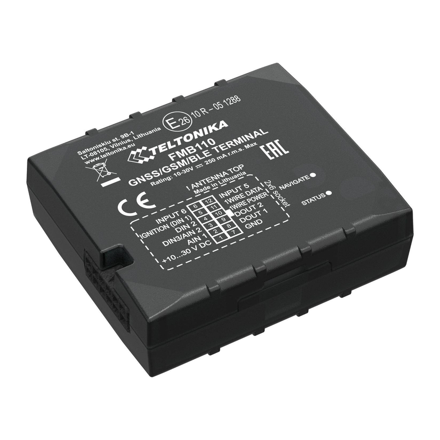
Page 3: Know Your Device
Know your device Figure 1 FMB110 device view FMB110 | Wiki... -
Page 4: Pinout
Pinout Table 1 FMB110 2x6 socket pinout Pin number Pin name Description VCC (10-30)V DC (+) Power supply (+10-30 V DC). Analog input, channel 1. Input range: 0- AIN 1 30 V DC. Analog input, channel 2. Input range: 0- AIN 2 / DIN 3 30 V DC / Digital input, channel 3. -
Page 5: Wiring Scheme
Wiring scheme Figure 3 FMB110 Wiring scheme Automotive relay FMB110 | Wiki... -
Page 6: Set Up Your Device
Set up your device How to insert Micro-SIM card 1. Gently remove FMB110 cover using plastic pry tool from both sides. 2. Insert Micro-SIM card as shown with PIN request disabled or read our Wiki how to enter it later in Configurator. Make sure that Micro-SIM card cut-off corner is pointing forward to slot. -
Page 7: Pc Connection (Windows)
Setup will continue installing the driver and eventually the confirmation window will appear. Click Finish to complete the setup. 1. Power-up FMB110 with DC voltage (10 – 30 V) power supply using supplied power cable. LED’s should start blinking, see Configuration (Windows) “LED indications”. - Page 8 Various Status window tabs display information about GNSS, GSM, I/O, Maintenance and etc. FMB110 has one user editable profile, which can be loaded and saved to the device. After any modification of configuration the changes need to be saved to device using Save to device button.
-
Page 9: Mounting Recommendations
Depending on the car model, this may happen in 5 to 30 minutes period. ▬ When the module is connected, measure the voltage again to make sure it did not decrease. ▬ It is recommended to connect to the main power cable in the fuse box. FMB110 | Wiki... -
Page 10: Led Indications
Device is not working or Device is in boot mode Technology Quad-band 850 / 900 / 1800 / 1900 2G bands GPRS Multi-Slot Class 12 (up to 240 Data transfer kbps), GPRS Mobile Station Class B Data support SMS (text/data) FMB110 | Wiki... - Page 11 128MB internal flash memory LLS (Analog), LV-CAN200, ALL-CAN300, Fuel monitoring ODBII dongle Physical specification Digital Input 1, Accelerometer, External Dimensions 79 x 43 x 12 mm (L x W x H) Ignition detection Power Voltage, Engine RPM Weight 50 g FMB110 | Wiki...
-
Page 12: Electrical Characteristics
Additional error on 30 V, Range 2 Conditions) voltage Output Supply Voltage 1-Wire Input Voltage threshold (DIN1) Supply voltage +4.5 +4.7 Input Voltage threshold (DIN2) Output inner resistance Ω Output current (U > 3.0 V) Short circuit current (U = 0) FMB110 | Wiki... -
Page 13: Safety Information
Installation and/or handling during a lightning operator. All related devices must meet the requirements of EN storm is prohibited. 60950-1 standard. The device FMB110 is not designed as a navigational device for The device is susceptible to water and humidity. boats. FMB110 | Wiki... -
Page 14: Certification And Approvals
Certification and Approvals FMB110 EAC • • FMB110 REACH FMB110 Declaration of IMEI assignment • This sign on the package means that it is necessary to read the User‘s Manual before your start using the device. Full User‘s Manual version can be found in our Wiki.
Need help?
Do you have a question about the FMB110 and is the answer not in the manual?
Questions and answers