Teltonika FMB125 Quick Manual
Dual-sim tracker with rsr232, rs485 interfaces
Hide thumbs
Also See for FMB125:
- Quick manual (16 pages) ,
- Getting started (12 pages) ,
- First start-up quick start manual (9 pages)
Table of Contents
Advertisement
Quick Links
Advertisement
Table of Contents

Related Manuals for Teltonika FMB125


Summary of Contents for Teltonika FMB125
- Page 1 FMB125 Dual-SIM tracker with RSR232, RS485 interfaces Quick Manual v1.7...
-
Page 2: Table Of Contents
Quick SMS configuration ....................................10 Mounting recommendations..................................12 LED indications ......................................... 13 Basic characteristics ......................................13 Electrical characteristics ....................................16 Safety information ......................................18 Certification and Approvals .................................... 19 Warranty ........................................... 21 Warranty disclaimer ......................................21 Quick Manual v1.7 // FMB125... -
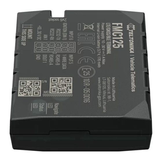
Page 3: Know Your Device
KNOW YOUR DEVICE TOP VIEW BOTTOM VIEW (WITHOUT COVER) TOP VIEW (WITHOUT COVER) MICRO-USB GNSS ANTENNA BATTERY SOCKET SOCKET SOCKET STATUS DUAL-SIM SLOT NAVIGATE Quick Manual v1.7 // FMB125... -
Page 4: Pinout
1. Open collector output. Max. 0,5 A DC RS485 – A Signal A wire for RS485 RS485 – B Signal B wire for RS485 1WIRE DATA Data for 1–Wire devices. INPUT 5 RX EXT (LVCAN - RX). Quick Manual v1.7 // FMB125... -
Page 5: Wiring Scheme
IRIDIUM EDGE ® RS232-TX RS485-B RS232-RX RS485-A BUFFERED MULTIPLE RS485 TRANSPARENT AIN1 DOUT1 FUEL GAUGE LLS SENSORS MODE +10...30 V DC GARMIN ANALOG RS232 POWER SUPPLY STARTER LLS SENSOR LLS SENSOR 10 - 30V DC BUZZER Quick Manual v1.7 // FMB125... -
Page 6: Set Up Your Device
SIM card cut-off corner Page 7, "PC Connection is pointing outward from (Windows)" slot. SIM slot 1 is closer to PCB, SIM slot 2 is the top one. wiki.teltonika-gps.com/view/ 1 FMB125_Security_info wiki.teltonika-gps.com/view/ 2 Teltonika_Configurator Quick Manual v1.7 // FMB125... -
Page 7: Pc Connection (Windows)
PC CONNECTION (WINDOWS) Power-up FMB125 with DC voltage (10 – 30 V) power supply using supplied power cable. LED’s should start blinking, see “LED indications ”. Connect device to computer using Micro-USB cable or Bluetooth connection: • Using Micro-USB cable •... -
Page 8: Configuration
CONFIGURATION At first FMB125 device will have default factory settings set. These settings should be changed according to the users needs. Main configuration can be performed via Teltonika Configurator software. Get the latest Configurator version from here . Configurator operates on Microsoft Windows OS and uses prerequisite MS .NET Framework. Make sure you have the correct version installed. - Page 9 Most important configurator section is GPRS – where all your server and GPRS setttings can be configured and Data Acquisition – where data acquiring parameters can be configured. More details about FMB125 configuration using Configurator can be found in our Wiki wiki.teltonika-gps.com/view/FMB125_Status_info wiki.teltonika-gps.com/view/FMB125_Status_info#GNSS_Info wiki.teltonika-gps.com/view/FMB125_Status_info#GSM_Info wiki.teltonika-gps.com/view/FMB125_Status_info#I.2FO_Info...
-
Page 10: Quick Sms Configuration
2003 – APN password (if there are no APN password, empty field should be left) SERVER SETTINGS: 2004 – Domain 2005 – Port 2006 – Data sending protocol (0 – TCP, 1 – UDP) Quick Manual v1.7 // FMB125... - Page 11 If device has made a stationary and record ignition is off After successful SMS configuration, FMB125 device will synchronize time and update records to configured server. Time intervals and default I/O elements can be changed by using Teltonika Configurator SMS parameters wiki.teltonika-gps.com/view/Teltonika_Configurator...
-
Page 12: Mounting Recommendations
If the wire is fixed with the bolt, the loop must be connected to the end of the wire. • For better contact scrub paint from the spot where loop is going to be connected. Quick Manual v1.7 // FMB125... -
Page 13: Led Indications
Blinking every two Sleep mode seconds Technology Blinking fast for a Quad-band 850 / 900 / 1800 / 1900 Modem activity 2G bands short time Device is not working or Device is in boot mode Quick Manual v1.7 // FMB125... - Page 14 Headset OBDII dongle peripherals Inateck Barcode Scanner, Universal Weight 55 g BLE sensors support OPERATING ENVIRONMENT wiki.teltonika-gps.com/view/FMB125_Sleep_modes 1 teltonika-gps.com/products/accessories 2 Operating temperature -40 °C to +85 °C wiki.teltonika-gps.com/view/How_to_connect_Bluetooth_Hands_Free_ 3 adapter_to_FMB_device (without battery) wiki.teltonika-gps.com/view/How_to_connect_OBD_II_Bluetooth_ 4 Dongle_to_FMB_device Quick Manual v1.7 // FMB125...
- Page 15 Towing detection, Crash detection, Auto Geofence, Manual Geofence, Trip Sleep, Online Deep Sleep, Deep Sleep modes Sleep, Ultra Deep Sleep wiki.teltonika-gps.com/view/FOTA_WEB 7 wiki.teltonika-gps.com/view/Teltonika_Configurator 8 teltonika-gps.com/products/trackers/can-obd-data/lv-can200 teltonika-gps.com/products/trackers/can-obd-data/all-can300 10 wiki.teltonika-gps.com/view/How_to_connect_OBD_II_Bluetooth_ 11 wiki.teltonika-gps.com/view/FMB125_Features_settings Dongle_to_FMB_device 5 wiki.teltonika-gps.com/view/FMB125_Sleep_modes teltonika-gps.com/products/trackers/can-obd-data/can-control 6 12 Quick Manual v1.7 // FMB125...
-
Page 16: Electrical Characteristics
Input resistance, kΩ DIGITAL INPUT Range 2 Input resistance (DIN1) kΩ Measurement error on 12 V, Range 2 Input voltage Supply (Recommended Additional error on 12 voltage Operating Conditions) V, Range 2 Input Voltage threshold (DIN1) Quick Manual v1.7 // FMB125... - Page 17 30 V, Range 2 Additional error on 30 V, Range 2 OUTPUT SUPPLY VOLTAGE 1-WIRE Supply voltage +4.5 +4.7 Output inner resistance Ω Output current (Uout > 3.0 V) Short circuit current (Uout = 0) Quick Manual v1.7 // FMB125...
-
Page 18: Safety Information
DO NOT touch the device before unplugging the power supply. This message contains information on how to operate FMB125 All wireless data transferring devices produce safely. By following these requirements and recommendations, interference that may affect other devices which are you will avoid dangerous situations. -
Page 19: Certification And Approvals
The Independent Communications Authority of South Africa (ICASA) is the official regulator of the SIRIM QAS International Sdn. Bhd. is Malaysia’s South African communications, broadcasting and leading testing,inspection and certification body. postal services sectors. Quick Manual v1.7 // FMB125... - Page 20 IMEI number. This renders the phone useless on that network and sometimes other All newest certificates may be found in our Wiki networks too, whether or not the phone's subscriber identity module (SIM) is changed. wiki.teltonika-gps.com/view/FMB125_Certification_%26_Approvals Quick Manual v1.7 // FMB125...
-
Page 21: Warranty
Warranty does not apply to any consequential damages. • Warranty is not applicable for supplementary product equipment (i. e. PSU, power cables, antennas) unless the accessory is defective on arrival. • More information on what is RMA wiki.teltonika-gps.com/view/RMA_guidelines Quick Manual v1.7 // FMB125...
Need help?
Do you have a question about the FMB125 and is the answer not in the manual?
Questions and answers