Table of Contents
Advertisement
Quick Links
https://wiki.teltonika-gps.com/view/FMB120_First_Start
FMB120 First Start
Main Page
>
Advanced Trackers
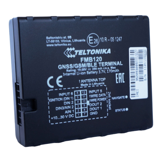
GNSS/GSM/Bluetooth tracker with internal GNSS/GSM antennas and internal battery
Contents
1 How to insert Micro-SIM card and connect the battery
How to insert Micro-SIM card and connect the battery
1.
Gently remove FMB120 cover using plastic pry tool from both sides.
Note: To properly open a new case please watch this video.
2.
Insert Micro-SIM card as shown with PIN request disabled or read
enter it later in
pointing forward to slot.
3.
Connect battery as shown to device. Position the battery in place where it does not obstruct
other components.
4.
After configuration, see
Device is ready to be installed.
Micro-SIM card insertion/removal must be performed when device is powered off –
external voltage and internal battery disconnected. Otherwise Micro-SIM card might be
damaged or device will not detect it.
>
FMB120
> FMB120 First Start
Configurator. Make sure that Micro-SIM card cut-off corner is
Teltonika
"PC Connection
(Windows)", attach device cover back.
Security info
how to
Advertisement
Table of Contents

Subscribe to Our Youtube Channel
Related Manuals for Teltonika FMB120


Summary of Contents for Teltonika FMB120
- Page 1 5.1 Precautions How to insert Micro-SIM card and connect the battery Gently remove FMB120 cover using plastic pry tool from both sides. Note: To properly open a new case please watch this video. Insert Micro-SIM card as shown with PIN request disabled or read...
- Page 2 Battery placement after complete device disassembling Using double sided tape, stick internal battery to the bottom part of the device case. Battery should be glued approximately 15 millimeters from the bottom wall of the case. Picture on the left. Connect battery to the PCB. Gently place PCB into the bottom case.
- Page 3 Setup will continue installing the driver and eventually the confirmation window will appear. Click Finish to complete the setup. Configuration (Windows) At first FMB120 device will have default factory settings set. These settings should be changed according to the user's needs. Teltonika Configurator Main configuration can be performed via software.
- Page 4 Maintenance and etc. FMB120 has one user editable profile, which can be loaded and saved to the device. After any modification of configuration the changes need to be saved to device using Save to device button. Main buttons offer following functionality: Load from device –...
- Page 5 If device has made a record it is sent to the server every 120 seconds After successful SMS configuration, FMB120 device will synchronize time and update records to configured server. Time intervals and default I/O elements can be changed by using Teltonika Configurator parameters.
- Page 6 Installation photos FMB120 is the device that has internal GNSS and GSM antenna. Device should be mounted with the sticker / engraving view to the open sky (metal free). FMB120 area with engraving is shown in figure below: FMB120 can be mounted under the plastic panel behind the front window, with the sticker / engraving direction to a window (sky).
- Page 7 Safety information This message contains information on how to operate FMB120 safely. By following these requirements and recommendations, you will avoid dangerous situations. You must read these instructions carefully and follow them strictly before operating the device! The device uses SELV limited power source. The nominal voltage is +12 V DC. The allowed voltage range is +10..+30V DC.
Need help?
Do you have a question about the FMB120 and is the answer not in the manual?
Questions and answers