Table of Contents
Advertisement
User Manual
Tentative Version
Thank you for purchasing this product.
Be sure to read this documentation before use.
This documentation includes important safety precautions and instructions on how to operate the unit. Be sure to read this documentation to ensure
proper operation.
The contents of this documentation are subject to change without notice for the purpose of improvement.
@2022 JAI
SW-4010Q-MCL-M52
RGB Color & SWIR Prism Line Scan Camera
with Mini Camera Link Interface
SW-4010Q-MCL-M52_Manual_Ver.Tentative_2022-11-25
Document Version: Tentative
Advertisement
Table of Contents

Related Manuals for JAI SW-4010Q-MCL-M52


Summary of Contents for JAI SW-4010Q-MCL-M52
- Page 1 User Manual Tentative Version SW-4010Q-MCL-M52 RGB Color & SWIR Prism Line Scan Camera with Mini Camera Link Interface Document Version: Tentative SW-4010Q-MCL-M52_Manual_Ver.Tentative_2022-11-25 Thank you for purchasing this product. Be sure to read this documentation before use. This documentation includes important safety precautions and instructions on how to operate the unit. Be sure to read this documentation to ensure proper operation.
-
Page 2: Table Of Contents
SW-4010Q-MCL-M52 User Manual (Tentative) Table of Contents Table of Contents Table of Contents About Technical Note Notice/Warranty Notice Warranty Certifications CE Compliance Warning Usage Precautions Notes on Cable Configurations Notes on Attaching the Lens Notes on Camera Link Cable Connections... - Page 3 SW-4010Q-MCL-M52 User Manual (Tentative) Table of Contents ③ Camera Link Cable ④ Frame Grabber Board ⑤ AUX Cable (10 Pin) (Option) ⑥ DC IN / Trigger IN Connection Cable ⑦ AC Adapter (Power Supply) Step 2: Verify Camera Operation Step 3: Verify the Connection Between the Camera and PC...
- Page 4 SW-4010Q-MCL-M52 User Manual (Tentative) Table of Contents Pixel Sensitivity Correction Defective Pixel Correction Gain Control (RGB Channels) Gain Control (SWIR Channel) Gamma Function To Use the Gamma Function LUT (Lookup Table) To Use the LUT Function LUT Value Shading Correction...
- Page 5 SW-4010Q-MCL-M52 User Manual (Tentative) Table of Contents DigitalIOControl CounterAndTimerControl EncoderControl UserSetControl TransportLayerControl PulseGenerator ShadingControl CorrectionControl SWIRImageFormatControl SWIRAcquisitionControl SWIRAnalogControl SWIRLUTControl SWIRTransportLayerControl SWIRShadingControl SWIRCorrectionControl SWIRBlemishControl Miscellaneous Troubleshooting Power Supply and Connections Image Display Settings and Operations Specifications Spectral Response Dimensions (SW-4010Q-MCL-M52) Lens Dimensions (JMO-M5231-2828-C4)
-
Page 6: About Technical Note
Table of Contents About Technical Note Some additional technical information is provided on the JAI website as Technical Notes. In this manual, if a technical note is available for a particular topic, the above icon is shown. Please refer to the following URL for Technical notes. -
Page 7: Notice/Warranty
The material contained in this manual consists of information that is proprietary to JAI Ltd., Japan, and may only be used by the purchasers of the product. JAI Ltd., Japan makes no warranty for the use of its product and assumes no responsibility for any errors which may appear or for damages resulting from the use of the information contained herein. -
Page 8: Warning
SW-4010Q-MCL-M52 User Manual (Tentative) Notice/Warranty Warning Changes or modifications to this unit not expressly approved by the party responsible for FCC compliance could void the user’s authority to operate the equipment. - 8 -... -
Page 9: Usage Precautions
SW-4010Q-MCL-M52 User Manual (Tentative) Usage Precautions Usage Precautions Notes on Cable Configurations The presence of lighting equipment and television receivers nearby may result in video noise. In such cases, change the cable configurations or placement. Notes on Attaching the Lens... -
Page 10: Phenomena Specific To Cmos Image Sensors
SW-4010Q-MCL-M52 User Manual (Tentative) Usage Precautions Phenomena Specific to CMOS Image Sensors The following phenomena are known to occur on cameras equipped with CMOS image sensors. These do not indicate malfunctions. Aliasing: When shooting straight lines, stripes, and similar patterns, vertical aliasing (zigzag distortion) may appear on the monitor. -
Page 11: Package Contents
SW-4010Q-MCL-M52 User Manual (Tentative) Package Contents Package Contents Camera (1) Sensor protection cap (1) Dear customer (sheet) (1) Optional Accessories (Sold Separately) Custom Lens: JMO-M5231-2828-C4 - 11 -... -
Page 12: Features
Features Features The SW-4010Q-MCL-M52 is a line scan camera with three CMOS sensors and one InGaAs linear image sensor for the R, G, B, and SWIR channels, mounted on a prism. The camera has a Camera Link pixel clock of 42.5/65/85 MHz and is capable of scanning up to 40 kHz (RGB) / 39kHz (SWIR). -
Page 13: Parts Identification
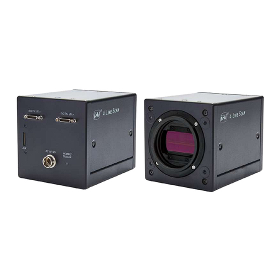
SW-4010Q-MCL-M52 User Manual (Tentative) Parts Identification Parts Identification ① Lens Mount (M52-Mount) ② Digital I/O-1 and Digital I/O-2 Video Output Connectors ③ POWER/TRIG LED ④ DC IN/TRIG Connector (12-Pin Round) ⑤ AUX Connector (10-pin) ⑥ ⑦ Mounting Holes ① Lens Mount (M52-Mount) Mount the custom lens (JMO-M5231-2828-C4, sold separately) to the camera. - Page 14 SW-4010Q-MCL-M52 User Manual (Tentative) Parts Identification Camera Link Connector 1 Input Signal Description Output 1, 26 Shield 2 (-), 15 (+) TxOUT0 Data output 3 (-), 16 (+) TxOUT1 Data output DIGITAL I/O - 1 4 (-), 17 (+) TxOUT2...
-
Page 15: ③ Power/Trig Led
SW-4010Q-MCL-M52 User Manual (Tentative) Parts Identification ③ POWER/TRIG LED Indicates the power or trigger input status. Status Lit amber Camera initializing. Lit green Camera in operation During operation in trigger mode, trigger signals are being input. Blinking Note: The blinking interval is not related to the actual input interval of the green external trigger. - Page 16 SW-4010Q-MCL-M52 User Manual (Tentative) Parts Identification TTL Signal specification Output voltage: Low 0.0V, High 5.0V TTL out signal specification (Typ.) Input/Output current: +/-32mA TTL in signal specification (Typ.) Input voltage: Low 0.0 ~ 0.8V, High 2.0 ~ 5.5V Caution: About Opto In: Check the recommended external input circuit diagram (reference example) and connect correctly.
-
Page 17: ⑤ Aux Connector (10-Pin)
SW-4010Q-MCL-M52 User Manual (Tentative) Parts Identification ⑤ AUX Connector (10-pin) Connect the cable for DC IN / trigger IN here. Camera side: Equivalent to Hirose Electronic 3260-10S3(55) Cable side: Equivalent to Hirose Electronic 3240-10P-C(50) Pin No. Attribute Name Description TTL OUT2... -
Page 18: Preparation
Save the current setting configurations in user memory. Short ASCII Commands The most universal method for controlling a Camera Link camera such as SW-4010Q-MCL-M52 is by the use of short ASCII commands sent via serial communications. All Camera Link frame grabber boards support the use of these short ASCII commands. -
Page 19: Step 1: Connect Devices
(Setting List). The SW-4010Q-MCL-M52 fully supports applications written using GenICam-based SDKs. The advantage of this is that programs written using GenICam names can be applied with little or no modification to control cameras with other GenICam-compliant interfaces and even GenICam- compliant cameras from different vendors. -
Page 20: ① Lens
SW-4010Q-MCL-M52 User Manual (Tentative) Preparation ① Lens Attach the customized lens JMO-M5231-2828-C4 (sold separately) to the camera. This lens is for a prism camera and is optimized to match the camera's pixel size. Focal length: 28mm Spectral Range: 400 - 1700 nm Aperture: F2.8 - F22... -
Page 21: ② Mounting
SW-4010Q-MCL-M52 User Manual (Tentative) Preparation ② Mounting When mounting the camera directly to a wall or other device, use screws that match the mounting holes on the camera (M4: depth 6mm). Caution: For heavy lenses, be sure to support the lens itself. Do not use configurations in which its weight is supported by the camera. -
Page 22: Step 2: Verify Camera Operation
SW-4010Q-MCL-M52 User Manual (Tentative) Preparation Step 2: Verify Camera Operation When power is supplied to the camera while the necessary equipment is connected, the POWER/TRIG LED at the rear of the camera lights amber, and initialization of the camera starts. -
Page 23: Step 3: Verify The Connection Between The Camera And Pc
Start Bit: 1bit Stop Bit: 1 bit Parity: None Xon/Xoff Control: None 2. Enter the command DVN? <CR><LF> from the terminal emulator software. If correctly connected, response DVN = JAI Corporation will be displayed. Item Short ASCII Command Description DVN? <CR><LF>... -
Page 24: Step 4: Configure Basic Settings For The Camera
SW-4010Q-MCL-M52 User Manual (Tentative) Preparation Step 4: Configure Basic Settings for the Camera Note: On this camera, you must configure both the RGB and SWIR channels individually. Configure the Camera Output Formats Configure the pixel formats of the image output from the RGB and SWIR channels. -
Page 25: Configure The Imagescalingmode Settings
SW-4010Q-MCL-M52 User Manual (Tentative) Preparation Configure the ImageScalingMode Settings Notes: The SWIR channel does not support the ImageScalingMode function. For more information on this function, see Image Scaling Mode (Xscale). 1. To check the ImageScalingMode setting, enter the command ISM?<CR><LF> from the terminal emulator software. -
Page 26: Configure Trigger, Exposure, And Line Rate Settings
SW-4010Q-MCL-M52 User Manual (Tentative) Preparation Configure Trigger, Exposure, and Line Rate Settings This section describes how to control the exposure time with or without external triggers. Note: For the detailed setting information, see Short ASCII Commands for Trigger, Exposure, Line Rate Settings. -
Page 27: Short Ascii Commands For Trigger, Exposure, Line Rate Settings
SW-4010Q-MCL-M52 User Manual (Tentative) Preparation Short ASCII Commands for Trigger, Exposure, Line Rate Settings This section shows the short ASCII commands to configure the Trigger, Exposure, and Line Rate settings. Short ASCII Item Values Command Examples Command 0: Off TR=[Param.]<CR><LF>... - Page 28 SW-4010Q-MCL-M52 User Manual (Tentative) Preparation SWIR Short ASCII Item Values Command Examples Command 0: Off IRTR=[Param.]<CR><LF> SWIRExposureMode IRTR 1: Timed (Default) IRTR?<CR><LF> 136 (Default) ~ 13306 (Unit: IRPE=[Param.]<CR><LF> SWIRExposureTime IRPE 149.9ns) IRPE?<CR><LF> 0: Off (Default) IRTG=[Param.]<CR><LF> SWIRTriggerMode IRTG 1: On IRTG?<CR><LF>M...
-
Page 29: Step 5: Adjust The Image Quality
SW-4010Q-MCL-M52 User Manual (Tentative) Preparation Step 5: Adjust the Image Quality Related Setting Items: AnalogControl To maximize the performance of the camera, configure its basic function in the following order. Note: On this camera, you must configure both the RGB and SWIR channels individually. - Page 30 SW-4010Q-MCL-M52 User Manual (Tentative) Preparation For more information, see the following Short ASCII command table. Short ASCII Item Values Command Examples Command 0:Off PBC=[Param.]<CR><LF> 1:Default (Default) PBC?<CR><LF> PixelBlack 2:User1 CorrectionMode 3:User2 Note: Default stores correction data with factory settings. 4:User3 PerformPixelBlackCalibration PBR PBR<CR><LF>...
-
Page 31: Prnu Correction (Pixel Gain Correct)
SW-4010Q-MCL-M52 User Manual (Tentative) Preparation PRNU Correction (Pixel Gain Correct) PRNU (photo response non-uniformity) is a variation between pixels generated by the sensor under bright conditions. If the line rate is slowed or a long exposure time is set, the dark current in the sensor may change and the state of the PRNU may change. - Page 32 SW-4010Q-MCL-M52 User Manual (Tentative) Preparation SWIR 1. Select User to save the gain correction value with SWIRPixelGainCorrect. Note: You cannot perform calibration when Off or Factory is selected. 2. Gain correction data is automatically generated by SWIRPixelGainCalibration and saved in the user area specified in step 1.
-
Page 33: Adjust The Black Level
SW-4010Q-MCL-M52 User Manual (Tentative) Preparation Adjust the Black Level Black level correction is a function for adjusting the setup level. 1. Configure the RGB channels' black level with BlackLevel. 2. Configure the SWIR channel's black level with SWIRBlackLevel. For more information, see the following Short ASCII command table. -
Page 34: Adjust The White Balance
7:Preset 7500K Step 6: Configure Various Other Settings “Setting List” or "SW-4010Q-MCL-M52 Command List" (available from the JAI website) to configure settings as necessary. Note: We recommend performing DSNU and PRNU calibration again whenever the line rate setting is changed significantly. -
Page 35: Step 7: Save The Settings
SW-4010Q-MCL-M52 User Manual (Tentative) Preparation Step 7: Save the Settings Related Setting Items: UserSetControl The configured setting values will be deleted when the camera is turned off. By saving current setting values to user memory, you can load and recall them whenever necessary. You can save up to three sets of user settings in the camera. -
Page 36: Load The User Settings
SW-4010Q-MCL-M52 User Manual (Tentative) Preparation Load the User Settings 1. Stop image acquisition. User settings can only be loaded when image capture on the camera is stopped. 2. Specify the storage location (UserSet1 - UserSet3) using the UserSetLoad command and read the settings of the camera. -
Page 37: Main Functions
SW-4010Q-MCL-M52 User Manual (Tentative) Main Functions Main Functions This chapter describes the camera's main functions. Basic Function Matrix Related Setting Items: DigitalIOControl, AcquisitionControl, SWIRAcquisitionControl, PulseGenerator The following signals can be used as sources for each output destination (TriggerSelector, LineSelector, PulseGeneratorSelector). - Page 38 SW-4010Q-MCL-M52 User Manual (Tentative) Main Functions Output Destination Trigger LineSelector PulseGeneratorSelector Pulse Pulse Pulse Pulse Source Signal (Cross Line Line 1 Line 8 Line9 Line12 NAND0 NAND1 Genera- Genera- Genera- Genera- Point Switch Point) Start TTLOut1 TTLOut2 TTLOut3 TTLOut4 tor 0...
-
Page 39: Gpio (Digital Input/Output Settings)
SW-4010Q-MCL-M52 User Manual (Tentative) Main Functions GPIO (Digital Input/Output Settings) Related Setting Items: DigitalIOControl The camera can input/output the following signals to and from external input/output connectors. TTL OUT 1 (Line 1) DC IN / TRIG IN Connector (12-pin) TTL OUT 4 (Line 12) -
Page 40: Camera Output Formats
SW-4010Q-MCL-M52 User Manual (Tentative) Main Functions For digital output, set the output source signal using LineSource. Set the source signal in the same way for NAND Logic (Nand0In1, Nand0In2, Nand1In1, Nand1In2). Note: For more information on the combinations of source signals and output destinations, Basic Function Matrix. - Page 41 SW-4010Q-MCL-M52 User Manual (Tentative) Main Functions SWIR - 41 -...
-
Page 42: Camera Link Bit Assignments
SW-4010Q-MCL-M52 User Manual (Tentative) Main Functions Camera Link Bit Assignments This camera conforms to the Camera Link standard. The bit assignments are as follows. Camera Link Connector 1 (RGB) RGB10BasePacked Port/Signal 8-bit (RGB8) Connector Pin Name RGB12BasePacked Port A0 R_D0... - Page 43 SW-4010Q-MCL-M52 User Manual (Tentative) Main Functions Camera Link Connector 2 (SWIR) Port/Signal Mono8 Mono10/Mono12 Connector Pin Name Port A0 SWIR_D0 SWIR_D0 Port A1 SWIR_D1 SWIR_D1 Port A2 SWIR_D2 SWIR_D2 Port A3 SWIR_D3 SWIR_D3 Port A4 SWIR_D4 SWIR_D4 Port A5 SWIR_D5...
-
Page 44: Image Scaling Mode (Xscale)
Image Scaling Mode (Xscale) Related Setting Items: ImageFormatControl JAI's Xscale algorithm digitally reduces the sensor's pixel resolution by specifying the RGB channels' scaling. This function allows finer adjustment of resolution than the conventional Binning function. The output image types are Average or Sum. -
Page 45: Swirpixelmode And Swirhalfpixelmode
SW-4010Q-MCL-M52 User Manual (Tentative) Main Functions 4. When ImageScalingMode is set to On, specify the scaling using ImageScalingHorizontalRaw. For example, if you want to reduce the output image by 50%, set ImageScalingHorizontalRaw to 2048. Note: ImageScalingHorizontalRaw cannot be configured when ImageScalingMode is set to SWIRPixelMode or SWIRHalfPixelMode. -
Page 46: Exposure Mode
SW-4010Q-MCL-M52 User Manual (Tentative) Main Functions Notes: The ImageScalingHorizontal values are calculated from the following formulas and they are not 0.3 or 0.6 exact. If you use a Control Tool, the following value will be displayed. SWIRPixelMode : ImageScalingHorizontal = ImageScalingHorizontalRaw/ImageScalingBaseAbs = 1228/4096 ≒... -
Page 47: Trigger Control
SW-4010Q-MCL-M52 User Manual (Tentative) Main Functions Trigger Control Related Setting Items: AcquisitionControl, SWIRAcquisitionControl The camera allows Line Start trigger controls to be performed via external trigger signals. The Line Start trigger allows exposure control via the trigger signal inputs. Note: The settings for exposure control and triggers are related to each other. Be sure to... -
Page 48: Pixel Sensitivity Correction
SW-4010Q-MCL-M52 User Manual (Tentative) Main Functions Pixel Sensitivity Correction Related Topic: CorrectionControl, SWIRCorrectionControl Correct variations between the sensor’s pixels. Calibration must be performed within the camera and correction data must be created beforehand. DSNU (PixelBlackCorrect) / PRNU (PixelGainCorrect) can be reduced using that correction data. -
Page 49: Defective Pixel Correction
SW-4010Q-MCL-M52 User Manual (Tentative) Main Functions Defective Pixel Correction Related Setting Items: SWIRBlemishControl Correct defective pixels. Correction is performed using the average value between the pixels to the immediate left and right. Up to eight defective pixels can be corrected. The pixels at the left and right edges cannot be corrected. -
Page 50: Gain Control (Rgb Channels)
SW-4010Q-MCL-M52 User Manual (Tentative) Main Functions Gain Control (RGB Channels) Related Setting Items: AnalogControl The following gain functions are available on the camera: Analog Base Gain and Digital Gain (MasterMode, IndividualMode) Analog Base Gain Analog base gain (ABG) is gain that is performed to the analog video signal output from the sensor. -
Page 51: Gain Control (Swir Channel)
SW-4010Q-MCL-M52 User Manual (Tentative) Main Functions Gain Control (SWIR Channel) Related Setting Items: SWIRAnalogControl The following three gain functions are available on the camera: Sensor Conversion Gain, Analog Base Gain, and Analog Fine Gain. Sensor Conversion Gain Sensor conversion gain (SCG) is InGaAs sensors' internal gain. Settings configured individually from an external source, and the amount of gain can be adjusted via different combinations of 3- bit setting values. -
Page 52: Gamma Function
SW-4010Q-MCL-M52 User Manual (Tentative) Main Functions Analog Fine Gain Analog fine gain (AFG) is gain that is performed after the video signal passes through the CDS circuit and prior to ADC (analog digital conversion). The setting range is 0 ~ +11dB (0 ~ 308). -
Page 53: To Use The Gamma Function
SW-4010Q-MCL-M52 User Manual (Tentative) Main Functions To Use the Gamma Function Configure the settings as follows. Item Setting Value / Selectable Range Description Gamma 0.45, 0.5, 0.55, 0.6, 0.65, 0.75, 0.8, 0.9, 1.0 Select the Gamma correction value. LUTMode Gamma Use Gamma. -
Page 54: Lut (Lookup Table)
SW-4010Q-MCL-M52 User Manual (Tentative) Main Functions LUT (Lookup Table) Related Setting Items: LUTControl The LUT function is used to generate a non-linear mapping between signal values captured on the sensor and those that are output from the camera. On this camera, you can specify the output curve using 257 setting points (indexes) for the RGB channels and 256 setting points (indexes) -
Page 55: Lut Value
SW-4010Q-MCL-M52 User Manual (Tentative) Main Functions LUT Value LUT values range from 0 at the lowest to 4095 at the highest. Linear interpolation is used to calculate LUT values between the index points. - 55 -... -
Page 56: Shading Correction
SW-4010Q-MCL-M52 User Manual (Tentative) Main Functions Shading Correction Related Setting Items: ShadingControl, SWIRShadingControl The ShadingCorrection function corrects non-uniformity (i.e., shading) in the amount of light generated by the lens and lighting equipment. The following shading correction modes are available on the camera. -
Page 57: To Use The Shading Correction Function
SW-4010Q-MCL-M52 User Manual (Tentative) Main Functions To Use the Shading Correction Function The function is turned ON/OFF via serial communication. This function is not dependent on the operation mode but is effective when used during actual use. Note: You can save the setting, and have it applied whenever the power is subsequently turned on. -
Page 58: Variable Line Rate
SW-4010Q-MCL-M52 User Manual (Tentative) Main Functions Variable Line Rate Related Setting Items: AcquisitionControl, SWIRAcquisitionControl You can set the line rate to 1L or more. This function can be used to match the scanning speed of the camera to the feeding speed of the object or to lengthen the accumulation time to increase sensitivity. -
Page 59: Electronic Shutter
SW-4010Q-MCL-M52 User Manual (Tentative) Main Functions Electronic Shutter Related Setting Items: AcquisitionControl, SWIRAcquisitionControl How to Compensate Lateral Chromatic Aberration When you use this function, you can set the exposure to a preconfigured accumulation time, regardless of the line rate. SWIR Variable Range 3 μs ~ 15149.07 μs... -
Page 60: Exposureactive Function
SW-4010Q-MCL-M52 User Manual (Tentative) Main Functions ExposureActive Function Related Setting Items: AcquisitionControl, SWIRAcquisitionControl Perform external output for the timing at which video is accumulated to the sensor. The signal is output to the DC IN / TRIG IN connector (12-pin round) and the DIGITAL I/O-1 video output connector (Camera Link). -
Page 61: Color Space Conversion (Color Transformation Control)
SW-4010Q-MCL-M52 User Manual (Tentative) Main Functions Color Space Conversion (Color Transformation Control) Related Setting Items: ColorTransformationControl This camera allows you to convert the standard color space (RGB) that is used to produce colors into other color spaces, including XYZ and HSI. Five color spaces are available: RGB(sRGB), RGB(AdobeRGB), RGB(UserCustom), XYZ, and HSI. - Page 62 SW-4010Q-MCL-M52 User Manual (Tentative) Main Functions Notes: About Color Space HSI Hue Value: 0° to 360° can be specified as follows. 8bit output: Can be specified in 2° increments - 0°(00000000) ~ 360°(10110100) 10bit output: Can be specified in 0.5°increments- 0°(0000000000) ~ 360°(1011010000) 12bit output: Can be specified in 0.5°increments- 0°(000000000000) ~ 360°...
-
Page 63: Counter And Timer Control Function
SW-4010Q-MCL-M52 User Manual (Tentative) Main Functions Counter and Timer Control Function Related Setting Items: CounterAndTimerControl Note: This camera supports only the counter function. The counter function counts up change points in the camera’s internal signals using the camera’s internal counter and reads that information from the host side. This function is useful for verifying error conditions via the count value using internal camera operations. -
Page 64: Counter Occurrence Diagram
SW-4010Q-MCL-M52 User Manual (Tentative) Main Functions Counter Occurrence Diagram Note: You can reset a specific counter's count value by executing CounterReset[Counter0, Counter1, Counter2, Counter3]. Internal Camera Blocks - 64 -... -
Page 65: To Use The Counter Function
SW-4010Q-MCL-M52 User Manual (Tentative) Main Functions To Use the Counter Function Configure the settings as follows. Eight counters are available. Specify a counter (Counter0 to Counter7), and configure the settings. Setting Value Item Description Selectable Range Counter 0 ~ 7 Counter 0 ~ 7 Select the counter. -
Page 66: Chromatic Aberration Correction
SW-4010Q-MCL-M52 User Manual (Tentative) Main Functions Chromatic Aberration Correction Related Setting Items: CorrectionControl This Function corrects for the chromatic aberration of magnification caused by the lens (i.e., when the size of the image differs at the focal point for each color (RGB)). You can save correction data for three types of lenses. -
Page 67: Connecting Rotary Encoders
SW-4010Q-MCL-M52 User Manual (Tentative) Main Functions Connecting Rotary Encoders Related Setting Items: EncoderControl This camera can generate trigger signals or detect the scanning direction of the subject in response to signals output from the rotary encoder. Adjustment Procedure 1. Input the two signals (phase A and phase B) from the rotary encoder. Select which I/O on... -
Page 68: Noise Reduction Filter Functions
Center pixel read value x Center pixel coefficient + Right pixel read value x Right pixel coefficient. Noise Reduction: Apply the noise filter using JAI's own algorithm. Set the noise reduction intensity in 4 levels. Level1 = weak, Level4 = strong. -
Page 69: Setting List
Expert: For users with deep knowledge of camera functions. Guru: For advanced users who make settings, including advanced features that can cause the camera to malfunction if not set correctly. Note: For details on the ASCII Command List, see "SW-4010Q-MCL-M52 Command List" available on the JAI website. Selector A Selector is used to index which instance of the feature is accessed in situations where multiple instances of a feature exist. -
Page 70: Feature Properties
SW-4010Q-MCL-M52 User Manual (Tentative) Setting List Feature Properties Note: Depending on the setting item, you may need to change visibility. Please switch visibility (Beginner / Expert / Guru) as necessary. DeviceControl Display/configure information related to the device. Setting DeviceControl Item... - Page 71 SW-4010Q-MCL-M52 User Manual (Tentative) Setting List Setting DeviceControl Item Default Value Description Range 0: Main board Select the area of the camera's interior where the temperature DeviceTemperatureSelector is to be measured. SWIR Sensor Display the internal temperature (°C) of the device specified by...
-
Page 72: Imageformatcontrol
SW-4010Q-MCL-M52 User Manual (Tentative) Setting List ImageFormatControl Configure image format settings for the RGB channels. Setting Default Image Format Control Item Description Range Value Display the maximum image width. Default: 4096 ImageScalingMode = Off : WidthMax 4096 - BinningHorizontal=1: 4096, BinningHorizontal=2: 2048... - Page 73 SW-4010Q-MCL-M52 User Manual (Tentative) Setting List Setting Default Image Format Control Item Description Range Value Specify the horizontal scaling ratio in decimal units. For example, if you want to scale the image by 50% in the horizontal direction, ImageScalingHorizontal 0.0625 ~ 1 specify "0.5".
-
Page 74: Acquisitioncontrol
SW-4010Q-MCL-M52 User Manual (Tentative) Setting List AcquisitionControl Configure image capture settings for the RGB channels. Acquisition Control Item Setting Range Default Value Description Set the AcquisitionLineRate(Hz). AcquisitionLineRate (Hz) Min: 500 Max: Related Topic: - Width = 4096: (RGB8) 20.5kHz, (RGB10/12) 13.7kHz Variable Line Rate - Width = 2048: (RGB8) 40.8kHz, (RGB10/12) 27.3kHz... - Page 75 SW-4010Q-MCL-M52 User Manual (Tentative) Setting List Acquisition Control Item Setting Range Default Value Description Specify the sensor for which to set the ExposureTime. Select Common if ExposureTimeMode is set to Common. Select 0: Common Red/Green/Blue if ExposureTimeMode is set to Individual.
-
Page 76: Analogcontrol
SW-4010Q-MCL-M52 User Manual (Tentative) Setting List AnalogControl Configure the analog control settings for the RGB channels. Default Analog Control Item Setting Range Description Value IndividualGainMode 0:Off In IndividualGainMode, RGB can be configured individually for the entire Related Topic: 0:Off gain adjustment range of the sensor. - Page 77 SW-4010Q-MCL-M52 User Manual (Tentative) Setting List Default Analog Control Item Setting Range Description Value BlackLevelSelector 0: All Related Topic: 1: Red 0: All Select the black level to configure. Adjust the Black 2: Blue Level Set the black level value.
-
Page 78: Lutcontrol
SW-4010Q-MCL-M52 User Manual (Tentative) Setting List Default Analog Control Item Setting Range Description Value When BalanceWhiteAuto is set to ExposureOnce, display the status. 1:Succeeded AWBExposureOnce 2:Error1- G image was too bright 5:Idle Status 3:Error2 - G image was too dark... -
Page 79: Colortransformationcontrol
SW-4010Q-MCL-M52 User Manual (Tentative) Setting List ColorTransformationControl Configure color transformation settings. Related Topic: Color Space Conversion (Color Transformation Control) Color Transformation Control Setting Default Description Item Range Value 0:RGB ColorTransformationMode 1: HSI 0:RGB Set the output image format. 2: XYZ... -
Page 80: Digitaliocontrol
SW-4010Q-MCL-M52 User Manual (Tentative) Setting List DigitalIOControl Configure settings for digital input/output. Related Topic: GPIO (Digital Input/Output Settings) Setting Default Digital IO Control Item Description Range Value Select the input/output to configure. 0: Line1 TTL Out1 3: Line4 TTL In1... - Page 81 SW-4010Q-MCL-M52 User Manual (Tentative) Setting List Setting Default Digital IO Control Item Description Range Value Select the line source signal for the item selected in LineSelector. 0: Low 1: High 7: ExposureActive 9: LVAL 10: PulseGenerator0 11: PulseGenerator1 12: PulseGenerator2...
- Page 82 SW-4010Q-MCL-M52 User Manual (Tentative) Setting List Setting Default Digital IO Control Item Description Range Value Display the input/output signal status. bit0:Line1 (TTL Out1) bit1 - 2:Unused (fixed 0) bit3:Line4 (TTL In1) bit4:Line5 (Opt In1) bit5 - 6:Unused (fixed 0) bit0:Line1...
-
Page 83: Counterandtimercontrol
SW-4010Q-MCL-M52 User Manual (Tentative) Setting List CounterAndTimerControl Configure counter settings. Note: This camera only supports the counter functions. Related Topic: Counter and Timer Control Function CounterAndTimer Setting Default Description Control Item Range Value Select the counter. CounterSelector 0: Counter0 0 - 7: Counter0 - 7 Assign the Counter Event signal for which you want to read the count value to a dedicated counter and read the value. -
Page 84: Encodercontrol
SW-4010Q-MCL-M52 User Manual (Tentative) Setting List CounterAndTimer Setting Default Description Control Item Range Value Display the counter status. 0: CounterIdle CounterStatus CounterIdle 2: CounterActive 4: CounterOverflow - Count value exceedded the maximum value. EncoderControl Configure the rotary encoder related settings. -
Page 85: Usersetcontrol
SW-4010Q-MCL-M52 User Manual (Tentative) Setting List Setting Default Encoder Control Item Description Range Value Enables external setting of the upper limit of the internal frequency calculation result so that the period of the output frequency is no longer than the user-specified period. -
Page 86: Transportlayercontrol
SW-4010Q-MCL-M52 User Manual (Tentative) Setting List TransportLayerControl Display information on transport layer control for the RGB channels. Setting Default Transport Layer Control Item Description Range Value Set the transfer method (tap configuration) of images transferred from the camera at one time. -
Page 87: Pulsegenerator
SW-4010Q-MCL-M52 User Manual (Tentative) Setting List PulseGenerator Configure pulse generator settings. Pulse Generator Item Setting Range Default Value Description Set the division value for the prescaler (12 bit) using ClockPreScaler 1 ~ 4096 PixelClock as the base clock. Set the clock used for the pulse generator. This value... - Page 88 SW-4010Q-MCL-M52 User Manual (Tentative) Setting List Pulse Generator Item Setting Range Default Value Description Set the start point of the Low interval in milliseconds. When the counter reaches this value, the output will be 0. The setting range varies depending on the PulseGeneratorEndPointMs 0.15...
-
Page 89: Shadingcontrol
SW-4010Q-MCL-M52 User Manual (Tentative) Setting List ShadingControl Configure shading correction settings for the RGB channels. Related Topic: Shading Correction Default Shading Control Item Setting Range Description Value Select the shading correction method. 0: Flat ShadingCorrectionMode 0: Flat Shading Shading 1: Color Shading 0: Off Set the area to which to save shading correction data. -
Page 90: Correctioncontrol
SW-4010Q-MCL-M52 User Manual (Tentative) Setting List CorrectionControl Configure settings related to the correction function for nonuniformity in black levels and gain between pixels (RGB channels -PRNU/DSNU). Setting Default Correction Control Item Description Range Value 0: Off PixelBlackCorrectionMode (DSNU) Select the user area to which to save the black 1: Default level correction value. - Page 91 SW-4010Q-MCL-M52 User Manual (Tentative) Setting List Setting Default Correction Control Item Description Range Value ChromaticAberration 0: Off CorrectionMode 1:Lens1 Correct the color aberration that occurs at the left and 0: Off right edges due to lens characteristics. 2:Lens2 Related Topic:...
-
Page 92: Swirimageformatcontrol
SW-4010Q-MCL-M52 User Manual (Tentative) Setting List SWIRImageFormatControl Configure image format settings for the SWIR channel. SWIR Image Format Control Item Setting Range Default Value Description SWIRWidth 1024 (fixed) Display the image width. SWIRPixelFormat 0: Mono8 1: Mono10 0: Mono8 Set the pixel format. - Page 93 SW-4010Q-MCL-M52 User Manual (Tentative) Setting List Default SWIR Acquisition Item Setting Range Description Value SWIRAcquisitionLineRate (Hz) 500.012 ~ 39215 Specify the line rate (Hz). 39215 Related Topic: Variable Line Rate SWIRExposureMode 0: Off 1: Timed Select the exposure mode. Related Topic:...
-
Page 94: Swiranalogcontrol
SW-4010Q-MCL-M52 User Manual (Tentative) Setting List SWIRAnalogControl Configure the analog control settings for the SWIR channel. Setting SWIR Analog Control Item Default Value Description Range SWIRSensOutCfa 0: Zero 1: One Set the sensor’s internal conversion gain. Related Topic: Gain Control... -
Page 95: Swirlutcontrol
SW-4010Q-MCL-M52 User Manual (Tentative) Setting List SWIRLUTControl Configure LUT settings for the SWIR channel. Related Topic: LUT (Lookup Table) SWIR Lut Control Item Setting Range Default Value Description SWIRLUTSelector 0: Luminance (fixed) Display the LUT channel to control. SWIRLUTIndex 0 ~ 255 Set the LUT index table number. -
Page 96: Swirshadingcontrol
SW-4010Q-MCL-M52 User Manual (Tentative) Setting List SWIRShadingControl Configure shading correction settings for the SWIR channel. Related Topic: Shading Correction Setting SWIR Shading Control Item Default Value Description Range Set the area to which to save shading correction data. When this is set to Off, SWIRShadingCalibration will not 0: Off be executed. -
Page 97: Swircorrectioncontrol
SW-4010Q-MCL-M52 User Manual (Tentative) Setting List SWIRCorrectionControl Configure settings related to the correction function for nonuniformity in black levels and gain between pixels for the SWIR channel. Setting SWIR Correction Control Item Default Value Description Range SWIRPixelBlackCorrect (DSNU) Select the area to which to save the 0: Off pixel black correction value. -
Page 98: Swirblemishcontrol
SW-4010Q-MCL-M52 User Manual (Tentative) Setting List SWIRBlemishControl Configure settings for JAI white blemish correction for the SWIR channel. Related Topic: Defective Pixel Correction Setting Default SWIR Blemish Control Item Description Range Value 0: Off SWIRBlemishCorrect 0: Off Enable/disable blemish correction. -
Page 99: Miscellaneous
SW-4010Q-MCL-M52 User Manual (Tentative) Miscellaneous Miscellaneous Troubleshooting Check the following before requesting help. If the problem persists, contact your local JAI distributor. Power Supply and Connections Issue: The POWER/TRIG LED remains lit amber and does not turn green, even after power is supplied to the camera. -
Page 100: Specifications
SW-4010Q-MCL-M52 User Manual (Tentative) Miscellaneous Specifications Item SWIR 4K line scan CMOS image sensor × 3 1K line scan InGaAs linear image sensor x 1 Image Sensor Effective Pixels: 4096 pixels × 3 (R, G, B) Effective Pixels: 1024 pixels Pixel Size:7.5 μm x 7.5 μm... - Page 101 SW-4010Q-MCL-M52 User Manual (Tentative) Miscellaneous Item SWIR Variable Range: Width = 4096 Variable Range: 500 Hz ~ 39.2kHz RGB8: 500 ~ 20.5kHz Variable Unit: 149.9 ns RGB10/12: 500 ~ 13.7kHz Supported Mode: Variable Range: Width = 4096 Exposure Mode = OFF / TriggerMode = Off RGB8: 500 ~ 40.8kHz...
- Page 102 SW-4010Q-MCL-M52 User Manual (Tentative) Miscellaneous Item SWIR Input Range: DC +12 ~ +24V ± 10% Power Supply Voltage Power Consumption:9.3W (typ) W typical @ +12 V, 500mA/4.8W;TBD W (Max) (Default setting/25°C (12-pin) Environment / DC12 Vinput) Lens mount M52 Mount, Custom lens JMO-M5231-2828-C4 available (Sold Separately) Flange back 46.5 mm (in air), Tolerance 0 mm ~ - 0.05 mm...
-
Page 103: Spectral Response
SW-4010Q-MCL-M52 User Manual (Tentative) Miscellaneous Spectral Response - 103 -... -
Page 104: Dimensions (Sw-4010Q-Mcl-M52)
SW-4010Q-MCL-M52 User Manual (Tentative) Miscellaneous Dimensions (SW-4010Q-MCL-M52) Notes: Dimensional Tolerance: ± 0.3mm Unit: mm - 104 -... -
Page 105: Lens Dimensions (Jmo-M5231-2828-C4)
SW-4010Q-MCL-M52 User Manual (Tentative) Miscellaneous Lens Dimensions (JMO-M5231-2828-C4) Notes: Unit: mm - 105 -... -
Page 106: Comparison Of The Decibel Display And Multiplier Display
SW-4010Q-MCL-M52 User Manual (Tentative) Miscellaneous Comparison of the Decibel Display and Multiplier Display Decibels [dB] Multipliers [X] Remarks 0.501 0.562 0.631 0.708 0.794 0.891 1.122 1.259 1.413 1.585 1.778 1.995 2.239 2.512 2.818 3.162 3.548 3.981 4.467 5.012 5.623 6.31 7.079... -
Page 107: User's Record
SW-4010Q-MCL-M52 User Manual (Tentative) Miscellaneous Decibels [dB] Multipliers [X] Remarks 50.119 56.234 63.096 User's Record Model name: SW-4010Q-MCL-M52 Revision: …………… Serial No: …………… Firmware version: …………… For camera revision history, please contact your local JAI distributor. - 107 -... -
Page 108: Revision History
SW-4010Q-MCL-M52 User Manual (Tentative) Revision History Revision History Revision Date Changes Tentative 2022/11/25 Tentative Version. Trademarks Systems and product names described in this document are trademarks or registered trademarks of their respective owners. The ™ and ® symbols are not used in this document.
Need help?
Do you have a question about the SW-4010Q-MCL-M52 and is the answer not in the manual?
Questions and answers