Table of Contents
Advertisement
Quick Links
User Manual
GO-5000M-USB-UV
CMOS Digital Progressive Scan
Monochrome UV Camera Document
Version: 1.0
GO-5000M-USB-UV_Ver.1.0_Feb.2021
Thank you for purchasing this product.
Be sure to read this manual before use.
This manual includes important safety precautions and instructions on how to operate the unit. Be sure to read
this manual to ensure proper operation.
The contents of this manual are subject to change without notice for the purpose of improvement.
© 2021 JAI
Advertisement
Table of Contents

Related Manuals for JAI GO-5000M-USB-UV


Summary of Contents for JAI GO-5000M-USB-UV
- Page 1 This manual includes important safety precautions and instructions on how to operate the unit. Be sure to read this manual to ensure proper operation. The contents of this manual are subject to change without notice for the purpose of improvement. © 2021 JAI...
-
Page 2: Table Of Contents
GO-5000M-USB-UV Contents Notice/Warranty/Certifications Calculation of the maximum frame rate Usage Precautions Exposure Mode Features Trigger Control Parts Identifications Normal continuous operation Timed mode Preparation Trigger width mode Preparation Process RCT (Reset Continuous Trigger) mode Step 1:Installing the Software Video Send Mode... -
Page 3: Notice/Warranty/Certifications
The material contained in this manual consists of information that is proprietary to JAI Ltd., Japan and may only be used by the purchasers of the product. JAI Ltd., Japan makes no warranty for the use of its product and assumes no responsibility for any errors which may appear or for damages resulting from the use of the information contained herein. - Page 4 GO-5000M-USB-UV Supplement The following statement is related to the regulation on “Measures for the Administration of the control of Pollution by Electronic Information Products“ , known as “China RoHS“. The table shows contained Hazardous Substances in this camera. mark shows that the environment-friendly use period of contained Hazardous Substances is 15 years.
-
Page 5: Usage Precautions
GO-5000M-USB-UV Usage Precautions Notes on cable configurations The presence of lighting equipment and television receivers nearby may result in video noise. In such cases, change the cable configurations or placement. Notes on attaching the lens Avoiding dust particles When attaching the lens to the camera, stray dust and other particles may adhere to the sensor surface and rear surface of the lens. -
Page 6: Features
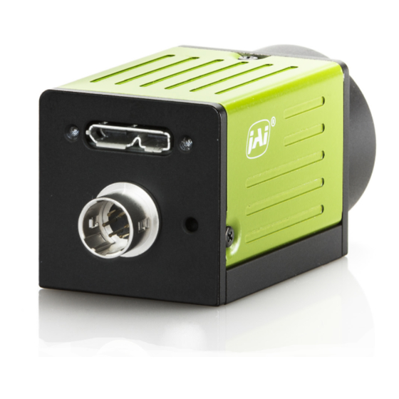
GO-5000M-USB-UV Features The GO-5000M-USB-UV is an industrial progressive scan camera equipped with a 1-inch global shutter CMOS image sensor with 5.2 effective megapixels (2560 × 2048). This CMOS image sensor has sensitivity in the UV region. The unit is compact and lightweight in design and is equipped with USB3 Vision interface. -
Page 7: Parts Identifications
GO-5000M-USB-UV Parts Identification ① Lens mount(C-mount) Mount a C-mount lens, microscope adapter, etc. here. ❖ Before mounting a lens, be sure to refer to “Step 2:Connecting Devices” and confirm the precautions for attaching a lens and the supported lens types. - Page 8 GO-5000M-USB-UV ③ POWER/TRIG LED Indicates the power and trigger input status. LED status and camera status Light Status POWER/ (Lit amber) Camera initializing. TRIG LED (Lit green) Camera in operation. (Blinking green) During operation in trigger mode, trigger signals are being input.
-
Page 9: Preparation
When using the camera for the first time, install the software for configuring and controlling the camera (eBUS SDK for JAI) on the computer. ❖ When you install eBUS SDK for JAI, eBUS SDK for JAI player will also be installed. Download the eBUS SDK for JAI from the JAI website. -
Page 10: Step 2:Connecting Devices
・To prevent vignetting and to obtain the optimal resolution, use a lens that will cover the image sensor size. Model name Image Sensor GO-5000M-USB-UV Mono 1 inch 12.8mm x 10.24mm (16.392mm diagonal) Caution ・The maximum performance of the camera may not be realized depending on the lens. - Page 11 GO-5000M-USB-UV ② Direct connection(or MP-43 tripod adapter plate) When mounting the camera directly to a wall or other device, use screws that match the camera locking screw holes on the camera (M3, depth: 3 mm). Use the supplied screws to attach the tripod adapter plate.
-
Page 12: Step 3:Verifying Camera Operation
Verifying the Connection between the Camera and PC Verify whether the camera is properly recognized via Control Tool. Connecting the Camera to Control Tool Startup eBUS Player for JAI eBUS Player for JAI eBUS Player for JAI startup screen appears. — 12 —... - Page 13 GO-5000M-USB-UV eBUS Player for JAI File Tools Help Connection Disconnect Select / Connect IP address MAC address GUID Vendor Model Name Acquisition Control Source Mode Play Stop Parameters and Controls Communication control Device control Image stream control Select the camera you want to configure.
- Page 14 GO-5000M-USB-UV Check that the settings of the selected camera are displayed. eBUS Player for JAI File Tools Help Connection Disconnect Select / Connect IP address MAC address GUID XXXXXXXXXXX Vendor JAI Corporation GO-5000M-USB-UV Model JAI_DEMO Name Acquisition Control Source Mode...
-
Page 15: Step 5:Configuring Basic Settings For The Camera
GO-5000M-USB-UV Step 5: Changing the Camera Settings This section explains how to change settings by describing the procedure for changing the output format as an example. Configuring the Output Format Configure the size, position, and pixel format of the images to be acquired. -
Page 16: Step 6:Adjusting The Image Quality
GO-5000M-USB-UV Step 6: Adjusting the Image Quality Display the camera image and adjust the image quality. Displaying the Image Display the image captured by the camera. When you push [Play] button, the camera image appears in right area. File Tools Help... - Page 17 The master gain (DigitalAll) can be set x1 (0dB) to x16 (+24dB) against the analog base gain. The resolution for gain setting is x0.01/step which is 0.05dB to 0.08dB, depending on the setting value. Adjusting the Black Level The black level can be set in the following range. GO-5000M-USB-UV: DigitalAll:-256~ +255 — 17 —...
-
Page 18: Step 7:Saving The Settings
GO-5000M-USB-UV Step 7: Saving the Settings The setting values configured in the player (eBUS SDK for JAI) will be deleted when the camera is turned off. By saving current setting values to user memory, you can load and recall them whenever necessary. You can save up to three sets of user settings in the camera. -
Page 19: Main Functions
GO-5000M-USB-UV Main Functions Digital IN/OUT interface In the GO-5000M-USB-UV, the digital IN/OUT capability in the software control tool can assign the necessary signals needed for the system. Line Selector In the Line Selector, the following input and output signals can be assigned. - Page 20 GO-5000M-USB-UV Line Format Indicates the format of the line item selected in Line Selector. (No Connect, TTL, LVDS, Opt Coupled or Internal Signal) Note: In the GO-5000M-USB-UV, TTL and LVDS interface are not equipped. — 20 —...
- Page 21 GO-5000M-USB-UV GPIO This is a general interface for input and output and controls input and output for trigger signals or valid signals and pulse generator. By using this interface, you can control an external light source, make a delayed function to input a trigger signal or make a precise exposure control with PWC trigger.
-
Page 22: Optical Interface
GO-5000M-USB-UV Optical Interface The GO-5000M-USB-UV is equipped with opto-isolated inputs and outputs, providing galvanic separation between the camera’s inputs/outputs and peripheral equipment. In addition to galvanic separation, the opto-isolated inputs and outputs can cope with a wide range of voltages; the voltage range for inputs is +3.3V to +24V DC whereas outputs will handle +5V to +24V DC. -
Page 23: Opt In Filter Selector Function
GO-5000M-USB-UV Characteristics of optical interface The relationship of the input signal to the output signal through the optical interface is as follows. Input Line Voltage Range : +3.3v~+24V Input Current : 6mA~30mA Output Load(Maximum Current) : 100mA Minimum Input Pulse Width to Turn ON : 0.5us Minimum Output Pulse Width :... -
Page 24: Pulse Generator
Pulse Generator default settings Clock Pre-scaler Clock pre-scaler (Divide Value) can set the dividing value of the frequency divider (12-bit length) and the pixel clock is used for this. In the GO-5000M-USB-UV, the pixel clock is set at 48 MHz. Pulse Generator Selector This is where you select a pulse generator. - Page 25 GO-5000M-USB-UV Pulse Generator Length Set the counter up value (number of clocks, refer to Table 11) for the pulse generator. If Repeat Count value is “0”, and if Pulse Generator Clear signal is not input, the pulse generator generates the pulse repeatedly until reaching this counter up value.
- Page 26 GO-5000M-USB-UV Pulse Generator Clear Source The following clear source can be selected as the pulse generator clear signal. Pulse Generator Inverter Clear Source Signal can have polarity inverted. — 26 —...
- Page 27 GO-5000M-USB-UV Pulse Generator Setting Parameters Note: 1. If Pulse Generator Repeat Count is set to “0”, the pulse generator works in Free Running mode. — 27 —...
-
Page 28: Sensor Layout
GO-5000M-USB-UV Sensor layout The CMOS sensors used in the GO-5000M-USB-UV have the following tap and pixel layout. Camera output format Camera output format: 1X – 1Y Sensor readout system: 1-tap readout Note: The description of camera output format is based on GenICam SFNC Ver.1.5.1. -
Page 29: Pixel Format
GO-5000M-USB-UV Pixel Format Pixel Type Pixel Size — 29 —... -
Page 30: Output Timing(Horizontal)
GO-5000M-USB-UV Output timing(Horizontal) The horizontal timing of the GO-5000M-USB-UV is described below. Although the GO-5000M- USB-UV has a horizontal binning function, its horizontal frequency does not change if it is ON. So, the frame rate is not increased. *) Vertical binnig OFF... -
Page 31: Output Timing(Vertical)
GO-5000M-USB-UV Output timing(Vertical) 61.804 2354 61.804 2354 61.804 2354 1330 61.804 2354 1330 123.37 1179 123.37 1179 — 31 —... -
Page 32: Roi(Region Of Interest) Setting
GO-5000M-USB-UV ROI (Region Of Interest) setting In the GO-5000M-USB-UV, a subset of the image can be output by setting Width, Height, Offset-X, and Offset-Y. If the height is decreased, the number of lines read out is decreased and as the result, the frame rate is increased. -
Page 33: Acquisition Control
Acquisition control Acquisition control contains the following commands. Acquisition Mode In the GO-5000M-USB-UV, the following three acquisition modes are available. Single Frame In single frame mode, executing the AcquisitionStart command causes one frame to be captured. After one frame is captured, this operation is automatically stopped. - Page 34 GO-5000M-USB-UV Multi Frame In this mode, the AcquisitionStart command captures the number of frames which are specified by AcquisitionFrameCount. ◆ Normal multi-frame operation 1) AcquisitionStart command is input 2) AcquisitionTriggerWait becomes effective 3) AcquisitionActive becomes “TRUE”(accepts capture) 4) Output N frames as specified by AcquisitionFrameCount 5) AcquisitionActive becomes “FALSE”.
- Page 35 GO-5000M-USB-UV Continuous In this mode, when the AcquisitionStart command is set, the image is continuously output at the current frame rate. This is the default setting for the GO-5000M-USB-UV. ◆ Normal continuous operation 1) AcquisitionStart command is input 2) AcquisitionTriggerWait becomes effective 3) AcquisitionActive becomes “TRUE”...
- Page 36 Allowed values range from 3846 Hz to 0.125 Hz for GO-5000M-USB-UV. However, if the value entered is less than the time required for the default frame rate of the specified format, the setting is ignored and the default frame rate is used.
-
Page 37: Calculation Of The Maximum Frame Rate
GO-5000M-USB-UV Calculation of the maximum frame rate Maximum frame rate(fps) = 1 / (Roundup ([Line Period] x [Height ] + [V Blank Value]) / 1000000) Where [Line Period] = [Trow] / 24 [Trow] = Rounddown (24000000 / ((A x (2048 / [Height... -
Page 38: Exposure Mode
GO-5000M-USB-UV Exposure Mode The exposure mode can be selected from the following three ways. For trigger operation, Exposure Mode must be set to something other than OFF and Trigger Mode of Frame Start must be ON. If Exposure Mode is set at Timed, the exposure operation can be selected as follows by setting Trigger Option. -
Page 39: Trigger Control
GO-5000M-USB-UV Exposure Auto This is a function to control the exposure automatically. It is effective only for Timed. JAI ALC Reference controls the brightness. There are two modes, OFF and Continuous. OFF: No exposure control Continuous: Exposure continues to be adjusted automatically In this mode, the following settings are available. - Page 40 GO-5000M-USB-UV Trigger Selector Selects the trigger operation. In the GO-5000M-USB-UV, the following trigger operation can be selected as the trigger. Transfer Trigger operation (for delayed readout) Each trigger has the following setting parameters and those parameters are configured on each trigger selector item.
-
Page 41: Normal Continuous Operation
GO-5000M-USB-UV Trigger Overlap In the GO-5000M-USB-UV, the trigger overlap function is fixed to Read Out. Read Out: The trigger pulse can be accepted during the sensor readout. Normal continuous operation This is used for applications which do not require triggering. -
Page 42: Trigger Width Mode
GO-5000M-USB-UV Note 1: The trigger is input through 6P optical input. Accordingly, the timing will be changed if the optical filter is set to the other figures. Note 2: Other timings are internal operating timing of the camera. Trigger width mode In this mode, the exposure time is equal to the trigger pulse width. -
Page 43: Rct (Reset Continuous Trigger) Mode
GO-5000M-USB-UV Note 1: The trigger is input through 6P optical input. Accordingly, the timing will be changed if the optical filter is set to the other figures. Note 2: Other timings are internal operating timing of the camera. RCT (Reset Continuous Trigger) mode RCT mode can use ALC control to ensure that the proper exposure is set when the trigger pulse is input. - Page 44 GO-5000M-USB-UV RCT mode timing after the trigger is input Primary settings to use this mode Exposure Mode: Timed Trigger Mode: ON Trigger Option: RCT Optical Filter Selector: 10μs If ALC control is used together with RCT mode, then Exposure auto: Continuous...
-
Page 45: Video Send Mode
GO-5000M-USB-UV Video Send Mode The GO-5000M-USB-UV has a Video Send Mode and it includes the following operations. Sequence ROI Trigger This mode allows the user to define a preset sequence of up to 10 images, each with its own ROI, exposure time and gain values. This mode has two operation modes. - Page 46 GO-5000M-USB-UV Trigger Sequence mode basic timing In this mode, as each trigger input is received, the image data associated with the next index within the preset sequence is output. In the trigger sequence mode, it is not possible to input the trigger while the current index is executing.
- Page 47 GO-5000M-USB-UV Sequence index table (Default) The following table shows the default settings. Descriptions of index table parameters Note 1: If the binning mode is used, the maximum value is changed. — 47 —...
-
Page 48: Multi Roi Mode
GO-5000M-USB-UV Multi ROI mode In the GO-5000M-USB-UV, the width and height of 5 separate ROIs within the full image area can be set as required. Each image can be overlapped. The location of each ROI can also be set as required. -
Page 49: Delayed Readout Function
GO-5000M-USB-UV Delayed Readout function The images captured by Frame Start trigger can be stored inside the camera and readout by Acquisition Transfer Start trigger. Up to 7 frames can be stored. Trigger Control Operation and function matrix — 49 —... -
Page 50: Black Level Control
The black level can be set in the following range. GO-5000M-USB-UV: DigitalAll:-256~ +255 Gain control In the GO-5000M-USB-UV, the gain control uses Analog Base Gain and Digital Gain. Analog Base Gain can be set at 0dB, +6dB or +12dB. The digital gain is used for the master gain setting. - Page 51 This is the reference value upon which gain adjustments are based. The operational adjustment is done in Gain Raw. GO-5000M-USB-UV: DigitalAll:1~16 (0dB to +24dB) Gain RAW Gain RAW can be set in the following range. GO-5000M-USB-UV: Gain Raw Digital All:100 ~ 1600 (0dB~24dB) — 51 —...
- Page 52 GO-5000M-USB-UV Gain Auto This function automatically controls the gain level. This is controlled by the command JAI ALC Reference. There are three modes. OFF: Adjust manually. Once: Operate only one time when this command is set Continuous: Operate the auto gain continuously The following detailed settings are also available.
-
Page 53: Lut
This function can be used to convert the input to the desired output characteristics. The Look-Up Table (LUT) has 32 points for setup in the GO-5000M-USB-UV. The output level can be created by multiplying the gain data by the input level. -
Page 54: Shading Correction Mode
GO-5000M-USB-UV Linear and Dark Compression GO-5000M-USB-UV has a dark compression circuit to improve the signal-to-noise ratio in the dark portion of the image. This function is OFF as factory default setting and can be ON according to applications. Shading Correction mode... -
Page 55: Alc
GO-5000M-USB-UV In the GO-5000M-USB-UV, auto gain and auto exposure can be combined to provide a wide ranging automatic exposure control from dark to bright or vice versa. The functions are applied in the sequence shown below and if one function is disabled, the remaining function will work independently. -
Page 56: Hdr(High Dynamic Range)
GO-5000M-USB-UV HDR (High Dynamic Range) HDR sensing mode can be set when HDR Mode is set to ON while Exposure Mode is Timed. The parameters to configure dynamic range are HDR_SLOPE Level 1, Level 2, Level 3 and Level 4. -
Page 57: External Appearance And Dimensions
GO-5000M-USB-UV External appearance and dimensions — 57 —... -
Page 58: Spectral Response
GO-5000M-USB-UV Spectral response — 58 —... -
Page 59: Specifications Table
GO-5000M-USB-UV Specifications table Specifications GO-5000M-USB-UV Scanning system Progressive scan, 1-tap Synchronization Internal Complies with USB3 Vision (Specification v1.0 RC4.12) Interface Image sensor 1-inch Monochrome CMOS Aspect Ratio Image size(Effective Image) 12.8 (h) x 10.24 (v) mm, 16.39 mm diagonal Pixel size 5 (h) x 5 (v) μm... - Page 60 Continuous / Single Frame / Multi Frame (1 ~255) Acquisition Acquisition Start/ Acquisition Stop Trigger Selector Exposure Frame Start Transfer JAI Frame Transfer Exposure mode OFF, Continuous, Timed (EPS), Trigger Width Trigger option OFF / RCT (with ALC function) Trigger Overlap Fixed (Readout)
-
Page 61: Appendix
GO-5000M-USB-UV Appendix 1. Precautions Personnel not trained in dealing with similar electronic devices should not service this camera. The camera contains components sensitive to electrostatic discharge. The handling of these devices should follow the requirements of electrostatic sensitive components. Do not attempt to disassemble this camera. - Page 62 5. Exportation When exporting this product, please follow the export regulation of your own country. 6. References 1. This manual can and datasheet for GO-5000M-USB-UV can be downloaded from www.jai.com 2. Camera control software can be downloaded from www.jai.com — 62 —...
-
Page 63: User's Record
Model name: …………… Revision: …………… Serial No: …………… Firmware version: …………… For camera revision history, please contact your local JAI distributor. Trademarks • Microsoft and Windows are trademarks or registered trademarks of Microsoft Corporation in the United States and other countries. - Page 64 GO-5000M-USB-UV Revision history Revision Date Changes Feb. 2021 1st Draft — 64 —...
Need help?
Do you have a question about the GO-5000M-USB-UV and is the answer not in the manual?
Questions and answers