Table of Contents
Advertisement
Quick Links
User Manual
GO-5000M-PMCL-UV
CMOS Digital Progressive Scan
Monochrome UV Camera with Mini Camera Link Interface
Document Version: 1.1
GO-5000M-PMCL-UV_Manual_Ver.1.1_2022-11-17
Thank you for purchasing this product.
Be sure to read this documentation before use.
This documentation includes important safety precautions and instructions on how to operate the unit. Be sure to read this documentation to ensure
proper operation.
The contents of this documentation are subject to change without notice for the purpose of improvement.
© 2022 JAI
Advertisement
Table of Contents

Related Manuals for JAI GO-5000M-PMCL-UV


Summary of Contents for JAI GO-5000M-PMCL-UV
- Page 1 This documentation includes important safety precautions and instructions on how to operate the unit. Be sure to read this documentation to ensure proper operation. The contents of this documentation are subject to change without notice for the purpose of improvement. © 2022 JAI...
-
Page 2: Table Of Contents
GO-5000M-PMCL-UV User Manual (Ver. 1.1) Table of Contents Table of Contents Table of Contents About Technical Note Notice/Warranty Notice Warranty Certifications CE Compliance Warning Supplement Usage Precautions Notes on Cable Configurations Notes on Attaching the Lens Notes on Camera Link Cable Connections... - Page 3 GO-5000M-PMCL-UV User Manual (Ver. 1.1) Table of Contents Step 2: Verify Camera Operation Step 3: Verify the Connection Between the Camera and PC Step 4: Change the Camera Settings Configure the Output Format Step 5: Adjust the Image Quality Display the Image...
- Page 4 GO-5000M-PMCL-UV User Manual (Ver. 1.1) Table of Contents 1x4-1Y (Frame Period, Exposure Time, Exposure End to FVAL Active Start) 1x3-1Y (Frame Period, Exposure Time, Exposure End to FVAL Active Start) 1x2-1Y (Frame Period, Exposure Time, Exposure End to FVAL Active Start)
-
Page 5: About Technical Note
Revision History About Technical Note Some additional technical information is provided on the JAI website as Technical Notes. In this manual, if a technical note is available for a particular topic, the above icon is shown. Please refer to the following URL for Technical notes. -
Page 6: Notice/Warranty
The material contained in this manual consists of information that is proprietary to JAI Ltd., Japan, and may only be used by the purchasers of the product. JAI Ltd., Japan makes no warranty for the use of its product and assumes no responsibility for any errors which may appear or for damages resulting from the use of the information contained herein. -
Page 7: Warning
GO-5000M-PMCL-UV User Manual (Ver. 1.1) Notice/Warranty connected. Consult the dealer or an experienced radio/TV technician for help. Warning Changes or modifications to this unit not expressly approved by the party responsible for FCC compliance could void the user’s authority to operate the equipment. -
Page 8: Supplement
GO-5000M-PMCL-UV User Manual (Ver. 1.1) Notice/Warranty Supplement The following statement is related to the regulation on “Measures for the Administration of the Control of Pollution by Electronic Information Products “, known as “China RoHS“. The table shows contained Hazardous Substances in this camera. -
Page 9: Usage Precautions
GO-5000M-PMCL-UV User Manual (Ver. 1.1) Usage Precautions Usage Precautions Notes on Cable Configurations The presence of lighting equipment and television receivers nearby may result in video noise. In such cases, change the cable configurations or placement. Notes on Attaching the Lens... -
Page 10: Phenomena Specific To Cmos Image Sensors
GO-5000M-PMCL-UV User Manual (Ver. 1.1) Usage Precautions Phenomena Specific to CMOS Image Sensors The following phenomena are known to occur on cameras equipped with CMOS image sensors. These do not indicate malfunctions. Aliasing: When shooting straight lines, stripes, and similar patterns, vertical aliasing (zigzag distortion) may appear on the monitor. -
Page 11: Features
GO-5000M-PMCL-UV User Manual (Ver. 1.1) Features Features This camera is an industrial progressive scan camera equipped with a Type 1 global shutter CMOS image sensor with 5.2 effective megapixels (2560 × 2048). This CMOS image sensor has sensitivity in the UV region. The unit is compact and lightweight in design and is equipped with Mini Camera Link interface supporting a “Power over Camera Link”... - Page 12 GO-5000M-PMCL-UV User Manual (Ver. 1.1) Features Blemish compensation HDR (High Dynamic Range) function C-mount for lens mount Accepts power over Mini Camera Link - 12 -...
-
Page 13: Parts Identification
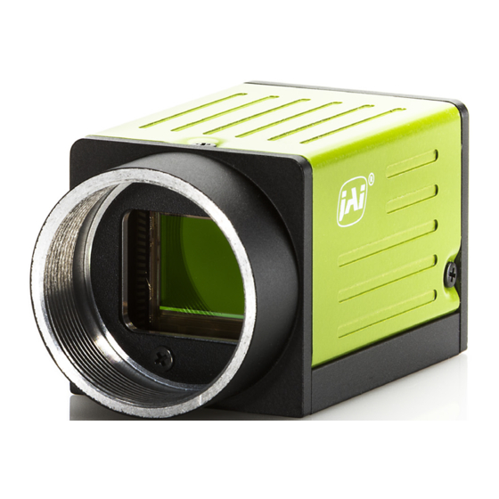
GO-5000M-PMCL-UV User Manual (Ver. 1.1) Parts Identification Parts Identification ① Lens Mount (C-Mount) ② POWER/TRIG LED ③ ④ Camera Link Connector 1 and 2 ⑤ Camera Locking Screw Holes (M3, 3mm depth) ① Lens Mount (C-Mount) Mount a C-mount lens, microscope adapter, etc. here. -
Page 14: ② Power/Trig Led
GO-5000M-PMCL-UV User Manual (Ver. 1.1) Parts Identification ② POWER/TRIG LED Indicates the power or trigger input status. Status Lit amber Camera initializing Lit green Camera in operation During operation in trigger mode, trigger signals are being input. Blinking Note: The blinking interval is not related to the actual input interval of the external green trigger. -
Page 15: ⑤ Camera Locking Screw Holes (M3, 3Mm Depth)
GO-5000M-PMCL-UV User Manual (Ver. 1.1) Parts Identification Camera Link Connector 2 Input Signal Description Output 1, 26 Power Power 2 (-), 15 (+) Y_OUT0 Data out 3 (-), 16 (+) Y_OUT1 Data out 4 (-), 17 (+) Y_OUT2 Data out... -
Page 16: Preparation
Save the current setting configurations in user memory. Short ASCII Commands The most universal method for controlling a Camera Link camera such as the GO-5000M-PMCL-UV is by the use of short ASCII commands sent via serial communications. All Camera Link frame grabber boards support the use of these short ASCII commands. -
Page 17: Step 1: Connect Devices
Later sections of the manual refer to GenICam nomenclature for various features/functions and includes a complete list of all camera settings starting. The GO-5000M-PMCL-UV fully supports applications written using GenICam-based SDKs. The advantage of this is that programs written using GenICam names can be applied with little or no modification to control cameras with other GenICam- compliant interfaces and even GenICam-compliant cameras from different vendors. -
Page 18: ① Lens
GO-5000M-PMCL-UV User Manual (Ver. 1.1) Preparation ① Lens C-mount lenses with lens mount protrusions of 10 mm or less can be attached. To prevent vignetting and to obtain the optimal resolution, use a lens that will cover the image sensor size. -
Page 19: ③ Camera Link Cable
GO-5000M-PMCL-UV User Manual (Ver. 1.1) Preparation ③ Camera Link Cable Connect the Camera Link cable to the Mini Camera Link connector. Use a cable that supports the Camera Link standard and is compatible with Mini Camera Link (SDR) connectors. Refer to the specifications of the cable for details on its bend radius. -
Page 20: Step 3: Verify The Connection Between The Camera And Pc
Start Bit: 1bit Stop Bit: 1 bit Parity: None Xon/Xoff Control: None 2. Enter the command DVN? <CR><LF> from the terminal emulator software. If correctly connected, response DVN = JAI Corporation will be displayed. Item Short ASCII Command Description DVN? <CR><LF>... -
Page 21: Step 4: Change The Camera Settings
GO-5000M-PMCL-UV User Manual (Ver. 1.1) Preparation Step 4: Change the Camera Settings This section explains how to change settings by describing the procedure for changing the output format as an example. Configure the Output Format Configure the size, position, and pixel format of the images to be acquired. The factory settings are as follows. -
Page 22: Step 5: Adjust The Image Quality
GO-5000M-PMCL-UV User Manual (Ver. 1.1) Preparation Example: Change the PixelFormat setting (ImageFormatControl) 1. To check the current PixelFormat setting, enter the command BA?<CR><LF> from the terminal emulator software. 2. To change the PixelFormat setting to Mono10, enter BA=1<CR><LF>. Step 5: Adjust the Image Quality Display the camera image and adjust the image quality. -
Page 23: Adjust The Black Level
GO-5000M-PMCL-UV User Manual (Ver. 1.1) Preparation Adjust the Black Level The black level can be set in the following range. GO-5000M-PMCL-UV: DigitalAll: -256 ~ +255 Short ASCII Item Values Command BlackLevelRawAll It can be set in the range from -256 to 255. -
Page 24: Save The User Settings
GO-5000M-PMCL-UV User Manual (Ver. 1.1) Preparation Save the User Settings 1. Stop image acquisition. Settings can only be saved when image acquisition on the camera is stopped. 2. Specify the storage location (UserSet1 - UserSet3) using the UserSetSave command and save the current camera settings. -
Page 25: Main Functions
GO-5000M-PMCL-UV User Manual (Ver. 1.1) Main Functions Main Functions This chapter describes the camera's main functions. Camera Link Interface Digital I/O 1 Camera Link Configuration Base Base Medium Full 80bit Camera Link port/bit 2Tap / 12bit 3Tap/8bit 4Tap / 12bit... - Page 26 GO-5000M-PMCL-UV User Manual (Ver. 1.1) Main Functions Digital I/O 2 (1/2) Camera Link Configuration Base Base Medium Full 80bit Camera Link port/bit 2Tap / 12bit 3Tap/8bit 4Tap / 12bit 8 Tap / 8bit 8 Tap / 10bit GenICam Tap Geometry...
- Page 27 GO-5000M-PMCL-UV User Manual (Ver. 1.1) Main Functions Digital I/O 2 (2/2) Camera Link Configuration Base Base Medium Full 80bit Camera Link port/bit 2Tap / 12bit 3Tap/8bit 4Tap / 12bit 8 Tap / 8bit 8 Tap / 10bit GenICam Tap Geometry...
- Page 28 I/O-1 connector. Camera Link pixel clock frequency In the GO-5000M-PMCL-UV, the Camera Link pixel clock can be selected from 84.99 MHz, 72.85 MHz, 58.28 MHz, and 48.57 MHz. If the 48.57MHz clock is used, the transfer length through the camera link cable will be extended to 10m for all tap geometries. On the other hand, the frame rate will be reduced (see table).
-
Page 29: Digital In/Out Interface
GO-5000M-PMCL-UV User Manual (Ver. 1.1) Main Functions Digital IN/OUT Interface On this camera, the software control tool can assign the necessary signals used in the system to digital inputs and outputs. Line Selector In the Line Selector, the following input and output signals can be assigned. - Page 30 Indicates the interface information of the input and output lines (Not connected, TTL, LVDS or Opto- coupled) Note: In the GO-5000M-PMCL-UV, Opto-coupled interface is not available. GPIO GPIO is a general interface for input and output which controls the I/O for trigger signals and other valid signals and pulse generators.
- Page 31 GO-5000M-PMCL-UV User Manual (Ver. 1.1) Main Functions Basic Block Diagram - 31 -...
- Page 32 GO-5000M-PMCL-UV User Manual (Ver. 1.1) Main Functions GPIO IN/OUT Matrix Trigger Selector Line Selector Pulse Generator Selector Trigger Source Source Signal NAND 1 In 1 NAND 1 In 2 NAND 2 In 1 NAND 2 In 2 Pulse Generator 0 (Frame Start ) ✓...
-
Page 33: Pulse Generator
In the Pulse Generator, various Clear settings are connected to GPIO. The following shows the Pulse Generator default settings. In the GO-5000M-PMCL-UV, the sensor pixel clock is 36 MHz for 8-bit, 28.8MHZ for 10-bit and 24 MHZ for 12-bit. - Page 34 GO-5000M-PMCL-UV User Manual (Ver. 1.1) Main Functions Pulse Generator Selector This is where you select a pulse generator. On this camera, it is fixed to Pulse Generator 0. Pulse Generator setting / Pulse Generator pulse construction Trigger Description Selector item...
- Page 35 GO-5000M-PMCL-UV User Manual (Ver. 1.1) Main Functions Pulse Generator Clear Activation Set the clear conditions of clear count pulse for the pulse generator. Pulse Generator Clear Sync Mode Set the count clear method for the pulse generator. In case of Async Mode, if the clear signal is input during the length setting value, the counter will stop counting according to the clear signal input.
- Page 36 GO-5000M-PMCL-UV User Manual (Ver. 1.1) Main Functions Pulse Generator Clear Source The following clear source can be selected as the pulse generator clear signal. Pulse Generator Description Clear Source Item Connect Low level signal to Clear Source for the pulse generator. Default setting High Connect High level signal to Clear Source for the pulse generator.
-
Page 37: Sensor Layout
GO-5000M-PMCL-UV User Manual (Ver. 1.1) Main Functions Display Name Value - Low - High - Frame Trigger Wait - Frame Active - Exposure Active - Pulse Generator Clear Source - Fval - Lval - CL_CC1_In - Nand0 Out - Nand1 Out... -
Page 38: Camera Output Format (Tap Geometry)
GO-5000M-PMCL-UV User Manual (Ver. 1.1) Main Functions Camera Output Format (Tap Geometry) Camera Output Format Bit Assignment 1X2–1Y 8-bit, 10-bit, 12-bit 1X3-1Y 8-bit 1X4–1Y 8-bit, 10-bit, 12-bit 1X8–1Y 8-bit, 10-bit Note: The camera output description is based on GenICam SFNC Ver.1.5.1. - Page 39 GO-5000M-PMCL-UV User Manual (Ver. 1.1) Main Functions 1X3-1Y 1X3–1Y is a 3-tap readout system specified in GenICam Tap Geometry. - 39 -...
- Page 40 GO-5000M-PMCL-UV User Manual (Ver. 1.1) Main Functions 1X4–1Y 1X4–1Y is a 4-tap readout system specified in GenICam Tap Geometry. - 40 -...
- Page 41 GO-5000M-PMCL-UV User Manual (Ver. 1.1) Main Functions 1X8–1Y 1X8–1Y is an 8-tap readout system and outputs as follows. - 41 -...
-
Page 42: Output Timing (Horizontal)
GO-5000M-PMCL-UV User Manual (Ver. 1.1) Main Functions Output Timing (Horizontal) The horizontal frequency is changed by setting the Tap Geometry. Horizontal timing per 1 tap in Camera Link output - 42 -... -
Page 43: 1X8-1Y (Lval Active/Non-Active, H Total)
GO-5000M-PMCL-UV User Manual (Ver. 1.1) Main Functions 1x8-1Y (LVAL Active/Non-Active, H Total) Horizontal timing parameters in continuous trigger mode (1/2) Camera Settings LVAL LVAL Binning H Total Active Camera Link Pixel Active Geometry Clock (Unit (Unit (Unit Width Offset X Height... -
Page 44: 1X4-1Y (Lval Active/Non-Active, H Total)
GO-5000M-PMCL-UV User Manual (Ver. 1.1) Main Functions 1x4-1Y (LVAL Active/Non-Active, H Total) Horizontal timing parameters in continuous trigger mode (1/2) Camera Settings LVAL LVAL Binning H Total Active Camera Link Pixel Active Geometry Clock (Unit (Unit (Unit Width Offset X Height... -
Page 45: 1X3-1Y (Lval Active/Non-Active, H Total)
GO-5000M-PMCL-UV User Manual (Ver. 1.1) Main Functions 1x3-1Y (LVAL Active/Non-Active, H Total) Horizontal timing parameters in continuous trigger mode (1/2) Camera Settings LVAL LVAL Binning H Total Active Camera Link Pixel Active Geometry Clock (Unit (Unit (Unit Width Offset X Height... -
Page 46: 1X2-1Y (Lval Active/Non-Active, H Total)
GO-5000M-PMCL-UV User Manual (Ver. 1.1) Main Functions 1x2-1Y (LVAL Active/Non-Active, H Total) Horizontal timing parameters in continuous trigger mode Camera Settings LVAL LVAL Binning H Total Active Camera Link Pixel Active Geometry Clock (Unit (Unit (Unit Width Offset X Height Offset Y Horizontal Vertical... -
Page 47: 1X8-1Y (1 Line Clock, Horizontal Frequency/Period)
GO-5000M-PMCL-UV User Manual (Ver. 1.1) Main Functions 1x8-1Y (1 Line Clock, Horizontal Frequency/Period) Horizontal timing parameters in continuous trigger mode (2/2) Note: A is Operation value and B is calculation value Camera Settings A: Operation value B: Calculation value Binning 1 line Total... - Page 48 GO-5000M-PMCL-UV User Manual (Ver. 1.1) Main Functions Camera Settings A: Operation value B: Calculation value Binning 1 line Total Horizontal Horizontal Camera Link clock (Unit: Frequency Period (Unit: Offset Offset Geometry Pixel Clock Width Height Horizontal Vertical clock) (Unit: kHz) 333.7...
- Page 49 GO-5000M-PMCL-UV User Manual (Ver. 1.1) Main Functions Camera Settings A: Operation value B: Calculation value Binning 1 line Total Horizontal Horizontal Camera Link clock (Unit: Frequency Period (Unit: Offset Offset Geometry Pixel Clock Width Height Horizontal Vertical clock) (Unit: kHz) 333.4...
- Page 50 GO-5000M-PMCL-UV User Manual (Ver. 1.1) Main Functions Camera Settings A: Operation value B: Calculation value Binning 1 line Total Horizontal Horizontal Camera Link clock (Unit: Frequency Period (Unit: Offset Offset Geometry Pixel Clock Width Height Horizontal Vertical clock) (Unit: kHz) 333.7...
-
Page 51: 1X4-1Y (1 Line Clock, Horizontal Frequency/Period)
GO-5000M-PMCL-UV User Manual (Ver. 1.1) Main Functions 1x4-1Y (1 Line Clock, Horizontal Frequency/Period) Horizontal timing parameters in continuous trigger mode (2/2) Note: A is Operation value and B is calculation value Camera Settings A: Operation value B: Calculation value Binning 1 line Total... - Page 52 GO-5000M-PMCL-UV User Manual (Ver. 1.1) Main Functions Camera Settings A: Operation value B: Calculation value Binning 1 line Total Horizontal Horizontal Camera Link clock (Unit: Frequency Period (Unit: Offset Offset Geometry Pixel Clock Width Height Horizontal Vertical clock) (Unit: kHz) 651.2...
- Page 53 GO-5000M-PMCL-UV User Manual (Ver. 1.1) Main Functions Camera Settings A: Operation value B: Calculation value Binning 1 line Total Horizontal Horizontal Camera Link clock (Unit: Frequency Period (Unit: Offset Offset Geometry Pixel Clock Width Height Horizontal Vertical clock) (Unit: kHz) 651.2...
-
Page 54: 1X3-1Y (1 Line Clock, Horizontal Frequency/Period)
GO-5000M-PMCL-UV User Manual (Ver. 1.1) Main Functions 1x3-1Y (1 Line Clock, Horizontal Frequency/Period) Horizontal timing parameters in continuous trigger mode (2/2) Note: A is Operation value and B is calculation value Camera Settings A: Operation value B: Calculation value Binning 1 line Total... -
Page 55: 1X2-1Y (1 Line Clock, Horizontal Frequency/Period)
GO-5000M-PMCL-UV User Manual (Ver. 1.1) Main Functions 1x2-1Y (1 Line Clock, Horizontal Frequency/Period) Horizontal timing parameters in continuous trigger mode (2/2) Note: A is Operation value and B is calculation value Camera Settings A: Operation value B: Calculation value Binning 1 line Total... - Page 56 GO-5000M-PMCL-UV User Manual (Ver. 1.1) Main Functions Camera Settings A: Operation value B: Calculation value Binning Camera Link 1 line Total Horizontal Horizontal Offset Offset Geometry Pixel Clock clock (Unit: Frequency Period (Unit: Width Height Horizontal Vertical clock) (Unit: kHz) 1293.2...
- Page 57 GO-5000M-PMCL-UV User Manual (Ver. 1.1) Main Functions Camera Settings A: Operation value B: Calculation value Binning Camera Link 1 line Total Horizontal Horizontal Offset Offset Geometry Pixel Clock clock (Unit: Frequency Period (Unit: Width Height Horizontal Vertical clock) (Unit: kHz) 1294.9...
-
Page 58: Output Timing (Vertical)
GO-5000M-PMCL-UV User Manual (Ver. 1.1) Main Functions Output Timing (Vertical) The below figure shows the vertical timing of Camera Link output during continuous trigger operation. However, with 1X8-1Y 10-bit geometry, which is 80-bit configuration, DVAL and Exposure Active, which are normally output to Camera Link spare bits, are not output through the Camera Link interface as data bits are applied to those bits. -
Page 59: 1X8-1Y (Fval, Dval, V-Offset, Exposure Time)
GO-5000M-PMCL-UV User Manual (Ver. 1.1) Main Functions 1x8-1Y (FVAL, DVAL, V-Offset, Exposure Time) Vertical format (in Continuous trigger mode) (1/2) Camera Settings FVAL & FVAL Exposure Binning Frame DVAL V-Offset Pixel Time Period Active Active (Unit: Geometry Clock (min) (Typ) -
Page 60: 1X4-1Y (Fval, Dval, V-Offset, Exposure Time)
GO-5000M-PMCL-UV User Manual (Ver. 1.1) Main Functions 1x4-1Y (FVAL, DVAL, V-Offset, Exposure Time) Vertical format (in Continuous trigger mode) (1/2) Camera Settings FVAL & FVAL Exposure Binning Frame DVAL V-Offset Pixel Time Period Active Active (Unit: Geometry Clock (min) (Typ) -
Page 61: 1X3-1Y (Fval, Dval, V-Offset, Exposure Time)
GO-5000M-PMCL-UV User Manual (Ver. 1.1) Main Functions 1x3-1Y (FVAL, DVAL, V-Offset, Exposure Time) Vertical format (in Continuous trigger mode) (1/2) Camera Settings FVAL & FVAL Exposure Binning Frame DVAL V-Offset Pixel Time Period Active Active (Unit: Geometry Clock (min) (Typ) -
Page 62: 1X2-1Y (Fval, Dval, V-Offset, Exposure Time)
GO-5000M-PMCL-UV User Manual (Ver. 1.1) Main Functions 1x2-1Y (FVAL, DVAL, V-Offset, Exposure Time) Vertical format (in Continuous trigger mode) (1/2) Camera Settings FVAL & FVAL Exposure Binning Frame DVAL V-Offset Pixel Time Period Active Active (Unit: Geometry Clock (min) (Typ) -
Page 63: 1X8-1Y (Frame Period, Exposure Time, Exposure End To Fval Active Start)
GO-5000M-PMCL-UV User Manual (Ver. 1.1) Main Functions 1x8-1Y (Frame Period, Exposure Time, Exposure End to FVAL Active Start) Vertical format (in Continuous trigger mode) (2/2) Camera Settings Exposure Binning Frame Frame Exposure End to Pixel Period Period Time FVAL Geometry... -
Page 64: 1X4-1Y (Frame Period, Exposure Time, Exposure End To Fval Active Start)
GO-5000M-PMCL-UV User Manual (Ver. 1.1) Main Functions 1x4-1Y (Frame Period, Exposure Time, Exposure End to FVAL Active Start) Vertical format (in Continuous trigger mode) (2/2) Camera Settings Exposure Binning Frame Exposure End to Frame Pixel Period Time FVAL Period Geometry... -
Page 65: 1X3-1Y (Frame Period, Exposure Time, Exposure End To Fval Active Start)
GO-5000M-PMCL-UV User Manual (Ver. 1.1) Main Functions 1x3-1Y (Frame Period, Exposure Time, Exposure End to FVAL Active Start) Vertical format (in Continuous trigger mode) (2/2) Camera Settings Exposure Binning Frame Exposure End to Frame Pixel Period Time FVAL Period Geometry... -
Page 66: 1X2-1Y (Frame Period, Exposure Time, Exposure End To Fval Active Start)
GO-5000M-PMCL-UV User Manual (Ver. 1.1) Main Functions 1x2-1Y (Frame Period, Exposure Time, Exposure End to FVAL Active Start) Vertical format (in Continuous trigger mode) (2/2) Camera Settings Exposure Binning Frame Exposure End to Frame Pixel Period Time FVAL Period Geometry... -
Page 67: Roi (Region Of Interest) Settings
GO-5000M-PMCL-UV User Manual (Ver. 1.1) Main Functions ROI (Region of Interest) Settings On this camera, a subset of the image can be output by setting Width, Height, Offset- X, and Offset-Y. If the height is decreased, the number of lines read out is decreased and as the result, the frame rate is increased. -
Page 68: Acquisition Control
GO-5000M-PMCL-UV User Manual (Ver. 1.1) Main Functions Acquisition Control With Trigger OFF (free running mode), the default frame rate of the camera is based on the specified ROI. The smaller the ROI, the faster the default frame rate. However, it is possible to specify a free- running frame rate (i.e., no trigger needed) that is slower than the default rate. - Page 69 GO-5000M-PMCL-UV User Manual (Ver. 1.1) Main Functions Figures for A to E by the Tap Geometry CL Clock Max. Frame Rate Tap Geometry Frequency (MHz) (fps)* 84.99(High) 169.9999 31.9 1X2-1Y 72.85(Mid) 145.7142 27.4 48.57(Low) 97.1428 18.3 84.99(High) 254.99985 47.8 1X3-1Y 72.85(Mid)
-
Page 70: Exposure Settings
GO-5000M-PMCL-UV User Manual (Ver. 1.1) Main Functions Exposure Settings This section describes how to set the exposure settings. Command Name Parameter Description Shutter control is not available. The exposure time depends on the frame rate. Exposure Mode Timed The exposure is set by ExposureTime. - Page 71 If the trigger is used, it uses “Frame Start”. The procedure is; 1. Select “Frame Start” in “Trigger Selector” Note: In the GO-5000M-PMCL-UV, only “Frame Start” is available. 2. Select “Timed” or “Trigger Width” in “Exposure Mode”. 3. Set “ON” in “Trigger Mode”.
- Page 72 GO-5000M-PMCL-UV User Manual (Ver. 1.1) Main Functions ExposureAuto This is a function to control the exposure automatically. It is effective only for Timed. JAI ALC Reference controls the brightness. There are two modes, OFF and Continuous. OFF: No exposure control Continuous: Exposure continues to be adjusted automatically In this mode, the following settings are available.
-
Page 73: Trigger Control
GO-5000M-PMCL-UV User Manual (Ver. 1.1) Main Functions Trigger Control The following 5 types of Trigger Control are available by the combination of Trigger Selector, Trigger Mode, Exposure Mode and Trigger Option. Camera Settings JAI Custom Trigger Description Trigger Trigger Exposure... - Page 74 GO-5000M-PMCL-UV User Manual (Ver. 1.1) Main Functions Trigger Source Select the trigger source to be used for trigger operation (Frame Start) from the following: Trigger Source Description Item Connect LOW level signal to the selected trigger operation (Default setting) High Connect HIGH level signal to the selected trigger operation Connect Soft Trigger signal to the selected trigger operation.
-
Page 75: Normal Continuous Operation
GO-5000M-PMCL-UV User Manual (Ver. 1.1) Main Functions Normal Continuous Operation This is used for applications which do not require triggering. Minimum interval (1X8–1Y, 8-bit, CL Clock =72.85MHz) Trigger Mode Readout Mode Time (Min. Frame Period) Full 9435us AOI Center 2/3... -
Page 76: Timed Mode
GO-5000M-PMCL-UV User Manual (Ver. 1.1) Main Functions Timed Mode This mode captures image(s) with a preset exposure time by using the external trigger. An additional setting determines if the trigger pulse can be accepted during the exposure period. Primary settings to use this mode... -
Page 77: Trigger Width Mode
GO-5000M-PMCL-UV User Manual (Ver. 1.1) Main Functions Trigger Width Mode In this mode, the exposure time is equal to the trigger pulse width. Accordingly, longer exposure times are supported. Additional settings determine if the trigger pulse can be accepted during the exposure period. -
Page 78: Rct Mode
GO-5000M-PMCL-UV User Manual (Ver. 1.1) Main Functions RCT Mode Until the trigger is input, the camera operates continuously and can use auto-gain, if necessary, to control the exposure setting. During this time, FVAL and LVAL are output but DVAL is not output. -
Page 79: Rct Mode Together With Alc Function
GO-5000M-PMCL-UV User Manual (Ver. 1.1) Main Functions RCT Mode Together with ALC Function RCT mode can use ALC control to ensure that the proper exposure is set when the trigger pulse is input. In this case, the following settings are additionally required to RCT mode settings. -
Page 80: Sequence Mode
This is a function to capture images in sequence based on preset ROI, Exposure Time, Gain and other parameters in the sequence index table. To use sequence mode, Video Send Mode must be set to “Command Sequence.” In the GO-5000M-PMCL-UV, this is the only sequence mode available. Video Send Mode... -
Page 81: Trigger Sequence Mode Timing
GO-5000M-PMCL-UV User Manual (Ver. 1.1) Main Functions Trigger Sequence Mode Timing The following drawing shows the sequence mode timing concept. In this mode, it is not possible to overlap the next exposure while the previous trigger operation (Index table) is in progress. -
Page 82: Descriptions Of Index Table Parameters
GO-5000M-PMCL-UV User Manual (Ver. 1.1) Main Functions Descriptions of Index Table Parameters Sequence Mode Command Command Parameter Description Sequence ROI Index Index 1 ~ 10 Select an index to be set <Set to each Index> Sequence ROI Frame 1 ~ 255... -
Page 83: Multi Roi Function
GO-5000M-PMCL-UV User Manual (Ver. 1.1) Main Functions Multi ROI Function This function divides one frame image into a maximum of 5 images vertically and reads out all areas in one frame. In this function, width is the same for all 5 images. In the GO-5000M-PMCLUV, image overlapping is not possible. - Page 84 GO-5000M-PMCL-UV User Manual (Ver. 1.1) Main Functions ROI setting explanation if Multi ROI Index Max is set to 4 Video output of Multi ROI Note: In this mode, the frame grabber board must set its horizontal pixel number to Multi ROI Width and its vertical pixels to Multi ROI Max and the sum of Multi ROI Height.
-
Page 85: Operation And Function Matrix
GO-5000M-PMCL-UV User Manual (Ver. 1.1) Main Functions Operation and Function Matrix Vide Send Mode Trigger Trigger Binning Binning Exposure Auto Auto Over Exposureoperation Multi Sequence Mode Option Vertical Horizontal Time Gain Exposure ✓ ✓ ✓ ✓ ✓ ✓ ✓ ✓... -
Page 86: Black Level Control
GO-5000M-PMCL-UV User Manual (Ver. 1.1) Main Functions Black Level Control This function adjusts the setup level. Reference Level 33.5LSB (Average of 100 x 100 pixels) Video Level Variable Range 0 ~ approx.100 LSB Variable Range -256 ~ 255 (Default: 0) Resolution 1STEP=0.25LSB... -
Page 87: Gain Control
GO-5000M-PMCL-UV User Manual (Ver. 1.1) Main Functions Gain Control On this camera, the gain control uses Analog Base Gain and Digital Gain. Analog Base Gain can be set at 0dB, +6dB or +12dB. The digital gain is used for the master gain setting. - Page 88 The range for adjustment: Gain Raw Digital All: 100 ~ 1600 (0dB ~ 24dB) This provides automatic control of the gain level. Gain Auto This provides automatic control of the gain level. This is controlled by the command JAI ALC Reference. OFF: Adjust manually.
-
Page 89: Lut (Lookup Table)
GO-5000M-PMCL-UV User Manual (Ver. 1.1) Main Functions LUT (Lookup Table) This function can be used to convert the input to the desired output characteristics. The Lookup Table (LUT) has 32 points for setup on this camera. The output level is created by applying gain to the input level to achieve the specified output level. -
Page 90: Gamma
GO-5000M-PMCL-UV User Manual (Ver. 1.1) Main Functions Gamma This command is used to set gamma 0.45, gamma 0.6 and gamma 1.0 (OFF) in 3 steps. The gamma value is an approximate value. Linear and Dark Compression This camera has a dark compression circuit to improve the signal-to-noise ratio in the dark portion of the image. -
Page 91: Shading Correction
GO-5000M-PMCL-UV User Manual (Ver. 1.1) Main Functions Shading Correction This function compensates for shading (non-uniformity) caused by the lens or the light source used. This compensation can be performed even if shading issues are not symmetrical in horizontal and/or vertical directions. There are two methods of correction. -
Page 92: Alc (Automatic Level Control)
GO-5000M-PMCL-UV User Manual (Ver. 1.1) Main Functions ALC (Automatic Level Control) On this camera, auto gain and auto exposure can be combined to provide a wide ranging automatic exposure control from dark to bright or vice versa. The functions are applied in the sequence shown below and if one function is disabled, the remaining function will work independently. -
Page 93: Hdr (High Dynamic Range)
GO-5000M-PMCL-UV User Manual (Ver. 1.1) Main Functions HDR (High Dynamic Range) HDR sensing mode can be set when HDR Mode is set to ON while Exposure Mode is Timed. The parameters to configure dynamic range are HDR_SLOPE Level 1, Level 2, Level 3 and Level 4. -
Page 94: Miscellaneous
GO-5000M-PMCL-UV User Manual (Ver. 1.1) Miscellaneous Miscellaneous External Appearance and Dimensions Notes: Dimensional tolerance: ± 0.3mm Unit: mm - 94 -... -
Page 95: Spectral Response
GO-5000M-PMCL-UV User Manual (Ver. 1.1) Miscellaneous Spectral Response - 95 -... -
Page 96: Specifications
GO-5000M-PMCL-UV User Manual (Ver. 1.1) Miscellaneous Specifications Specifications Description Scanning system Progressive scan Synchronization Internal Interface CameraLink Specifications (V.2.0 RC2), Conforming with PoCL specifications Image sensor 1-inch Monochrome CMOS Aspect Ratio Image size (Effective Image) 12.8 (h) x 10.24 (v) mm, 16.39 mm diagonal Pixel size 5 (h) x 5 (v) μm... - Page 97 GO-5000M-PMCL-UV User Manual (Ver. 1.1) Miscellaneous Specifications Description H1, V1 63.6fps H1, V2 126.1fps H1, V4 248.2fps H2, V1 71.7fps 1X4–1Y 8/10/12-bit CL clock: HIGH H2, V2 142.3fps Binning H2, V4 280.1fps H4, V1 71.7fps H4, V2 142.3fps H4, V4 280.1fps...
- Page 98 GO-5000M-PMCL-UV User Manual (Ver. 1.1) Miscellaneous Specifications Description 8 ~ 2560 pixels, 8 pixels/step(1X2-1Y) 8 ~ 2560 pixels, 8 pixels/step(1X3-1Y) Width 8 ~ 2560 pixels, 8 pixels/step(1X4-1Y) 8 ~ 2560 pixels, 8 pixels/step(1X8-1Y) 0 ~ 2552 pixels, 8 pixels/step(1X2-1Y) 0 ~ 2552 pixels, 8 pixels/step(1X3-1Y)
- Page 99 GO-5000M-PMCL-UV User Manual (Ver. 1.1) Miscellaneous Specifications Description Detect white blemish above the threshold value (Black Detection blemish is detected only by factory) Blemish Comp. Complement by adjacent pixels (Continuous blemishes are Compensation not compensated) Numbers Up to 512 pixels...
-
Page 100: Appendix
GO-5000M-PMCL-UV User Manual (Ver. 1.1) Miscellaneous Appendix Precautions Personnel not trained in dealing with similar electronic devices should not service this camera. The camera contains components sensitive to electrostatic discharge. The handling of these devices should follow the requirements of electrostatic sensitive components. - Page 101 GO-5000M-PMCL-UV User Manual (Ver. 1.1) Miscellaneous Caution When Mounting a Lens on the Camera When mounting a lens on the camera dust particles in the air may settle on the surface of the lens or the image sensor of the camera. It is therefore important to keep the protective caps on the lens and on the camera until the lens is mounted.
-
Page 102: Short Ascii Command Communication Protocol
GO-5000M-PMCL-UV User Manual (Ver. 1.1) Short ASCII Command Communication Protocol Short ASCII Command Communication Protocol This chapter describes the communication control protocol based on the short ASCII command as the reference. Communication Setting Baud Rate: 9600 Data Length: 8bit Start Bit: 1bit... -
Page 103: Gencp Bootstrap Register
GO-5000M-PMCL-UV User Manual (Ver. 1.1) Short ASCII Command Communication Protocol Switching baud rate between PC and camera Camera always starts up with 9600bps. This can be switched to higher baud rates after a communication has been established. When switching to other baud rate the procedure is as follows. -
Page 104: Technology Specific Bootstrap Register
GO-5000M-PMCL-UV User Manual (Ver. 1.1) Short ASCII Command Communication Protocol Technology Specific Bootstrap Register Short Name Interface Access Values MIN MAX Default Description ASCII Indicate Support/Non- support status for each baud rate SupportedBaud I Integer SBDRT 0x01 0xFF 0x1F SBDRT?<CR><LF>... -
Page 105: Image Format Control
GO-5000M-PMCL-UV User Manual (Ver. 1.1) Short ASCII Command Communication Protocol Image Format Control Short Name Interface Access Values MIN MAX Default Description ASCII Min ~ HTL=[Param.]<CR>< LF> Height I Integer 2048 2048 HTL?<CR><LF> (Max - OffsetY) Min ~ WTC=[Param.]<CR><LF> Width... -
Page 106: Acquisition Control
GO-5000M-PMCL-UV User Manual (Ver. 1.1) Short ASCII Command Communication Protocol Acquisition Control Short Name Interface Access Values MIN MAX Default Description ASCII FrameStartTrig TM=[Param.]<CR><LF> Off/On Mode Enumeration TM?<CR><LF> TriggerSoftware I Command (R)/W STRG 0, 1 STRG=0<CR><LF> 0: Low 1: High... -
Page 107: Analog Control
GO-5000M-PMCL-UV User Manual (Ver. 1.1) Short ASCII Command Communication Protocol Analog Control Short Name Interface Access Values MIN MAX Default Description ASCII min ~ 0 ~ FGA=[Param.]<CR><L F> GainRawDigital All I Integer 1600 FGA?<CR><LF> 0: 0dB ABALL=[Param.]<CR><L F> AnalogBaseGainAll I Integer... -
Page 108: Digital Io Control
GO-5000M-PMCL-UV User Manual (Ver. 1.1) Short ASCII Command Communication Protocol Digital IO Control Short Name Interface Access Values MIN MAX Default Description ASCII LineInverter_ ND0INV1=[Param.]<CR><LF> I Boolean ND0INV1 False/True Nand0In1 ND0INV1?<CR><LF> LineInverter_ ND0INV2=[Param.]<CR><LF> I Boolean ND0INV2 False/True Nand0In2 ND0INV2?<CR><LF> LineInverter_ ND1INV1=[Param.]<CR><LF>... -
Page 109: Lut Control
GO-5000M-PMCL-UV User Manual (Ver. 1.1) Short ASCII Command Communication Protocol LUT Control Short Name Interface Access Values MIN MAX Default Description ASCII LUTG=[Param1],[Para Param 1: LUT index m2]<CR><LF> LUTValueGreen γ=1 Param 2: LUTdata I Integer LUTG (Mono) equivalent LUTG?[Param1]<CR>< (min ~ max) LF>... -
Page 110: Jai Custom
GO-5000M-PMCL-UV User Manual (Ver. 1.1) Short ASCII Command Communication Protocol JAI Custom Short Name Interface Access Values MIN MAX Default Description ASCII AR=[Param.]<CR><LF> AR?<CR><LF> AcquisitionFrame Maximum value is I Integer Min ~ Max[us] 325786 11961 Period calcurated depending on Height and Offset Y... - Page 111 GO-5000M-PMCL-UV User Manual (Ver. 1.1) Short ASCII Command Communication Protocol Short Name Interface Access Values MIN MAX Default Description ASCII 0: Normal 1: Trigger Sequence I Enumera VSM=[Param.]<CR><LF> VideoSendMode 2: Command tion VSM?<CR><LF> Sequence 3: Multi Roi Mode SQF1= SequenceMode...
- Page 112 GO-5000M-PMCL-UV User Manual (Ver. 1.1) Short ASCII Command Communication Protocol Short Name Interface Access Values MIN MAX Default Description ASCII SQH(n)= SequenceMode I Integer SQH(n) Min ~ Max 2048 2048 [Param.]<CR><LF> SQH Height(n-1) (n)?<CR><LF> SQH128= SequenceMode I Integer SQH128 Min ~ Max...
- Page 113 GO-5000M-PMCL-UV User Manual (Ver. 1.1) Short ASCII Command Communication Protocol Short Name Interface Access Values MIN MAX Default Description ASCII SQPE3= SequenceMode I Integer SQPE3 Min ~ Max 8000000 18000 [Param.]<CR><LF> ExposureTime2 SQPE3?<CR><LF> SequenceMode I Integer SQPE(n) Min ~ Max 8000000 18000 SQPE(n)=[Param.]<CR>...
- Page 114 GO-5000M-PMCL-UV User Manual (Ver. 1.1) Short ASCII Command Communication Protocol Short Name Interface Access Values MIN MAX Default Description ASCII SQLUT2= SequenceMode I Enumera SQLUT 2 Off/On [Param.]<CR><LF> LutEnable1 tion SQLUT2?<CR><LF> SQLUT3= SequenceMode I Enumera SQLUT 3 Off/On [Param.]<CR><LF> LutEnable2 tion SQLUT3?<CR><LF>...
- Page 115 GO-5000M-PMCL-UV User Manual (Ver. 1.1) Short ASCII Command Communication Protocol Short Name Interface Access Values MIN MAX Default Description ASCII MRH1= MultiRoiHeight1 I Integer MRH1 Min ~ Max 2048 2048 [Param.]<CR><LF> MRH1?<CR><LF> MRH2= MultiRoiHeight2 I Integer MRH2 Min ~ Max 2048 [Param.]<CR><LF>...
- Page 116 GO-5000M-PMCL-UV User Manual (Ver. 1.1) Short ASCII Command Communication Protocol Short Name Interface Access Values MIN MAX Default Description ASCII MROY5= MultiRoiOffsetY5 I Integer MROY5 Min ~ Max 2047 [Param.]<CR><LF> MROY5?<CR><LF> 0: Off LUTC= I Enumera LUTMode LUTC 1: Gamma [Param.]<CR><LF>...
- Page 117 GO-5000M-PMCL-UV User Manual (Ver. 1.1) Short ASCII Command Communication Protocol Short Name Interface Access Values MIN MAX Default Description ASCII 0=Complete. 1=Too Bright. 2=Too dark RequestGainAuto I Enumera 3=Timeout Error AGRS AGRS?<CR><LF> Result tion 4=Busy. 5=Limit. 6= Trig is not set as Normal.
- Page 118 GO-5000M-PMCL-UV User Manual (Ver. 1.1) Short ASCII Command Communication Protocol Short Name Interface Access Values MIN MAX Default Description ASCII ALCChannelArea I Enumera ALCHML 0: Off / 1: On ALC**= HighMidLeft tion [Param.]<CR><LF> ALCChannelArea I Enumera ALC**?<CR><LF> ALCHL 0: Off / 1: On...
- Page 119 GO-5000M-PMCL-UV User Manual (Ver. 1.1) Short ASCII Command Communication Protocol Short Name Interface Access Values MIN MAX Default Description ASCII 0: Low 1: High 2:Soft AcquisitionTriggerWait PGIN= 4: FrameTriggerWait GpioPulseGenIn I Enumera PGIN [Param.]<CR><LF> put0 tion 5: FrameActive PGIN?<CR><LF> 6: ExposureActive...
- Page 120 GO-5000M-PMCL-UV User Manual (Ver. 1.1) Short ASCII Command Communication Protocol Short Name Interface Access Values MIN MAX Default Description ASCII IND0INV2= 0:Non-Inv GpioNand0Input I Enumera [Param.]<CR><LF> IND0INV 2 Invert2 tion 1:Inv IND0INV2?<CR><LF> IND1INV2= GpioNand1Input I Enumera [Param.]<CR><LF> IND1INV 2 Same as above.
-
Page 121: User's Record
GO-5000M-PMCL-UV User Manual (Ver. 1.1) User's Record User's Record Model name: GO-5000M-PMCL-UV Revision: …………… Serial No: …………… Firmware version: …………… For camera revision history, please contact your local JAI distributor. - 121 -... -
Page 122: Revision History
GO-5000M-PMCL-UV User Manual (Ver. 1.1) Revision History Revision History Revision Date Changes 2022/11/17 Redesigned the User Manual. Feb 2021 First Release Trademarks Other systems and product names described in this document are trademarks or registered trademarks of their respective owners. The ™ and ®...
Need help?
Do you have a question about the GO-5000M-PMCL-UV and is the answer not in the manual?
Questions and answers