Table of Contents
Advertisement
Quick Links
User Manual
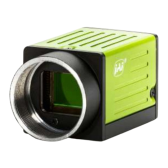
GO-5000M-PGE
GO-5000M-PGE-UV
CMOS Digital Progressive Scan
Monochrome and Monochrome UV Camera with GigE Interface
Document Version: 2.0
GO-5000M-PGE_Manual_Ver.2.0_2023-04-26
Thank you for purchasing this product.
Be sure to read this documentation before use.
This documentation includes important safety precautions and instructions on how to operate the unit. Be sure to read this documentation to ensure
proper operation.
The contents of this documentation are subject to change without notice for the purpose of improvement.
© 2023 JAI
Advertisement
Table of Contents

Related Manuals for JAI GO-5000M-PGE


Summary of Contents for JAI GO-5000M-PGE
- Page 1 This documentation includes important safety precautions and instructions on how to operate the unit. Be sure to read this documentation to ensure proper operation. The contents of this documentation are subject to change without notice for the purpose of improvement. © 2023 JAI...
-
Page 2: Table Of Contents
GO-5000M-PGE | GO-5000M-PGE-UV | User Manual (Ver. 2.0) Table of Contents Table of Contents Table of Contents About Technical Note Notice/Warranty Notice Warranty Certifications CE Compliance Warning Supplement Usage Precautions Notes on Cable Configurations Notes on LAN Cable Connection Notes on Attaching the Lens... - Page 3 GO-5000M-PGE | GO-5000M-PGE-UV | User Manual (Ver. 2.0) Table of Contents ① Lens ② Direct Mounting (or Use MP-43 Tripod Adapter Plate) ③ LAN Cable ➃ Network Card ⑤ DC IN / Trigger IN Connection Cable ⑥ AC Adapter (Power Supply) (If Necessary)
- Page 4 GO-5000M-PGE | GO-5000M-PGE-UV | User Manual (Ver. 2.0) Table of Contents Acquisition Stop Acquisition Frame Rate Calculation of the Maximum Frame Rate Exposure Mode Trigger Control Normal Continuous Operation Timed Mode Trigger Width Mode RCT (Reset Continuous Trigger) Mode Video Send Mode...
-
Page 5: About Technical Note
Table of Contents About Technical Note Some additional technical information is provided on the JAI website as Technical Notes. In this manual, if a technical note is available for a particular topic, the above icon is shown. Please refer to the following URL for Technical notes. -
Page 6: Notice/Warranty
The material contained in this manual consists of information that is proprietary to JAI Ltd., Japan, and may only be used by the purchasers of the product. JAI Ltd., Japan makes no warranty for the use of its product and assumes no responsibility for any errors which may appear or for damages resulting from the use of the information contained herein. -
Page 7: Warning
GO-5000M-PGE | GO-5000M-PGE-UV | User Manual (Ver. 2.0) Notice/Warranty Connect the equipment into an outlet on a circuit different from that to which the receiver is connected. Consult the dealer or an experienced radio/TV technician for help. Warning Changes or modifications to this unit not expressly approved by the party responsible for FCC compliance could void the user’s authority to operate the equipment. -
Page 8: Supplement
GO-5000M-PGE | GO-5000M-PGE-UV | User Manual (Ver. 2.0) Notice/Warranty Supplement The following statement is related to the regulation on “Measures for the Administration of the Control of Pollution by Electronic Information Products “, known as “China RoHS“. The table shows contained Hazardous Substances in this camera. -
Page 9: Usage Precautions
GO-5000M-PGE | GO-5000M-PGE-UV | User Manual (Ver. 2.0) Usage Precautions Usage Precautions Notes on Cable Configurations The presence of lighting equipment and television receivers nearby may result in video noise. In such cases, change the cable configurations or placement. Notes on LAN Cable Connection Secure the locking screws on the connector manually, and do not use a driver. -
Page 10: Phenomena Specific To Cmos Image Sensors
GO-5000M-PGE | GO-5000M-PGE-UV | User Manual (Ver. 2.0) Usage Precautions Phenomena Specific to CMOS Image Sensors The following phenomena are known to occur on cameras equipped with CMOS image sensors. These do not indicate malfunctions. Aliasing: When shooting straight lines, stripes, and similar patterns, vertical aliasing (zigzag distortion) may appear on the monitor. -
Page 11: Features
Features This camera is an industrial progressive scan camera equipped with a Type 1 global shutter CMOS image sensor with 5.2 effective megapixels (2560 × 2048). The GO-5000M-PGE-UV model has sensitivity in the UV region. The unit is compact and lightweight in design and is equipped with GigE Vision Ver2.0 interface. - Page 12 GO-5000M-PGE | GO-5000M-PGE-UV | User Manual (Ver. 2.0) Features Gamma correction (3 steps: 0.45, 0.6 and 1.0) Blemish compensation HDR (High Dynamic Range) function C-mount for lens mount - 12 -...
-
Page 13: Parts Identification
GO-5000M-PGE | GO-5000M-PGE-UV | User Manual (Ver. 2.0) Parts Identification Parts Identification ① Lens Mount (C-Mount) ② RJ-45 Connector ③ POWER/TRIG LED ④ LINK LED ⑤ ACT LED ⑥ DC IN/TRIG Connector (6-Pin Round) ⑦ Mounting Holes (M3, 3mm depth) ① Lens Mount (C-Mount) Mount a C-mount lens, microscope adapter, etc. - Page 14 GO-5000M-PGE | GO-5000M-PGE-UV | User Manual (Ver. 2.0) Parts Identification GigE Vision イ ンタ ーフ ェ イ ス 入 出 力 信 号 Pin No. In/Out MX1+ (DA+) MX1– (DA–) In/Out MX2+ (DB+) In/Out MX3+ (DC+) In/Out RJ45 (固 定 ネジ付 き) MX3–...
-
Page 15: ③ Power/Trig Led
GO-5000M-PGE | GO-5000M-PGE-UV | User Manual (Ver. 2.0) Parts Identification ③ POWER/TRIG LED Indicates the power or trigger input status. Status Lit amber Camera initializing Lit green Camera in operation During operation in trigger mode, trigger signals are being input. -
Page 16: ⑥ Dc In/Trig Connector (6-Pin Round)
GO-5000M-PGE | GO-5000M-PGE-UV | User Manual (Ver. 2.0) Parts Identification ⑥ DC IN/TRIG Connector (6-Pin Round) Connect the cable for a power supply (optional) or for DC IN / trigger IN here. Camera Side: HR10A-7R-6PB (73) (Hirose Electric or equivalent) Cable Side: HR10A-7P-6S (Plug) (Hirose Electric or equivalent) Pin No. -
Page 17: Preparation
Read this section to learn how the camera connects to devices and accessories. The preparation process is described below. Step 1: Install the Software (First Time Only) Install the software for configuring and controlling the camera (eBUS SDK for JAI) on the computer. Step 2: Connect Devices Connect the lens, LAN cable, AC adapter, computer, and other devices. -
Page 18: Step 1: Install The Software (First Time Only)
When using the camera for the first time, install the software for configuring and controlling the camera (eBUS SDK for JAI) on the computer. Note: When you install eBUS SDK for JAI, eBUS Player for JAI will also be installed. 1. Download the eBUS SDK for JAI from the JAI website (https://www.jai.com/support-software/jai-... -
Page 19: ① Lens
GO-5000M-PGE | GO-5000M-PGE-UV | User Manual (Ver. 2.0) Preparation ① Lens C-mount lenses with lens mount protrusions of 10 mm or less can be attached. To prevent vignetting and to obtain the optimal resolution, use a lens that will cover the image sensor size. -
Page 20: ③ Lan Cable
GO-5000M-PGE | GO-5000M-PGE-UV | User Manual (Ver. 2.0) Preparation ③ LAN Cable Connect a LAN cable to the RJ-45 connector. Use a LAN cable that is Category 5e or higher (Category 6 recommended). Use a LAN cable that is an STP cable. -
Page 21: Step 3: Verify Camera Operation
GO-5000M-PGE | GO-5000M-PGE-UV | User Manual (Ver. 2.0) Preparation Step 3: Verify Camera Operation When power is supplied to the camera while the necessary equipment is connected, the POWER/TRIG LED at the rear of the camera lights amber, and initialization of the camera starts. - Page 22 GO-5000M-PGE | GO-5000M-PGE-UV | User Manual (Ver. 2.0) Preparation 2. Select the camera you want to configure. Click the Select / Connect button. 3. The connected camera is listed. Please select one camera and click OK. - 22 -...
- Page 23 GO-5000M-PGE | GO-5000M-PGE-UV | User Manual (Ver. 2.0) Preparation 4. Check that the settings of the selected camera are displayed. 5. Click the Device control button. The screen shown below will be displayed. In this window, you can adjust various settings of the camera.
-
Page 24: Step 5: Change The Camera Settings
GO-5000M-PGE | GO-5000M-PGE-UV | User Manual (Ver. 2.0) Preparation Step 5: Change the Camera Settings This section explains how to change settings by describing the procedure for changing the output format as an example. Configure the Output Format Configure the size, position, and pixel format of the images to be acquired. The factory settings are as follows. -
Page 25: Step 6: Adjust The Image Quality
GO-5000M-PGE | GO-5000M-PGE-UV | User Manual (Ver. 2.0) Preparation Step 6: Adjust the Image Quality Display the camera image and adjust the image quality. Display the Image Display the image captured by the camera. When you click the Play button, the camera image appears in the right area. -
Page 26: Adjust The Gain
GO-5000M-PGE | GO-5000M-PGE-UV | User Manual (Ver. 2.0) Preparation Adjust the Gain You can adjust Gain manually or automatically. Manual Adjustment 1. Open AnalogControl and set GainAuto to Off (Default). 2. Configure the Gain setting. 1. Set AnalogBaseGain (Select from 0dB, +6dB and +12dB). -
Page 27: Adjust The Black Level
GO-5000M-PGE | GO-5000M-PGE-UV | User Manual (Ver. 2.0) Preparation Adjust the Black Level 1. Configure the BlackLevel setting (setting range: -256 ~ +255). On this camera, BlackLevelSelector is fixed to DigitalAll. Step 7: Save the Settings The configured setting values will be deleted when the camera is turned off. By saving current setting values to user memory, you can load and recall them whenever necessary. -
Page 28: To Save User Settings
GO-5000M-PGE | GO-5000M-PGE-UV | User Manual (Ver. 2.0) Preparation To Save User Settings 1. Stop image acquisition. 2. Expand UserSetControl and select the save destination (UserSet1 to UserSet3) in UserSetSelector. Note: The factory default setting values are stored in Default and cannot be overwritten. -
Page 29: To Load User Settings
GO-5000M-PGE | GO-5000M-PGE-UV | User Manual (Ver. 2.0) Preparation To Load User Settings 1. Stop image acquisition. User settings can only be loaded when image capture on the camera is stopped. 2. Select the settings to load (UserSet1 to UserSet3) in UserSetSelector. -
Page 30: Main Functions
GO-5000M-PGE | GO-5000M-PGE-UV | User Manual (Ver. 2.0) Main Functions Main Functions This chapter describes the camera's main functions. Digital IN/OUT Interface On this camera, the software control tool can assign the necessary signals used in the system to digital inputs and outputs. - Page 31 GO-5000M-PGE | GO-5000M-PGE-UV | User Manual (Ver. 2.0) Main Functions Line Source Item Description Connect LVAL signal to line item selected in Line Selector LVAL Note: Some items cannot select this item. Refer to GPIO IN/OUT Matrix. Pulse Generator 0 Out...
- Page 32 GO-5000M-PGE | GO-5000M-PGE-UV | User Manual (Ver. 2.0) Main Functions Action Control Description Item ActionSelector Selects Action 1 or Action 2 for setting the action control values. Sets the mask value for the selected action signal in a 32-bit register. This value is...
-
Page 33: Gpio In/Out Matrix
GO-5000M-PGE | GO-5000M-PGE-UV | User Manual (Ver. 2.0) Main Functions GPIO IN/OUT Matrix Pulse Generator Trigger Selector Line Selector Selector Source Acquisition Acquisition Frame Transfer GPIO GPIO NAND 1 NAND 1 NAND 2 NAND 2 Pulse Generator Signal Start Stop... -
Page 34: Optical Interface
GO-5000M-PGE | GO-5000M-PGE-UV | User Manual (Ver. 2.0) Main Functions Optical Interface This camera is equipped with opto-isolated inputs and outputs, providing galvanic separation between the camera’s inputs/outputs and peripheral equipment. In addition to galvanic separation, the opto-isolated inputs and outputs can cope with a wide range of voltages;... -
Page 35: Characteristics Of Optical Interface
GO-5000M-PGE | GO-5000M-PGE-UV | User Manual (Ver. 2.0) Main Functions Recommended External Output Circuit Diagram for Customer: Simple Circuit Characteristics of Optical Interface The relationship of the input signal to the output signal through the optical interface is as follows. -
Page 36: Opt In Filter Selector Function
GO-5000M-PGE | GO-5000M-PGE-UV | User Manual (Ver. 2.0) Main Functions OUTPUT LINE RESPONSE TIME Opt In Filter Selector Function As for the surge protection of the optical input, the filter can be selected from 5 steps which are 10 μs (Typical), 100 μs, 500 μs, 1 ms and 10 ms. - Page 37 GO-5000M-PGE | GO-5000M-PGE-UV | User Manual (Ver. 2.0) Main Functions Pulse Generator Selector This is where you select a pulse generator. On this camera, it is fixed to Pulse Generator 0. Pulse Generator setting / Pulse Generator Pulse Construction Trigger...
- Page 38 GO-5000M-PGE | GO-5000M-PGE-UV | User Manual (Ver. 2.0) Main Functions Pulse Generator Clear Activation Set the clear conditions of clear count pulse for the pulse generator. Pulse Generator Clear Sync Mode Set the count clear method for the pulse generator. In case of Async Mode, if the clear signal is input during the length setting value, the counter will stop counting according to the clear signal input.
- Page 39 GO-5000M-PGE | GO-5000M-PGE-UV | User Manual (Ver. 2.0) Main Functions Pulse Generator Clear Source The following clear source can be selected as the pulse generator clear signal. Pulse Generator Description Clear Source Item Connect Low level signal to Clear Source for the pulse generator. Default setting High Connect High level signal to Clear Source for the pulse generator.
- Page 40 GO-5000M-PGE | GO-5000M-PGE-UV | User Manual (Ver. 2.0) Main Functions Pulse Generator Setting Table Display Name Value Clock Pre-scaler 1 to 4096 Pulse Generator Clock (MHZ) [Pixel Clock:48 MHz]÷[Clock Pre-scaler] Pulse Generator Selector Pulse Generator 0 - Pulse Generator Length...
- Page 41 GO-5000M-PGE | GO-5000M-PGE-UV | User Manual (Ver. 2.0) Main Functions Display Name Value High Acquisition Trigger Wait Frame Trigger Wait Frame Active Exposure Active Fval - Pulse Generator Clear Source Lval User output 0 User output1 Action In 1 Action In 2...
-
Page 42: Sensor Layout
GO-5000M-PGE | GO-5000M-PGE-UV | User Manual (Ver. 2.0) Main Functions Sensor Layout The CMOS sensor used on this camera have the following tap and pixel layout. - 42 -... -
Page 43: Camera Output Format
GO-5000M-PGE | GO-5000M-PGE-UV | User Manual (Ver. 2.0) Main Functions Camera Output Format Camera output format: 1X – 1Y Sensor readout system: 1-tap readout Note: The camera output description is based on GenICam SFNC Ver.1.5.1. - 43 -... -
Page 44: Pixel Format
GO-5000M-PGE | GO-5000M-PGE-UV | User Manual (Ver. 2.0) Main Functions Pixel Format Supported Pixel Formats Mono8, Mono10, Mono10_Packed, Mono12, Mono12_Packed Pixel Type GVSP_PIX_MONO8 8-bit Output 0 1 2 3 4 5 6 7 0 1 2 3 4 5 6 7 0 1 2 3 4 5 6 7... -
Page 45: Output Timing (Horizontal)
GO-5000M-PGE | GO-5000M-PGE-UV | User Manual (Ver. 2.0) Main Functions Output Timing (Horizontal) The horizontal timing of this camera is described below. Although the camera has a horizontal binning function, its horizontal frequency does not change if it is ON. So, the frame rate is not increased. -
Page 46: Output Timing (Vertical)
GO-5000M-PGE | GO-5000M-PGE-UV | User Manual (Ver. 2.0) Main Functions Output Timing (Vertical) Vertical Timing 1 Line FVAL & DVAL FVAL & DVAL Frame Rate V -Offset Total clock Active Non-Active Binning Interval (fps) 8Bit 22.3025 3261 2048 1213 10Bit Packed 14.8683... - Page 47 GO-5000M-PGE | GO-5000M-PGE-UV | User Manual (Ver. 2.0) Main Functions 1 Line FVAL & DVAL FVAL & DVAL Frame Rate V -Offset Total clock Active Non-Active Binning Interval (fps) 8Bit 44.3912 1638 1024 10Bit Packed 29.5937 1622 1024 V2, H1 12Bit Packed 29.5937...
-
Page 48: Roi (Region Of Interest) Settings
GO-5000M-PGE | GO-5000M-PGE-UV | User Manual (Ver. 2.0) Main Functions ROI (Region of Interest) Settings On this camera, a subset of the image can be output by setting Width, Height, Offset- X, and Offset-Y. If the height is decreased, the number of lines read out is decreased and as the result, the frame rate is increased. -
Page 49: Acquisition Control
GO-5000M-PGE | GO-5000M-PGE-UV | User Manual (Ver. 2.0) Main Functions Acquisition Control Acquisition control contains the following commands. Command Parameter Description Single Frame One frame can be output by AcquisitionStart command The number of frames which is specified in Acquisition Frame Count,... -
Page 50: Acquisition Mode
GO-5000M-PGE | GO-5000M-PGE-UV | User Manual (Ver. 2.0) Main Functions Acquisition Mode On this camera, the following three acquisition modes are available. Single Frame In single frame mode, executing the AcquisitionStart command causes one frame to be captured. After one frame is captured, this operation is automatically stopped. - Page 51 GO-5000M-PGE | GO-5000M-PGE-UV | User Manual (Ver. 2.0) Main Functions Multi-Frame In this mode, the AcquisitionStart command captures the number of frames which are specified by AcquisitionFrameCount. Normal Multi-Frame Operation 1. AcquisitionStart command is input 2. AcquisitionTriggerWait becomes effective 3. AcquisitionActive becomes “TRUE” (accepts capture) 4.
- Page 52 GO-5000M-PGE | GO-5000M-PGE-UV | User Manual (Ver. 2.0) Main Functions Continuous In this mode, when the AcquisitionStart command is set, the image is continuously output at the current frame rate. This is the default setting for this camera. Normal Continuous Operation 1.
-
Page 53: Acquisition Start
GO-5000M-PGE | GO-5000M-PGE-UV | User Manual (Ver. 2.0) Main Functions Acquisition Start This is the command to start the capture. Acquisition Stop This is the command to stop the capture. Acquisition Frame Rate With Trigger OFF, the default frame rate of the camera is based on the specified ROI. The smaller the ROI, the faster the default frame rate. -
Page 54: Calculation Of The Maximum Frame Rate
GigE bandwidth. The smaller value is the maximum frame rate of the camera. Note: The Frame Rate Calculator, which calculates the maximum frame rate or trigger rate, is available for download from the product page on the JAI website (www.jai.com). (A) Calculation of sensor maximum frame rate (Frame Rate Max A) - Page 55 GO-5000M-PGE | GO-5000M-PGE-UV | User Manual (Ver. 2.0) Main Functions Maximum frame rate of camera output As the result of calculation (A) and (B), If (A) > (B), the maximum frame rate of GigE Bandwidth is the maximum frame rate If (A) <...
-
Page 56: Exposure Mode
GO-5000M-PGE | GO-5000M-PGE-UV | User Manual (Ver. 2.0) Main Functions Exposure Mode The exposure mode can be selected from the following three ways. Exposure Mode Exposure Operation Setting No exposure control (free-running operation) Exposure operation at the value set in Exposure Time. Setting value is μs unit. - Page 57 Note: Noise may make image unusable after 1 second) ExposureAuto This is a function to control the exposure automatically. It is effective only for Timed. JAI ALC Reference controls the brightness. There are two modes, OFF and Continuous. OFF: No exposure control Continuous: Exposure continues to be adjusted automatically In this mode, the following settings are available.
-
Page 58: Trigger Control
GO-5000M-PGE | GO-5000M-PGE-UV | User Manual (Ver. 2.0) Main Functions ALC Channel Area Trigger Control The following 5 types of Trigger Control are available by the combination of Trigger Selector, Trigger Mode, Exposure Mode and Trigger Option. Camera Settings JAI Custom Trigger... - Page 59 GO-5000M-PGE | GO-5000M-PGE-UV | User Manual (Ver. 2.0) Main Functions Trigger Selector Selects the trigger operation. On this camera, the following trigger operation can be selected as the trigger. Trigger Selector Item Description Frame Start Frame Start Trigger operation Acquisition Start...
- Page 60 GO-5000M-PGE | GO-5000M-PGE-UV | User Manual (Ver. 2.0) Main Functions Trigger Activation This command can select how to activate the trigger. Rising edge: At the rising edge of the pulse, the trigger is activated. Falling edge: At the falling edge of the pulse, the trigger is activated.
-
Page 61: Normal Continuous Operation
GO-5000M-PGE | GO-5000M-PGE-UV | User Manual (Ver. 2.0) Main Functions Normal Continuous Operation This is used for applications which do not require triggering. Primary settings to use this mode Trigger Mode: Off Minimum interval of the trigger Read Out Mode... -
Page 62: Timed Mode
GO-5000M-PGE | GO-5000M-PGE-UV | User Manual (Ver. 2.0) Main Functions Timed Mode This mode allows a single image frame to be captured with a preset exposure time by using the external trigger. Additional settings determine if the trigger pulse can be accepted during the exposure period. -
Page 63: Trigger Width Mode
GO-5000M-PGE | GO-5000M-PGE-UV | User Manual (Ver. 2.0) Main Functions Trigger Width Mode In this mode, the exposure time is equal to the trigger pulse width. Accordingly, longer exposure times are supported. Additional settings determine if the trigger pulse can be accepted during the exposure period. -
Page 64: Rct (Reset Continuous Trigger) Mode
GO-5000M-PGE | GO-5000M-PGE-UV | User Manual (Ver. 2.0) Main Functions RCT (Reset Continuous Trigger) Mode RCT mode can use ALC control to ensure that the proper exposure is set when the trigger pulse is input. the following drawing, the steps to achieve this combination are explained. -
Page 65: Video Send Mode
GO-5000M-PGE | GO-5000M-PGE-UV | User Manual (Ver. 2.0) Main Functions Primary settings to use this mode Exposure Mode: Timed Trigger Selector: Frame Start Trigger Mode: ON Trigger Option: RCT If ALC control is used together with RCT mode, then Exposure auto: Continuous... -
Page 66: Sequence Mode
GO-5000M-PGE | GO-5000M-PGE-UV | User Manual (Ver. 2.0) Main Functions Sequence Mode This mode allows the user to define a preset sequence of up to 10 images, each with its own ROI, exposure time and gain values. This mode has two operation modes. -
Page 67: Trigger Sequence Mode Basic Timing
GO-5000M-PGE | GO-5000M-PGE-UV | User Manual (Ver. 2.0) Main Functions Trigger Sequence Mode Basic Timing In this mode, as each trigger input is received, the image data associated with the next index within the preset sequence is output. In the trigger sequence mode, it is not possible to input the trigger while the current index is executing. -
Page 68: Sequence Index Table (Default)
GO-5000M-PGE | GO-5000M-PGE-UV | User Manual (Ver. 2.0) Main Functions Sequence Index Table (Default) The following table shows the default settings. Sequence ROI Gain Offset Binning Selector Exposure Black Frame Next Time Level Enable Count Index Sequence ROI Width Height X... -
Page 69: Descriptions Of Index Table Parameters
GO-5000M-PGE | GO-5000M-PGE-UV | User Manual (Ver. 2.0) Main Functions Descriptions of Index Table Parameters Command Parameter Description Sequence ROI Index Index 1 ~ 10 Select an index to be set <Set to each Index> Sequence ROI Frame 1 ~ 255... -
Page 70: Multi Roi Mode
GO-5000M-PGE | GO-5000M-PGE-UV | User Manual (Ver. 2.0) Main Functions Multi ROI Mode On this camera, the width and height of 5 separate ROIs within the full image area can be set as required. Each image can be overlapped. The location of each ROI can also be set as required. The Multi ROI data is output as an independent frame. -
Page 71: Operation And Function Matrix
GO-5000M-PGE | GO-5000M-PGE-UV | User Manual (Ver. 2.0) Main Functions Multi ROI command Command Parameter Description Multi ROI Index Index 1 ~ 5 Select the index to be configured. <Set to each Index> Multi ROI Width 16 ~ 2560* Set the width value. -
Page 72: Black Level Control
GO-5000M-PGE | GO-5000M-PGE-UV | User Manual (Ver. 2.0) Main Functions Black Level Control Related Topic: Adjust the Black Level This function adjusts the setup level. Reference Level 33.5LSB (Average of 100 x 100 pixels) Video Level Variable Range 0 ~ approx.100 LSB... -
Page 73: Gain Control
GO-5000M-PGE | GO-5000M-PGE-UV | User Manual (Ver. 2.0) Main Functions Gain Control Related Topic: Adjust the Gain On this camera, the gain control uses Analog Base Gain and Digital Gain. Analog Base Gain can be set at 0dB, +6dB or +12dB. The digital gain is used for the master gain setting. - Page 74 Gain Raw The range for adjustment: Gain Raw Digital All: 100 ~ 1600 (0dB ~ 24dB) Gain Auto This provides automatic control of the gain level. This is controlled by the command JAI ALC Reference. OFF: Adjust manually. Continuous: Operate the auto gain continuously The following detailed settings are also available.
-
Page 75: Lut (Lookup Table)
GO-5000M-PGE | GO-5000M-PGE-UV | User Manual (Ver. 2.0) Main Functions LUT (Lookup Table) This function can be used to convert the input to the desired output characteristics. The Lookup Table (LUT) has 32 points for setup on this camera. The output level can be created by multiplying the gain data by the input level. -
Page 76: Gamma
GO-5000M-PGE | GO-5000M-PGE-UV | User Manual (Ver. 2.0) Main Functions Gamma This command is used to set gamma 0.45, gamma 0.6 and gamma 1.0 (OFF) in 3 steps. The gamma value is an approximate value. Linear and Dark Compression This camera has a dark compression circuit to improve the signal-to-noise ratio in the dark portion of the image. -
Page 77: Blemish Compensation
GO-5000M-PGE | GO-5000M-PGE-UV | User Manual (Ver. 2.0) Main Functions Blemish Compensation This camera has a blemish compensation circuit. This function compensates blemishes on the CMOS sensor (typically pixels with extremely high response or extremely low response). Pixels that fulfill the blemish criteria can be compensated by averaging the data from the pixel in the left adjacent column. -
Page 78: Hdr (High Dynamic Range)
GO-5000M-PGE | GO-5000M-PGE-UV | User Manual (Ver. 2.0) Main Functions HDR (High Dynamic Range) HDR sensing mode can be set when HDR Mode is set to ON while Exposure Mode is Timed. The parameters to configure dynamic range are HDR_SLOPE Level 1, Level 2, Level 3 and Level 4. -
Page 79: Non-Volatile Flash Memory
The camera has non-volatile memory for users to store data. Refer to the technical note “Storing Data in On-Camera Flash Memory” for more information. Note: JAI strongly recommends saving images to the PC or other storage location because the non-volatile flash memory may not have enough memory size to store large data. -
Page 80: Miscellaneous
GO-5000M-PGE | GO-5000M-PGE-UV | User Manual (Ver. 2.0) Miscellaneous Miscellaneous External Appearance and Dimensions Notes: Dimensional tolerance: ± 0.3mm Unit: mm - 80 -... -
Page 81: Spectral Response
GO-5000M-PGE | GO-5000M-PGE-UV | User Manual (Ver. 2.0) Miscellaneous Spectral Response GO-5000M-PGE GO-5000M-PGE-UV - 81 -... -
Page 82: Specifications
GO-5000M-PGE | GO-5000M-PGE-UV | User Manual (Ver. 2.0) Miscellaneous Specifications Specifications Description Scanning system Progressive scan, 1 tap Synchronization Internal Interface 1000Base-T Ethernet (GigE Vision 2.0), IEEE 802.3af Image sensor 1-inch Monochrome CMOS Aspect Ratio Image size (Effective Image) 12.8 (h) x 10.24 (v) mm, 16.39 mm diagonal Pixel size 5 (h) x 5 (v) μm... - Page 83 GO-5000M-PGE | GO-5000M-PGE-UV | User Manual (Ver. 2.0) Miscellaneous Specifications Description Full pixels: 2560 (h) x 2048 (v) Width 16 ~ 2560, 16 pixels/step OFFSET X 0 ~ 2544, 16 pixels/step Height 1 ~ 2048 lines,1 line/step OFFSET Y 0 ~ 2047 lines, 1 line/step...
- Page 84 GO-5000M-PGE | GO-5000M-PGE-UV | User Manual (Ver. 2.0) Miscellaneous Specifications Description Detect white blemish above the threshold value (Black blemish is Detection detected only by factory) Blemish Comp. Complement by adjacent pixels (Continuous blemishes are not Compensation compensated) Numbers Up to 512 pixels...
-
Page 85: User's Record
GO-5000M-PGE | GO-5000M-PGE-UV | User Manual (Ver. 2.0) User's Record User's Record Model name: Revision: …………… Serial No: …………… Firmware version: …………… For camera revision history, please contact your local JAI distributor. - 85 -... -
Page 86: Revision History
GO-5000M-PGE | GO-5000M-PGE-UV | User Manual (Ver. 2.0) Revision History Revision History Device Revision Date Changes Version Redesigned the User Manual. Combined the GO-5000M-PGE and GO-5000M-PGE- 2023/04/26 DV0218 UV documentation. Removed the GO-5000C-PGE model and color-related information. Corrected/updated topics. Previous Revisions GO-5000M-PGE (2014 ~ 2022) The 1.x version user manual includes the GO-5000C-PGE model.
Need help?
Do you have a question about the GO-5000M-PGE and is the answer not in the manual?
Questions and answers