
Subscribe to Our Youtube Channel
Related Manuals for Compleo SOLO advanced AV06


Summary of Contents for Compleo SOLO advanced AV06
- Page 1 Operating instructions Compleo SOLO advanced AV06/ AV19 Article number: A01Axxxxxx.xx Issue: 2022-11 Revision: 04...
-
Page 2: Table Of Contents
About this manual ....................6 Scope of application ........................... 6 Further requirements ..........................6 Manufacturer and contact address ......................8 Conventions of presentation ........................8 Abbreviations ............................... 9 Safety ........................ 10 Warnings ..............................10 2.1.1 Sectional warnings ..........................10 Intended use .............................. 10 Foreseeable misuse ........................... - Page 3 Commissioning ....................50 Testing the charging system ........................51 System start-up ............................51 Configuration of the charging system with Compleo DUCTO ............52 6.3.1 Creating a network connection ......................52 6.3.2 Calling up the configuration interface .................... 54 6.3.3 Operator login ............................54 6.3.4 Changing parameters .........................
- Page 4 7.4.2 Charging state display ........................75 7.4.3 Acoustic signals ........................... 75 Malfunctions ..................... 76 Internal errors ............................76 Residual current circuit breaker (RCCB) ....................76 Circuit breaker (MCB) ..........................76 Error display and measures ................77 Error codes ..............................77 9.1.1 EVCommunicationError (A) .......................
- Page 5 9.1.33 UnlockPlugFailure (a) .......................... 88 9.1.34 OutletCloseError (b) ........................... 88 9.1.35 LPCCommunicationError (c) ......................89 9.1.36 CableError (d)............................89 9.1.37 RCSensorTestError (e) ........................89 9.1.38 PowerMonitoringError (f) ........................90 9.1.39 ADCError (g) ............................90 9.1.40 ShortCircuitError (h) .......................... 90 9.1.41 LPCOverVoltageError (i) ........................91 9.1.42 LPCHighTemperatureError (j) ......................
-
Page 6: About This Manual
Illustrations are for basic understanding and may differ from the actual design of the charging system. More information about the product: https//www.compleo-cs.com/service/installation-service. Scope of application This manual is valid for the following article numbers of the charging system Compleo SOLO advanced: A01Aexxxxx.xx Further requirements The operator must ensure that the charging system is properly installed and used as intended. - Page 7 A list of the normative references and regulations according to which the charging system was designed and constructed can be found in the declaration of conformity. When installing and commissioning a charging system from Compleo Charging Solutions, nationally applicable standards and regulations must also be observed.
-
Page 8: Manufacturer And Contact Address
Manufacturer and contact address Compleo Charging Solutions AG Oberste-Wilms-Straße 15a 44309 Dortmund, Germany Tel.: +49 231 534 923 - 777 Fax: +49 231 534 923 - 790 e-mail address: info@compleo-cs.com Conventions of presentation For easy and quick understanding, different information in this manual is presented or highlighted as follows: •... -
Page 9: Abbreviations
Abbreviations Abbreviation Explanation Alternating Current Direct Current Electromagnetic Compatibility EVSEID Electric Vehicle Supply Equipment ID Human-Machine Interface Identification Number Infrared Kilowatt hour Liquid Crystal Display Charging system/charging station Miniature Circuit Breaker MessEG Measuring and calibration law MessEV Measuring and calibration regulations Not Available/Applicable OCPP Open Charge Point Protocol... -
Page 10: Safety
2 Safety In order to ensure operational safety of the charging equipment and to avoid serious injuries caused by flashovers or short circuits, the following information and safety instructions for operating the unit must be observed. Repair work on the unit must only be carried out by authorised specialist personnel. The housing of the unit may only be opened by persons who have been properly instructed. -
Page 11: Foreseeable Misuse
The charging system is intended exclusively for charging electric vehicles. The charging system is suitable for public and semi-public areas and can be used indoors and outdoors. The charging system is intended exclusively for stationary installation. Any use beyond this is considered improper use. The manufacturer is not liable for damages resulting from this. -
Page 12: Dangers And Residual Risks
Dangers and residual risks NOTE Compleo charging systems as a whole do not contain SVHCs (Substances of Very High Concern) in a concentration of more than 0.1 % (w/w), related to the individual charging station. However, individual components may contain SVHCs in concentrations > 0.1 % (w/w). -
Page 13: Product Description
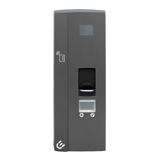
3 Product description The Compleo SOLO advanced charging system described below is suitable for charging electric vehicles indoors and outdoors with installation on a load-bearing wall or a pole. Instructions, states and messages are indicated by means of status LEDs and/or displays. - Page 14 Charging interfaces • HC2 (fixed charging cable with charging plug type 2) • AO2 (socket type 2 with sliding cover) Status displays and/or display • Display • Status LED 3-colour Authentication • RFID tag & RFID card • Giro-E (optional) •...
-
Page 15: Series Label
3.2 Series label There is a serial label on the charging system. The following figure shows the arrangement of information on a serial label: Sample representation The following information can be identified by means of the serial label: Name of the unit manufacturer Address, service number, website of the unit manufacturer Equipment features of the system manufacturer Material number or article number of the system... -
Page 16: Technical Specifications
3.3 Technical specifications General information Compleo SOLO advanced Charging system A01Axxxxxx.xx Article number AV06/ AV19 Equipment (version abbreviation) Charging standard Mode 3/ IEC 61851 Connections Mains connection Terminals Max. connection cross- rigid: 10 mm²; flexible: 6 mm² (with and without ferrule) - Page 17 Charging voltage 400 V/ 3~ Max. charging capacity 11 kW 22 kW Article number A01AExxxxx.11 A01AExxxxx.22 Charging current 16 A/ 3~ 32 A/ 3~ Article number A01AExxxxx.11 A01AExxxxx.22 Charging interface(s) 1 x type 2 charging socket 1 x type 2 charging plug with charging cable Article number A01AE11001.11...
- Page 18 Mechanical data Dimensions (H x W x D) 663 x 253 x 148 mm Housing screwed; polycarbonate (PC); IK 08; DIN EN 61439-(1...7) Protection type IP54 Max. weight 8.0 kg 10.5 kg Article number A01AE11001.11 A01AE11003.11 A01AE12101.11 A01AE11001.22 A01AE11002.11 A01AE11004.11 A01AE12102.11 A01AE11002.22 A01AE12103.11...
- Page 19 1) = Use copper cable only 2) = Circuit breaker must be located in the sub-distribution upstream of the charging system 3) = according to IEC 60898-1, IEC 60947-2 or IEC 61009-1 (deviations possible due to country-specific regulations) 4) = Residual current circuit breaker must be upstream of the charging system 5) = Surge protection must be provided upstream of the charging system, if required 6) = Only when equipped with surge protection device type 1/2/3 - DIN EN 61643-11 2022-11...
-
Page 20: Transport, Packaging And Storage
4 Transport, packaging and storage Transport Inspection Depending on the type and product scope of the charging system, it is delivered either upright or horizontally in appropriate transport and protective packaging. Depending on the type of charging system, air-cushioned protective films and/or cardboard boxes are used. The materials can also be used as underlay during subsequent assembly. -
Page 21: Storage Conditions
4.2 Storage conditions The system should be stored in the same position that it was transported in. If this is not possible for undetermined reasons, it should be stored in the installation position of the charging system. • Ambient temperature for storage: -25 °C to +50 °C •... -
Page 22: Installation
5 Installation Installationsarbeite n Installation work The assembly and installation work requires specific technical qualifications and expertise. There is a danger to life for persons who carry out work for which they have neither been qualified nor instructed. The work may only be carried out by persons who are familiar with it, have been informed about dangers and have the necessary qualifications. - Page 23 ATTENTION Danger from falling charging system If the charging system is installed on a wall structure that does not have sufficient load-bearing capacity, the fastening may tear out and cause the charging system to fall down. Damage to the charging system can be the result. •...
-
Page 24: Notes On Electrical Installation
5.3 Notes on electrical installation DANGER Danger due to electric current Touching live parts will result in electric shock with serious injury or death. • Work on electrical components may only be carried out by a qualified electrician and in accordance with electrical engineering rules. - Page 25 NOTE Fault tripping of the residual current circuit breaker (RCCB) This note only applies to charging systems in which a residual current circuit breaker (RCCB) is installed within the charging system. Under certain installation conditions, it may be necessary to install an additional RCCB in the upstream sub-distribution.
-
Page 26: Unpacking The Charging System
5.4 Unpacking the charging system Tool • TORX-TR20 bit Open the packaging and remove the accessory kit Remove the loading system from the packaging and place it face down on the moulded fibre insert (egg carton) to protect it from scratches. Remove the adhesive safety strip between the connection box and the bottom shell. -
Page 27: Location
Location For professional installation, safe operation and barrier-free access to the charging system, the following points must be observed when selecting the location. • National or local regulations. • Do not install the charging system in the hazard areas of: –... -
Page 28: Mounting On Pillar With Smc Base
100. Fig. 5: Pillar on SMC base 1) = The design and number of supply lines depends on the number and equipment of the compleo Solo charging system to be installed. See chapter 3.3 Technical specifications, page 16. A01Axxxxxx.xx | 04... -
Page 29: Installing The Smc Base
5.6.1 Installing the SMC base Installation requirements • Ground condition with sufficient load-bearing capacity • At least 600 mm free space around the charging system for heat dissipation • Horizontal alignment of the supporting surface • Base filling material (not in scope of delivery) Carrying out installation Dig the excavation pit with the following dimensions:... -
Page 30: Installing The Pillar
5.6.2 Installing the pillar Installation material and tools • 4 screws (M10 x 90, V4A) (accessory kit) • 4 large diameter washers (DIN 9021 10.5 mm, V2A) (accessory kit) • Open-end or ring wrench SW 17 • Torque wrench Fig. 7: Supply line routing Carrying out installation Lay the pillar flat on the ground as close as possible to the installation location. -
Page 31: Installation On Pillar With Asphalt Or Concrete Base Mounting
100. Fig. 9: Pillar with ground mounting 1) = The design and number of supply lines depends on the number and equipment of the compleo Solo charging system to be installed. See chapter 3.3 Technical specifications, page 16. 2022-11... -
Page 32: Inserting The Ground Anchorage
5.7.1 Inserting the ground anchorage NOTE The design of the ground anchorage must be adapted to the subsoil condition and/or special local conditions. The following description of the assembly is therefore only exemplary. Local conditions are not dealt with in detail. Deviating procedures may only be initiated by competent persons. Installation requirements •... - Page 33 Erect the pillar and place it on the selected location. While doing so, carefully pull the supply lines further out of the upper opening to avoid looping. Align the pillar at the selected position. Check that no supply lines are crushed! Mark the hole pattern of the pillar base on the ground.
-
Page 34: Installing The Pillar
5.7.2 Installing the pillar Installation material and tools • - Matching screw connection to selected ground anchorage • 4 large diameter washers (DIN 9021 10.5 mm, V2A) (not in scope of delivery) • Open-end or ring wrench SW 17 • Torque wrench Carrying out installation Place the pillar over the inserted ground... -
Page 35: Mounting The Terminal Box (Single-Sided Pillar)
5.8 Mounting the terminal box (single-sided pillar) Installation material and tools • 5 nuts (M10, V4A) (accessory kit) • 5 large diameter washers (DIN 9021 10.5 mm, V2A) (accessory kit) • Open-end or ring wrench SW 17 • Torque wrench Carrying out installation Push the terminal box onto the 5 threaded bolts of the pillar. -
Page 36: Mounting The Terminal Box (Double-Sided Pillar)
5.9 Mounting the terminal box (double-sided pillar) Installation material and tools • 5 fixing screws (M10 x 60, V4A) (accessory kit) • 5 nuts (M10, V4A) (accessory kit) • 5 large diameter washers (DIN 9021 10.5 mm, V2A) (accessory kit) •... -
Page 37: Installation And Connection
5.10 Installation and connection ATTENTION Damage to the unit Vehicles unintentionally running into the unit can cause damage. • Select the installation site in such a way that damage due to vehicles unintentionally running into the unit is prevented. • If damage cannot be ruled out, suitable protective measures must be taken. - Page 38 Installation material and tools • Drill • Masonry drill Ø 8 mm • 5 wood screws (6 x 60, V2A) (accessory kit) • 5 large diameter washers (DIN 9021 10.5 mm, V2A) (accessory kit) • Wrench WAF 10 • TORX-TR15 bit •...
-
Page 39: External Supply Line
5.10.2 External supply line Push the terminal block into the centre, disengage it from the side and - depending on the upper or lower installation type - turn it into the required position. Then re-engage and push to the end stop. Break the pre-punched cable gland (1) out of the terminal box, deburr and insert the supplied membrane grommets. - Page 40 (M = 1.5 - 1.8 Nm). 1- or 2-phase connection Depending on the local grid structure, the compleo solo charging system can also be operated with 1 or 2 phases. The maximum charging power is reduced analogously to the number of connected phases.
-
Page 41: Equipotential Bonding Conductor
5.10.3 Equipotential bonding conductor Break the pre-punched cable gland out of the terminal box, deburr and insert the supplied membrane grommets. Guide the equipotential bonding cable in the required length through the bushing in the terminal box and secure it with the installed strain relief devices (M = 1.5 Nm). Cable routing from above: Select the cable length up to the lower edge of the terminal box. -
Page 42: Ripple Control Line
5.10.5 Ripple control line Break the pre-punched cable gland out of the terminal box, deburr and insert the supplied membrane grommets. Guide the ripple control line in the required length (max. 30 m) through the bushing in the terminal box and secure it with the installed strain relief devices (M = 1.5 Nm). Cable routing from above: Select the cable length up to the lower edge of the terminal box. -
Page 43: Mounting The Bottom Shell
5.10.7 Mounting the bottom shell Guide the cables to be connected through the openings provided for this purpose in the bottom shell. Hook the lower shell onto the retaining bar of the connection box at an angle of 45° and slowly swing it downwards to the wall support. -
Page 44: Connecting The Internal Supply Line
5.10.8 Connecting the internal supply line Insert the bundled connector of the permanently installed connection line into the terminal block of the power supply line in the terminal box and snap it into place. Fig. 21: Bundled connector Fig. 22: Terminal block A01Axxxxxx.xx | 04 2022-11... -
Page 45: Connecting The Equipotential Bonding
5.10.9 Connecting the equipotential bonding Route the equipotential bonding conductor up to the terminal (1), cut to length and strip the sheath to a length of approx. 70 mm. Strip the wires 18 mm. Connect the line on the external wiring side and ensure that the terminal screws are tightened (M = 2.0 - 4.0 Nm). -
Page 46: Connecting The Ethernet Cable
5.10.10 Connecting the Ethernet cable ATTENTION When connecting the LSA terminals, the minimum cross-section of the individual strands of the network cable must not be less than AWG 26. When using a smaller cross-section than AWG 26, it cannot be guaranteed that a connection can be established. -
Page 47: Connecting The Radio Ripple Control Receiver
5.10.11 Connecting the radio ripple control receiver Route the ripple control line through the intended line channel and fix it with the cable ties supplied. Connect the ripple control line to the terminal (1). Fig. 25: Radio connection Functions with terminal assignment (-> GND) Input 1: 0% charging power Input 2:... -
Page 48: Putting On The Housing Cover
5.10.13 Putting on the housing cover Installation material and tools • 2 TORX screws (4 x 16, V2A) • TORX-TR20 bit • Torque wrench • Profile half cylinder lock (option) Housing cover Retaining screw with countersunk head Place the housing cover on the upper retaining bar of the bottom shell and close it downwards. -
Page 49: 14Attaching The Optional Safety Lock
5.10.14 Attaching the optional safety lock Locking Break out the pre-punched opening in the housing cover and deburr. Insert the key into the lock and turn it until the locking lug is flush with the cylinder. Press the housing cover lightly at the bottom and insert the lock. Turn the key anticlockwise to the "horizontal"... -
Page 50: Commissioning
6 Commissioning DANGER Danger due to electric current Damage to the charging systems or components may expose live parts. Touching live parts will result in electric shock with serious injury or death. • Only operate the charging system when it is undamaged. •... -
Page 51: Testing The Charging System
Testing the charging system The functionality of the installed charging system can be tested either with a vehicle or with a function simulator. With the function simulator it is possible to simulate the functions of an electric vehicle and check the functionality of a charging system or charging point. -
Page 52: Configuration Of The Charging System With Compleo Ducto
6.3 Configuration of the charging system with Compleo DUCTO Compleo DUCTO refers to the software used to manage Compleo charging systems using an end device. Various parameters of the charging system can be set via the configuration interface. The charging system management information is stored on the charging system itself. By specifying the IP of the charging system in the browser of a suitable end device, such as a notebook, a start page is called up and the connection to the charging system is established. - Page 53 Open Properties of <...(TCP/IPv4)>. Enter the IP address from the range 192.168.1.xxx. Note: The IP 192.168.1.100 is assigned for the charging station and must not be used for the configuration of the end device or the computer. The charging system is displayed as a network connection.
-
Page 54: Calling Up The Configuration Interface
6.3.2 Calling up the configuration interface Identify password on DUCTO sticker. Open the local browser and enter the following IP address: https<colon>//192.168.1.100. The DUCTO start page is displayed. 6.3.3 Operator login The start page shows information about the charging status of the charging interfaces. After logging in as an operator, the user can set various parameters such as acoustic and visual signals. -
Page 55: Changing Parameters
6.3.4 Changing parameters Click the desired button. The settings for changeable parameters or other buttons are displayed. Optional: Changing the password Click the <Password> button and follow the instructions. ATTENTION The password cannot be reset to the initial password after the password has been changed. The current password must therefore be kept carefully. - Page 56 The settings for the acoustic signals are displayed. Click the <Off> button. The button is highlighted in red. Confirm selection by clicking on the green button. The blue <Apply changes> button is displayed in the left column of the configuration.
-
Page 57: Log In As Electrician
The <Apply changes> button is displayed in the left column of the configuration. Click the <Apply changes> button and follow the instructions. Perform a restart. The changes are adopted. 6.3.5 Log in as electrician If the "Log in as electrician" checkbox is ticked when entering the password, the instructed electrician can make advanced settings for configuring the charging system: Click <Login>. - Page 58 Confirm qualification. The configuration interface is displayed. Click the topic and follow the instructions. See also "Example: Changing the RCD test cycle" Optional: Changing the password Click the <Password> button and follow the instructions. ATTENTION The password cannot be reset to the initial password after the password has been changed. The current password must therefore be kept carefully.
- Page 59 Click the <Charging station> button. The settings for the parameters of the charging station are displayed. Click the <RCD> button. The settings for the RCD residual current device are displayed. Click the <Test mode> button. 2022-11 A01Axxxxxx.xx | 04...
- Page 60 The settings for the test mode are displayed in the right column of the configuration. Click to open the selection field. The selection options are displayed. Select a new cycle for the test mode. The selected cycle is displayed. Confirm selection by clicking on the green button.
-
Page 61: Ducto Guide
The <Apply changes> button is displayed in the left column of the configuration. Click the <Apply changes> button and follow the instructions. Perform a restart. The changes are adopted. 6.4 DUCTO Guide More information about DUCTO: https://www.compleo- cs.com/fileadmin/user_upload/downloads/solo/Ducto_Guide.pdf 2022-11 A01Axxxxxx.xx | 04... -
Page 62: Operation
Operation Before using the charging system, read the respective documents that are provided with the charging system or that are necessary for operation. This chapter explains the general use of the charging system. The charging processes at the charging systems can be started and stopped by different authorisation methods. Depending on the charging system and product scope, the following forms of operation and authorisation are possible: Free charging: With the "Free charging"... -
Page 63: Charging Process
Charging process The Compleo SOLO charging system is produced in different versions. Depending on the configuration of the charging system, the type of charger interfaces and the procedure for starting a charging process differ. During a charging process, the plug is locked in the vehicle. -
Page 64: Charging The Vehicle
Charging the vehicle 6.3 Configuration of the charging system with Compleo DUCTO, page 52 7.2.1 Authorisation RFID: Hold the RFID card or chip in front of the RFID field. LED lights up "green" when authorisation is successful. Follow the instructions on the display. -
Page 65: Charging Process With Type 2 Plug
7.2.3 Charging process with type 2 plug The display indicates readiness for plugging in: "Type 2 - Please connect vehicle". Insert the charging plug into the vehicle's socket. The display indicates charging process preparation: "Vehicle connected", "Preparing for charging". The display indicates the charging process: "Charging started". -
Page 66: Ending The Charging Process
Ending the charging process 7.3.1 Authorisation RFID: Hold the RFID card or chip in front of the RFID field. LED lights up "green" when authorisation is successful. Follow the instructions on the display. Giro-E: Hold the Girocard in front of the RFID reader. LED lights up "green"... -
Page 67: Ending Charging With Type 2 Plug
7.3.3 Ending charging with type 2 plug The display indicates the end of the charging process: "Type 2 – Charged: XXX – Charging duration: XXX - Ended". The display indicates readiness for plug removal: "Type 2 - Insert plug into charging station to end - charging duration". Pull the charging plug out of the vehicle's socket. -
Page 68: Operating Signals And Displays
Operating Signals and Displays Depending on type and configuration, the charging systems have the ability to output states, processes or errors via a display and/or LEDs. Depending on the type, configuration and the number of charger interfaces of the charging system, the type of representations on the display and/or the colour of the LEDs may differ. - Page 69 Display Message display The charging system indicates the “compleo + hardware: + Firmware + Please wait” state. • The hardware version is displayed. The firmware version is displayed. Initialisation is being prepared. The charging system indicates the "Type 2 - Ready for operation + Please authorise to start"...
- Page 70 The charging system indicates the "Type 2 – Charged: + Charging duration + Charge" state. • The charging process at the corresponding charger interface is in progress. The charged capacity is displayed. The charging duration is displayed. The charging system indicates the "Type 2 – Charged: + Charging duration + Finished"...
- Page 71 The charging system indicates the "Type 2 + Remove a plug" state. • A plug of the corresponding charger interface can be removed. The charging system indicates the "Type 2 + Please connect vehicle" state. • The plug of the corresponding charger interface should be connected to the vehicle.
- Page 72 The charging system indicates the "Type 2 + Finish: Key 3+ Charged + Charging duration + Ending in approx.:" state. • The charging process can be stopped at the corresponding charger interface using key 3. The charged capacity is displayed. The charging duration is displayed. The expected end is displayed.
- Page 73 The charging system indicates the "Type 2 + Code: + Authorisation failed". • The authorisation process has not been successfully completed. The charging process cannot be performed. The charging system indicates the "Type 2 – Finish with entry + Code: + * = Delete + # = Cancel" state. •...
- Page 74 The charging system indicates the "Error during data transfer" state. • An error has occurred during the data transfer of the charging process. A01Axxxxxx.xx | 04 2022-11...
-
Page 75: Charging State Display
7.4.2 Charging state display The following charging state display explains the colour states and the possible colour changes of a charging system with status LEDs: Charging state display: LED colour state LED: The charging system indicates the standby state. "grey" •... -
Page 76: Malfunctions
For charging systems that are not equipped with a display, the start page of the "DUCTO" configuration software must be called up for error detection (see chapter 6.3 Configuration of the charging system with Compleo DUCTO, page 52). The DUCTO start page displays the status of the charging system and possible error codes in the event of a fault. -
Page 77: Error Display And Measures
For charging systems that are not equipped with a display, the start page of the "DUCTO" configuration software must be called up for error detection (see chapter 6.3 Configuration of the charging system with Compleo DUCTO, page 52). The DUCTO start page displays the status of the charging system and possible error codes in the event of a fault. -
Page 78: Groundfailure (B)
9.1.2 GroundFailure (B) Name GroundFailure Area Connector (AC/ DC) Description OCPP1.6: Ground fault circuit interrupter has been activated. The RCD switch, the circuit breaker or the 6mA sensor of the connector has tripped, protective function. Reported by: Station Handling • The error is shown on the display Indication on display Action... -
Page 79: Overvoltage (E)
9.1.5 OverVoltage (E) Name OverVoltage Area Connector (AC) Description OCPP1.6: Voltage has risen above an acceptable level. The voltage of the connector exceeds the permissible value. Reported by: Connector Handling • The error is shown on the display Indication on display Action No action possible by operator. -
Page 80: Readerfailure (H)
9.1.8 ReaderFailure (H) Name ReaderFailure Area Connector (AC/ DC) Description OCPP1.6: Failure with idTag reader. Reported by: Connector Handling • The error is shown on the display Indication on display Action No action possible by operator. Notify customer service. 9.1.9 UnderVoltage (I) Name UnderVoltage... -
Page 81: Isolationwarning (K)
9.1.11 IsolationWarning (K) Name IsolationWarning Area Connector (DC), connector (AC) Description The warning occurs with isolation problems before and during a charging process. Reported by: Connector Handling • The error is shown on the display Indication on display Action No action possible by operator. Notify customer service. 9.1.12 IsolationError (L) Name IsolationError... -
Page 82: Fuseerror (P)
9.1.14 FuseError (P) Name FuseError Area Connector (AC) Description The error occurs when a circuit breaker trips. Reported by: Connector Handling • The error is shown on the display • No new charging process can be started Indication on display Action Have the power path checked by an electrician. -
Page 83: Temperaturesensorlowlimitviolation (S)
9.1.17 TemperatureSensorLowLimitViolation (S) Name TemperatureSensorLowLimitViolation Area Connector Description The error occurs when the temperature sensor delivers values below its valid range. Reported by: Connector Handling • The error is shown on the display • The maximum charging current is lowered Indication on display Action Check the temperature at the location of the charging system. -
Page 84: Rcsensortestrunning (W)
9.1.20 RCSensorTestRunning (W) Name RCSensorTestRunning Area Connector (AC) Description An automatic test of the 6mA sensor is carried out. Reported by: Connector Handling • The message is shown on the display Indication on display Action No action necessary. 9.1.21 DcPsuConnectionFailure (X) Name DcPsuConnectionFailure Area... -
Page 85: Dclnsulationcodefault (Z)
9.1.23 DclnsulationCodeFault (Z) Name DclnsulationCodeFault Area Connector (DC) Description An insulation error has occurred during a DC charging process. Reported by: Connector Handling • The charging process is aborted • The error is shown on the display Indication on display Action Switch the complete charging system off and on again. -
Page 86: Dclnsulationtestfailureoncharge (3)
9.1.26 DclnsulationTestFailureOnCharge (3) Name DclnsulationTestFailureOnCharge Area Connector (DC) Description The insulation test during the charging process has found an error. Reported by: Connector Handling • The charging process is aborted • The error is shown on the display Indication on display Action Switch the complete charging system off and on again. -
Page 87: Samfirmwarecorrupted (6)
9.1.29 samFirmwareCorrupted (6) N)ame samFirmwareCorrupted Area Connector Description The SAM firmware checksum check failed. Reported by: SAMAdapter Handling • The charging process is aborted • The error is shown on the display • No new charging process possible Indication on display Action No action possible by operator. -
Page 88: Saminternalerror (9)
9.1.32 samInternalError (9) Name samInternalError Area Connector Description The SAM reports an internal error. Reported by: SAMAdapter Handling • The charging process is aborted • The error is shown on the display • No new charging process possible Indication on display Action No action possible by operator. -
Page 89: Lpccommunicationerror (C)
9.1.35 LPCCommunicationError (c) Name LPCCommunicationError Area Connector Description Internal error. Reported by: Connector Handling • New charging processes cannot be started • The error is shown on the display Indication on display Action Switch the complete charging system off and on again. Notify customer service if the error persists. -
Page 90: Powermonitoringerror (F)
9.1.38 PowerMonitoringError (f) Name PowerMonitoringError Area Connector Description The charging point controller has detected a mains failure. Reported by: Connector Handling • New charging processes cannot be started • The error is shown on the display Indication on display Action Check the mains supply. -
Page 91: Lpcovervoltageerror (I)
9.1.41 LPCOverVoltageError (i) Name LPCOverVoltageError Area Connector Description The charging point controller has detected an overvoltage. Reported by: Connector Handling • New charging processes cannot be started • The error is shown on the display Indication on display Action Check the mains supply. 9.1.42 LPCHighTemperatureError (j) Name LPCHighTemperatureError... -
Page 92: Maintenance
10 Maintenance Careful and regular maintenance ensures that the functional condition of the charging system is maintained. Only a regularly checked and maintained charging system is able to guarantee maximum availability and reliable charging processes. The maintenance intervals depend on the prevailing operating conditions, such as the frequency of use and environmental influences such as the degree of contamination. -
Page 93: Maintenance Plan
10.1 Maintenance plan Interval Component/location Maintenance work Every 6 Residual current circuit Self-test cycle adjustable via DUCTO (see chapter --- months breaker fehlender Linktext ---, page --- fehlender Linktext ---). Check with simulation device if RCD is not installed in the charging system. -
Page 94: Maintenance And Repair
10.2 Maintenance and repair DANGER Danger due to electric current Damage to the charging systems or components may expose live parts. Touching live parts will result in electric shock with serious injury or death. • Only operate the charging system when it is undamaged. •... -
Page 95: Cleaning
10.3 Cleaning The components inside the charging system need to be cleaned according to the assessment of an expert but this is not always necessary. Any necessary cleaning of the interior must only be carried out after consultation with the operator of the charging system. Cleaning may only be carried out by a properly and professionally instructed person and must never be carried out by a user. -
Page 96: Decommissioning, Dismantling And Disposal
11 Decommissioning, dismantling and disposal The decommissioning and dismantling of the charging system may only be carried out by a qualified electrician. The national legal requirements and regulations must be observed. DANGER Danger due to electric current Touching live parts will result in electric shock with serious injury or death. •... -
Page 97: Disposal Instructions
11.1.1 Disposal instructions The symbol with the crossed-out dustbin indicates that this electrical or electronic appliance must not be disposed of with household waste at the end of its service life. To return the product, contact the manufacturer or dealer. The separate collection of Waste from Electrical and Electronic Equipment (WEEE) is intended to enable the reuse, recycling or other forms of recovery of WEEE and to avoid negative consequences on the environment and human health from the disposal of hazardous substances that may be... -
Page 98: Index
12 Index 1- or 2-phase connection ........40 Handling ..............12 Housing dimensions ........... 100 Abbreviations ............9 Acoustic signals ............. 75 Installation .............. 22 Installation and connection ........ 37 Charging process ..........63 Installation work ............ 22 Charging state display .......... 75 Intended use ............ - Page 99 Index Safety ............... 10 Technical specifications ........16 Safety instructions ..........11 Test ................51 Safety sign.............. 49 Transport ............... 20 Scope of application ..........6 Transport Inspection ........... 20 Series label ............. 15 Signals ..............75 Unpacking .............. 26 SIM ................
-
Page 100: Annexes
Annexes 13 Annexes 13.1 Housing dimensions A01Axxxxxx.xx | 04 2022-11... -
Page 101: Commissioning And Test Report For Ac Charging Systems
Annexes 13.2 Commissioning and test report for AC charging systems Test report for AC charging systems from Compleo Charging Solutions AG 2022-11 A01Axxxxxx.xx | 04... - Page 102 Annexes Test report for AC charging systems from Compleo Charging Solutions AG A01Axxxxxx.xx | 04 2022-11...
- Page 103 Annexes Test report for AC charging systems from Compleo Charging Solutions AG 2022-11 A01Axxxxxx.xx | 04...
- Page 104 Annexes Test report for AC charging systems from Compleo Charging Solutions AG A01Axxxxxx.xx | 04 2022-11...
-
Page 105: Eu Declaration Of Conformity
Annexes 13.3 EU Declaration of Conformity 2022-11 A01Axxxxxx.xx | 04... - Page 106 Annexes A01Axxxxxx.xx | 04 2022-11...
- Page 107 Annexes 2022-11 A01Axxxxxx.xx | 04...
- Page 108 Annexes A01Axxxxxx.xx | 04 2022-11...
- Page 109 Annexes 2022-11 A01Axxxxxx.xx | 04...
- Page 110 Annexes A01Axxxxxx.xx | 04 2022-11...
- Page 111 Annexes Notes 2022-11 A01Axxxxxx.xx | 04...
- Page 112 Annexes © 2022 Compleo. All rights reserved. This document may not be copied in whole or in part without written permission. All illustrations in this document serve as examples only and may differ from the delivered product. All information in this document is subject to change without notice and does not represent a commitment on the part of the manufacturer.
- Page 113 Annexes 2022-11 A01Axxxxxx.xx | 04...
- Page 114 Annexes A01Axxxxxx.xx | 04 2022-11...
Need help?
Do you have a question about the SOLO advanced AV06 and is the answer not in the manual?
Questions and answers