
Related Manuals for Compleo SOLO N+


Summary of Contents for Compleo SOLO N+
- Page 1 Operating instructions Compleo SOLO N+ 40800703/ 40800704 Article number: A15AE1 Issue: 2023_05 Revision: 04...
-
Page 2: Table Of Contents
About this manual ....................5 Scope of application ........................... 6 Further requirements ..........................6 Manufacturer and contact address ......................7 Conventions of presentation ........................7 Abbreviations ............................... 8 Safety ........................9 Warnings ............................... 9 2.1.1 Sectional warnings ..........................9 Intended use .............................. 10 Foreseeable misuse .......................... - Page 3 Commissioning ....................49 Testing the charging system ........................50 System start-up ............................50 Configuration of the charging system with Compleo DUCTO ............51 6.3.1 Creating a network connection ......................51 6.3.2 Calling up the configuration interface .................... 51 DUCTO Guide ............................. 51 Operation ......................
- Page 4 Circuit breaker (MCB) ..........................60 Error display and measures ................61 About this advices ............................. 61 9.1.1 Field of application ..........................61 OCPP 1.6 ..............................61 Compleo-specific .............................63 Maintenance ..................... 67 10.1 Maintenance plan ............................68 10.1.1 Automatic RCD test ..........................68 10.2 Maintenance and repair ...........................69...
-
Page 5: About This Manual
In addition to the instructions in this manual, the local accident prevention regulations and the national industrial safety regulations apply. Illustrations are for basic understanding and may differ from the actual design of the charging system. More information about the product: https//www.compleo-cs.com/service/installation-service. 2023_05 A15AE1 | 04... -
Page 6: Scope Of Application
About this manual Scope of application This manual is valid for the following article numbers of the charging system Compleo SOLO N+: neoom international Compleo Charging Solutions Ausstattung 40800703 i00019539 A15AE11003.22 40800704 i00019540 A15AE12103.11 Further requirements The operator must ensure that the charging system is properly installed and used as intended. -
Page 7: Manufacturer And Contact Address
About this manual Manufacturer and contact address Compleo Charging Solutions AG Oberste-Wilms-Straße 15a 44309 Dortmund, Germany Tel.: +49 231 534 923 - 777 Fax: +49 231 534 923 - 790 e-mail address: info@compleo-cs.com Conventions of presentation For easy and quick understanding, different information in this manual is presented or highlighted as follows: •... -
Page 8: Abbreviations
About this manual Abbreviations Abbreviation Explanation Alternating Current Direct Current Electromagnetic Compatibility EVSEID Electric Vehicle Supply Equipment ID Human-Machine Interface Identification Number Infrared Kilowatt hour Liquid Crystal Display Charging system/charging station Miniature Circuit Breaker MessEG Measuring and calibration law MessEV Measuring and calibration regulations Not Available/Applicable OCPP... -
Page 9: Safety
Safety 2 Safety In order to ensure operational safety of the charging equipment and to avoid serious injuries caused by flashovers or short circuits, the following information and safety instructions for operating the unit must be observed. Repair work on the unit must only be carried out by authorised specialist personnel. The housing of the unit may only be opened by persons who have been properly instructed. -
Page 10: Intended Use
Safety Intended use The charging system is intended exclusively for charging electric vehicles. The charging system is suitable for public and semi-public areas and can be used indoors and outdoors. The charging system is intended exclusively for stationary installation. Any use beyond this is considered improper use. The manufacturer is not liable for damages resulting from this. -
Page 11: Personnel Qualification
Safety Personnel qualification Qualified and trained electricians meet the following requirements: • Knowledge of general and special safety and accident prevention regulations. • Knowledge of the relevant electrical engineering regulations. • Product-specific knowledge through appropriate training. • Ability to identify hazards associated with electricity. DANGER Danger due to electric current Touching live parts will result in electric shock with serious injury or death. -
Page 12: Dangers And Residual Risks
Dangers and residual risks NOTE Compleo charging systems as a whole do not contain SVHCs (Substances of Very High Concern) in a concentration of more than 0.1 % (w/w), related to the individual charging station. However, individual components may contain SVHCs in concentrations > 0.1 % (w/w). -
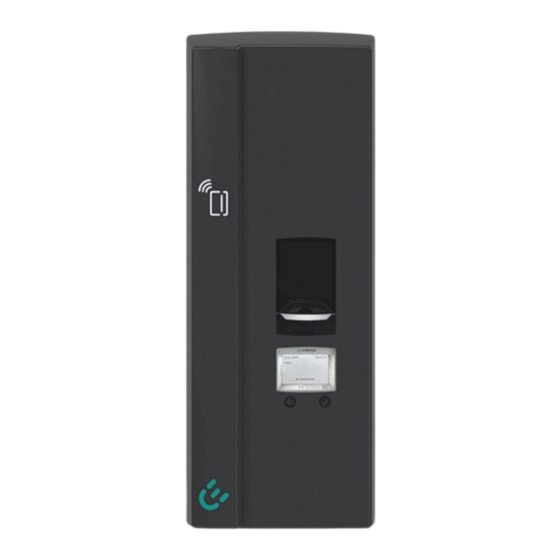
Page 13: Product Description
Product description 3 Product description The Compleo SOLO N+ charging system described below is suitable for charging electric vehicles indoors and outdoors with installation on a load-bearing wall or a pole. Instructions, states and messages are indicated by means of status LEDs and/or displays. - Page 14 Product description Charging interfaces • HC2 (fixed charging cable with charging plug type 2) • AO2 (socket type 2 with sliding cover) Status display • Status LED 3-colour Authentication • RFID tag & RFID card • Giro-E (optional) • Remote authorisation (optional) Surge protection (optional) •...
-
Page 15: Series Label
Product description 3.2 Series label There is a serial label on the charging system. The following figure shows the arrangement of information on a serial label: Sample representation The following information can be identified by means of the serial label: Name of the unit manufacturer Address, service number, website of the unit manufacturer System designation of the system manufacturer... -
Page 16: Technical Specifications
Product description 3.3 Technical specifications General information Compleo SOLO N+ Charging system 40800703/ 40800704 Article number A15AE1xxxxxx.xx Equipment (version abbreviation) Charging standard Mode 3/ IEC 61851 Connections Mains connection Terminals Max. connection cross- rigid: 10 mm²; flexible: 6 mm² (with and without ferrule) section Max. - Page 17 Product description Electrical characteristics Mains voltage 230 V/ 400 V Max. rated current 16 A 32 A Article number 40800704 i00019540 40800703 i00019539 Mains frequency 50 Hz Network form TT/ TN Protection class Overvoltage category Charging voltage 400 V/ 3~ Max.
- Page 18 Product description Ambient conditions Ambient temperature -25 °C to +40 °C Operating temperature (∅ 24 ≤ 35 °C Storage temperature -25 °C to +50 °C Relative humidity ≤ 95 % (non-condensing) Altitude ≤ 2000 m above sea level Mechanical data Dimensions (H x W x D) 663 x 253 x 148 mm Housing...
- Page 19 Product description Legal regulations 2014/53/EU (Radio Equipment Directive) 2011/65/EU (RoHS Directive) 2001/95/EG (Directive on General Product Safety) 2012/19/EU (WEEE Directive) (EU) 2019/1021 (EU-POP Ordinance) (EU) 1907/2006 (REACH Regulation) SVHC EU no. CAS no. Lead (Pb) 231-100-4 7439-92-1 4,4'-isopropylidenediphenol 201-245-8 80-05-7 (bisphenol A;...
-
Page 20: Transport, Packaging And Storage
Transport, packaging and storage 4 Transport, packaging and storage Transport Inspection Depending on the type and product scope of the charging system, it is delivered either upright or horizontally in appropriate transport and protective packaging. Depending on the type of charging system, air-cushioned protective films and/or cardboard boxes are used. -
Page 21: Storage Conditions
Transport, packaging and storage 4.2 Storage conditions The system should be stored in the same position that it was transported in. If this is not possible for undetermined reasons, it should be stored in the installation position of the charging system. •... -
Page 22: Installation
Installation 5 Installation Installationsarbeite n Installation work The assembly and installation work requires specific technical qualifications and expertise. There is a danger to life for persons who carry out work for which they have neither been qualified nor instructed. The work may only be carried out by persons who are familiar with it, have been informed about dangers and have the necessary qualifications. - Page 23 Installation ATTENTION Danger from falling charging system If the charging system is installed on a wall structure that does not have sufficient load-bearing capacity, the fastening may tear out and cause the charging system to fall down. Damage to the charging system can be the result.
-
Page 24: Notes On Electrical Installation
Installation 5.3 Notes on electrical installation DANGER Danger due to electric current Touching live parts will result in electric shock with serious injury or death. • Work on electrical components may only be carried out by a qualified electrician and in accordance with electrical engineering rules. - Page 25 Installation ATTENTION Unit fault Installing an additional RCCB protection device can cause irritation during the automatic self-test for charging systems with built-in RCCB. Faults and unit failure can be the result. • If an additional RCCB is required due to installation conditions, the additional RCCB must be selective to the built-in RCCB.
-
Page 26: Unpacking The Charging System
Installation 5.4 Unpacking the charging system Tool • TORX-TR20 bit Open the packaging and remove the accessory kit Remove the loading system from the packaging and place it face down on the moulded fibre insert (egg carton) to protect it from scratches. Remove the adhesive safety strip between the connection box and the bottom shell. -
Page 27: Location
Installation Location For professional installation, safe operation and barrier-free access to the charging system, the following points must be observed when selecting the location. • National or local regulations. • Do not install the charging system in the hazard areas of: –... -
Page 28: Mounting On Pillar With Smc Base
76. Fig. 5: Pillar on SMC base 1) = The design and number of supply lines depends on the number and equipment of the compleo Solo charging system to be installed. See chapter 3.3 Technical specifications, page 16. A15AE1 | 04... -
Page 29: Installing The Smc Base
Installation 5.6.1 Installing the SMC base Installation requirements • Ground condition with sufficient load-bearing capacity • At least 600 mm free space around the charging system for heat dissipation • Horizontal alignment of the supporting surface • Base filling material (not in scope of delivery) Carrying out installation Dig the excavation pit with the following dimensions:... -
Page 30: Installing The Pillar
Installation 5.6.2 Installing the pillar Installation material and tools • 4 screws (M10 x 90, V4A) (accessory kit) • 4 large diameter washers (DIN 9021 10.5 mm, V2A) (accessory kit) • Open-end or ring wrench SW 17 • Torque wrench Fig. -
Page 31: Installation On Pillar With Asphalt Or Concrete Base Mounting
76. Fig. 9: Pillar with ground mounting 1) = The design and number of supply lines depends on the number and equipment of the compleo Solo charging system to be installed. See chapter 3.3 Technical specifications, page 16. 2023_05... -
Page 32: Inserting The Ground Anchorage
Installation 5.7.1 Inserting the ground anchorage NOTE The design of the ground anchorage must be adapted to the subsoil condition and/or special local conditions. The following description of the assembly is therefore only exemplary. Local conditions are not dealt with in detail. Deviating procedures may only be initiated by competent persons. Installation requirements •... - Page 33 Installation Erect the pillar and place it on the selected location. While doing so, carefully pull the supply lines further out of the upper opening to avoid looping. Align the pillar at the selected position. Check that no supply lines are crushed! Mark the hole pattern of the pillar base on the ground.
-
Page 34: Installing The Pillar
Installation 5.7.2 Installing the pillar Installation material and tools • - Matching screw connection to selected ground anchorage • 4 large diameter washers (DIN 9021 10.5 mm, V2A) (not in scope of delivery) • Open-end or ring wrench SW 17 •... -
Page 35: Mounting The Terminal Box (Single-Sided Pillar)
Installation 5.8 Mounting the terminal box (single-sided pillar) Installation material and tools • 5 nuts (M10, V4A) (accessory kit) • 5 large diameter washers (DIN 9021 10.5 mm, V2A) (accessory kit) • Open-end or ring wrench SW 17 • Torque wrench Carrying out installation Push the terminal box onto the 5 threaded bolts of the pillar. - Page 36 Installation A15AE1 | 04 2023_05...
-
Page 37: Mounting The Terminal Box (Double-Sided Pillar)
Installation 5.9 Mounting the terminal box (double-sided pillar) Installation material and tools • 5 fixing screws (M10 x 60, V4A) (accessory kit) • 5 nuts (M10, V4A) (accessory kit) • 5 large diameter washers (DIN 9021 10.5 mm, V2A) (accessory kit) •... -
Page 38: Installation And Connection
Installation 5.10 Installation and connection ATTENTION Damage to the unit Vehicles unintentionally running into the unit can cause damage. • Select the installation site in such a way that damage due to vehicles unintentionally running into the unit is prevented. •... - Page 39 Installation Installation material and tools • Drill • Masonry drill Ø 8 mm • 5 wood screws (6 x 60, V2A) (accessory kit) • 5 large diameter washers (DIN 9021 10.5 mm, V2A) (accessory kit) • Wrench WAF 10 • TORX-TR15 bit •...
-
Page 40: External Supply Line
Installation 5.10.2 External supply line Push the terminal block into the centre, disengage it from the side and - depending on the upper or lower installation type - turn it into the required position. Then re-engage and push to the end stop. Break the pre-punched cable gland (1) out of the terminal box, deburr and insert the supplied membrane grommets. - Page 41 (M = 1.5 - 1.8 Nm). 1- or 2-phase connection Depending on the local grid structure, the compleo solo charging system can also be operated with 1 or 2 phases. The maximum charging power is reduced analogously to the number of connected phases.
-
Page 42: Data Line
Installation 5.10.3 Data line Break the pre-punched cable gland out of the terminal box, deburr and insert the supplied membrane grommets. Guide the data line in the required length (max. 30 m) through the bushing in the terminal box and secure it with the installed strain relief devices (M = 1.5 Nm). Cable routing from above: Select the cable length up to the lower edge of the connection box + 15 mm. -
Page 43: Mounting The Bottom Shell
Installation 5.10.6 Mounting the bottom shell Guide the cables to be connected through the openings provided for this purpose in the bottom shell. Hook the lower shell onto the retaining bar of the connection box at an angle of 45° and slowly swing it downwards to the wall support. -
Page 44: Connecting The Internal Supply Line
Installation 5.10.7 Connecting the internal supply line Insert the bundled connector of the permanently installed connection line into the terminal block of the power supply line in the terminal box and snap it into place. Fig. 21: Bundled connector Fig. 22: Terminal block A15AE1 | 04 2023_05... -
Page 45: Connecting The Ethernet Cable
Installation 5.10.8 Connecting the Ethernet cable ATTENTION When connecting the LSA terminals, the minimum cross-section of the individual strands of the network cable must not be less than AWG 26. When using a smaller cross-section than AWG 26, it cannot be guaranteed that a connection can be established. -
Page 46: Connecting The Radio Ripple Control Receiver
Installation 5.10.9 Connecting the radio ripple control receiver Route the ripple control line through the intended line channel and fix it with the cable ties supplied. Connect the ripple control line to the terminal (1). Fig. 24: Radio connection Functions with terminal assignment (-> GND) Input 1: 0% charging power Input 2:... -
Page 47: Putting On The Housing Cover
Installation 5.10.11 Putting on the housing cover Installation material and tools • 2 TORX screws (4 x 16, V2A) • TORX-TR20 bit • Torque wrench • Profile half cylinder lock (option) Housing cover Retaining screw with countersunk head Place the housing cover on the upper retaining bar of the bottom shell and close it downwards. -
Page 48: Attaching The Optional Safety Lock
Installation 5.10.12 Attaching the optional safety lock Locking Break out the pre-punched opening in the housing cover and deburr. Insert the key into the lock and turn it until the locking lug is flush with the cylinder. Press the housing cover lightly at the bottom and insert the lock. Turn the key anticlockwise to the "horizontal"... -
Page 49: Commissioning
Commissioning 6 Commissioning DANGER Danger due to electric current Damage to the charging systems or components may expose live parts. Touching live parts will result in electric shock with serious injury or death. • Only operate the charging system when it is undamaged. •... -
Page 50: Testing The Charging System
Commissioning Testing the charging system The functionality of the installed charging system can be tested either with a vehicle or with a function simulator. With the function simulator it is possible to simulate the functions of an electric vehicle and check the functionality of a charging system or charging point. -
Page 51: Configuration Of The Charging System With Compleo Ducto
Commissioning 6.3 Configuration of the charging system with Compleo DUCTO Compleo DUCTO refers to the software used to manage Compleo charging systems using an end device. Various parameters of the charging system can be set via the configuration interface. The charging system management information is stored on the charging system itself. By specifying the IP of the charging system in the browser of a suitable end device, such as a notebook, a start page is called up and the connection to the charging system is established. -
Page 52: Operation
Operation Operation Before using the charging system, read the respective documents that are provided with the charging system or that are necessary for operation. This chapter explains the general use of the charging system. The charging processes at the charging systems can be started and stopped by different authorisation methods. -
Page 53: Charging Process
Operation Charging process The Compleo SOLO charging system is produced in different versions. Depending on the configuration of the charging system, the type of charger interfaces and the procedure for starting a charging process differ. During a charging process, the plug is locked in the vehicle. -
Page 54: Charging The Vehicle
Operation Charging the vehicle 6.3 Configuration of the charging system with Compleo DUCTO, page 51 7.2.1 Authorisation RFID: Hold the RFID card or chip in front of the RFID field. LED lights up "green" when authorisation is successful. Follow the instructions on the display. - Page 55 Operation 2023_05 A15AE1 | 04...
-
Page 56: Ending The Charging Process
Operation Ending the charging process 7.3.1 Authorisation RFID: Hold the RFID card or chip in front of the RFID field. LED lights up "green" when authorisation is successful. Follow the instructions on the display. Remote authorisation: The display indicates the charging process: "Type 2 –... -
Page 57: Ending Charging With Type 2 Plug
Operation 7.3.3 Ending charging with type 2 plug LED changes from "blue" to "green". • The charging process has ended. LED "green": • Ready for plug removal. Pull the charging plug out of the vehicle's socket. The charging system changes to the standby state. •... -
Page 58: Charging State Display
Operation Operating Signals and Displays 7.4.1 Charging state display The following charging state display explains the colour states and the possible colour changes of a charging system with status LEDs: Charging state display: LED colour state LED: The charging system indicates the standby state. "grey"... -
Page 59: Acoustic Signals
Operation 7.4.2 Acoustic signals In the following table the possible acoustic signals are listed and explained: Acoustic signals 1 x short Sounds when the RFID card is presented and indicates "Card read". This signal requires user interaction: • - Present card for authorisation 2 x short •... -
Page 60: Malfunctions
Malfunctions 8 Malfunctions Residual current circuit breaker (RCCB) In the event of a residual current, the residual current circuit breaker trips and the charging system is switched off. To switch on again, proceed as follows: Eliminate the cause of the error. Activate the residual current circuit breaker by pushing up the locking slide on the side of the housing. -
Page 61: Error Display And Measures
Error display and measures 9 Error display and measures The charging system displays an error code on the display in case of errors. If several errors occur at the same time or in combination, the respective error codes are shown one after the other on the display. - Page 62 Error display and measures UnderVoltage The voltage has dropped below an acceptable level. Inspection by qualified electrician required. Error when locking or unlocking the plug. It must be checked ConnectorLockFailure - whether the plug is connected correctly. OverCurrentFailure The vehicle has drawn more current than specified for an extended period of time.
-
Page 63: Compleo-Specific
Error display and measures 9.3 Compleo-specific Title Code Troubleshooting advice IsolationWarning Insulation problems occurred before or during a charging process. Inspection by qualified electrician required. IsolationError Insulation problems occurred before or during a charging process. Inspection by qualified electrician required. - Page 64 Error display and measures samTransactionMemoryFull SAM has no more free memory for new charging processes. SAM must be replaced by an authorized electrician. samEVSEIDMemoryFull SAM has no more free memory for new configuration parameters. SAM must be replaced by an authorized electrician.
- Page 65 Error display and measures ShortCircuitError The charge point controller has detected a short circuit between CP and PE. Inspection by qualified electrician required. LPCOverVoltageError The charge point controller has detected an overvoltage. Inspection by qualified electrician required. LPCHighTemperatureError The charging point controller has detected a temperature that is too high.
- Page 66 Error display and measures AutomaticRcdResetSuccess The cause of the failed test of the RCD has been eliminated. No action required. The socket could not be opened. Inspection by qualified OutletOpenError electrician required. RCSensorErrorDuringCharge The 6mA sensor has tripped during a charging process. Inspection by qualified electrician required if the error occurs frequently.
-
Page 67: Maintenance
Maintenance 10 Maintenance Careful and regular maintenance ensures that the functional condition of the charging system is maintained. Only a regularly checked and maintained charging system is able to guarantee maximum availability and reliable charging processes. The maintenance intervals depend on the prevailing operating conditions, such as the frequency of use and environmental influences such as the degree of contamination. -
Page 68: Maintenance Plan
Maintenance 10.1 Maintenance plan Interval Component/location Maintenance work Every 6 Residual current circuit Self-test cycle adjustable via DUCTO (see chapter --- months breaker fehlender Linktext ---, page --- fehlender Linktext ---). Check with simulation device if RCD is not installed in the charging system. -
Page 69: Maintenance And Repair
Maintenance 10.2 Maintenance and repair DANGER Danger due to electric current Damage to the charging systems or components may expose live parts. Touching live parts will result in electric shock with serious injury or death. • Only operate the charging system when it is undamaged. •... -
Page 70: Cleaning
Maintenance 10.3 Cleaning The components inside the charging system need to be cleaned according to the assessment of an expert but this is not always necessary. Any necessary cleaning of the interior must only be carried out after consultation with the operator of the charging system. Cleaning may only be carried out by a properly and professionally instructed person and must never be carried out by a user. -
Page 71: Decommissioning, Dismantling And Disposal
Decommissioning, dismantling and disposal 11 Decommissioning, dismantling and disposal The decommissioning and dismantling of the charging system may only be carried out by a qualified electrician. The national legal requirements and regulations must be observed. DANGER Danger due to electric current Touching live parts will result in electric shock with serious injury or death. -
Page 72: Disposal Instructions
Decommissioning, dismantling and disposal 11.1.1 Disposal instructions The symbol with the crossed-out dustbin indicates that this electrical or electronic appliance must not be disposed of with household waste at the end of its service life. To return the product, contact the manufacturer or dealer. -
Page 73: Memory And Display Module Sam
Memory and display module SAM 12 Memory and display module SAM The charging system is equipped with a permanently installed memory and display module (SAM). Charging systems with a built-in memory and display module (SAM) are subject to the weights and measures law. -
Page 74: Index
Index 13 Index 1- or 2-phase connection ........41 Installation .............. 22 Installation and connection ....... 38 Abbreviations ............8 Installation work ............ 22 Acoustic signals ............ 59 Intended use ............10 Internal supply line ..........44 Charging process ..........53 Charging state display ......... - Page 75 Index SAM ................73 Test ................. 50 SAM® ..............81 Transport ............... 20 Scope of application ..........6 Transport Inspection ........... 20 Series label ............. 15 Signals ..............59 Unpacking .............. 26 SIM ................46 User ................10 Storage ..............20 Storage conditions ..........
-
Page 76: Annexes
Annexes 14 Annexes 14.1 Housing dimensions A15AE1 | 04 2023_05... -
Page 77: Commissioning And Test Report For Ac Charging Systems
Annexes 14.2 Commissioning and test report for AC charging systems 2023_05 A15AE1 | 04... - Page 78 Annexes A15AE1 | 04 2023_05...
- Page 79 Annexes 2023_05 A15AE1 | 04...
- Page 80 Annexes A15AE1 | 04 2023_05...
-
Page 81: Memory And Display Module Sam
Annexes 14.3 Memory and display module SAM® Fig. 30:Title page - memory and display module (SAM) (exemplary) 2023_05 A15AE1 | 04... - Page 82 Annexes Notes A15AE1 | 04 2023_05...
- Page 83 Operating instructions Article number: SAM_EN Issue: 2023-06 Revision: 04...
- Page 84 About this manual....................3 SAM product description ..................5 Product information ..........................5 Intended use ............................6 Controls and display ..........................6 Type and rating plates ..........................7 Overview of all displays (examples) ......................8 SAM system overview ........................... 12 Integration of the subsystem in a charging column ................
-
Page 85: About This Manual
These instructions reflect the state-of-the-art of the product at the time of publication. The contents of these instructions are not the subject of a contract, but are for information purposes. Compleo Charging Solutions AG reserves the right to make changes to the content and technical specifications of these instructions without having to disclose them. - Page 86 Abbreviations Abbreviation Explanation Alternating Current Delivery point Plug designation for: Combined Charging System Abbreviation for plug designation: CHAdeMO Charge Point Operator Cyclic Redundancy Check Direct Current Electromagnetic Compatibility EVSEID Electric Vehicle Supply Equipment Human-Machine Interface Hardware Identification Number Infrared Kilowatt hour Liquid Crystal Display Charging device controller LIEF...
-
Page 87: Sam Product Description
SAM product description SAM is the memory and display module that permanently stores the start and final meter reading of the charging processes and displays them on request. Angaben z um Pr odukt Product information SAM, in combination with a verified meter, fulfils the possible requirements of the local calibration law when charging an electric vehicle at a charging station. -
Page 88: Intended Use
Intended use The SAM is used to collect, store, display and verify meter reading and customer identification data for charging points in charging stations for electric vehicles. One SAM is used per charging point. The SAM is a measuring capsule and consists of the display storage module and an electronic energy meter. -
Page 89: Type And Rating Plates
Typens child Type and rating plates The SAM type plate and meter rating plate are listed below. Typically, the SAM type plate is visible from the outside (view of the charging station) and the meter rating plate is not. Type plate of the SAM Lower field Figure 2: Type plate of the SAM (example) Display frame:... -
Page 90: Overview Of All Displays (Examples)
Overview of all displays (examples) Info screens (without interaction with the user) Boot screen Ready for operation (idle state) 2 second progress bar (from left to right) until the Display of the ID after a successful authorisation. timing starts. Current measured values. The number of arrow After a few seconds, the last digits of the ID are symbols represent the number of loaded phases. - Page 91 Interactive screen displays with the user to invoke charging procedures. After entering the start value, press "Next" to enter the final value. After entering the final value, press "Check". (Called up after touching one of the two buttons). If there are several data sets (possible with a charge Screen output for a found entry.
- Page 92 Possible error screens Error message: there is a communication or memory Error message: there is an internal fault in the SAM. problem. Error message: no entry was found. Error message: the data set found is inconsistent. Billing is only possible with a data set that complies The data set does not comply with calibration law with calibration law! and is therefore cannot be billed!
- Page 93 Explanation of the display positions Text displays during boot screen after switching on and restarting the SAM. SAM S/N Serial number of the SAM Meter S/N Serial number of the meter Placeholder Firmware version Checksum Firmware checksum Production date Day of manufacture (day of programming) Charging Number of charging processes that are still possible and can be saved.
-
Page 94: Sam System Overview
SAM system overview The SAM forms a unit with the associated meter, which is used to record and store measured values. The following image shows the functional arrangement of the SAM (green) in a charging station. VEHICLE BATTERY Current Charging equipment Current Current + meter... -
Page 95: Integration Of The Subsystem In A Charging Column
Integration of the subsystem in a charging column With the subsystem, it is possible to carry out all measurements and data collection. The following illustrations show the required connections between the components within a charging column. AC system SAM incl. Charging system PSU 12 VDC Display &... -
Page 96: Communication Connections
Communication connections The SAM is equipped with the following non-reactive communication interfaces: • IR interface: Point-to-point connection to the electricity meter • 20 mA interface: Point-to-point connection to the charging system control unit (LES) • HMI interface (2 buttons and display) for interaction with the user Connection to the electricity meter The memory and display module is connected to the electricity meter via a secure connection. - Page 97 The flash memory is used for the firmware (without update function). The RTC is used for the calendar, time and stopwatch function. Additional flash memory The additional and non-volatile long-term memory is used for storing charging processes and can be read out by the control unit.
-
Page 98: Time Measurement Of The Charging Service Duration (Stopwatch Function)
2.11 Time measurement of the charging service duration (stopwatch function) The SAM has an internal quartz-controlled real time clock (RTC). This is used for time measurement (for the charging time or standing time). The charging service time is the time between the moment the charging equipment detects the connection of a vehicle and the moment the charging equipment detects the disconnection of the vehicle from the charging equipment. - Page 99 Checking the time measurement by means of the data interface The time measurement accurate to a millisecond can be read out from the SAM via the available 20 mA interface using the SML protocol. Checking the time measurement in the manufacturing process In each SAM, a connection pin is available which signals the start and stop time by means of a signal change (flank-controlled).
- Page 100 The following diagram illustrates the check procedure. Stopwatch ( external Check B/ D module reference) Start a simulated charging process After receiving the start signal, Control unit (module B) or test Start time measurement after the PIN is toggled (flank) and stand (moduleD) sends start receiving the flank signal from the internal stopwatch starts...
- Page 101 System overview of electricity meter The meter is an approved meter under calibration law and is used to measure the amount of energy delivered to the delivery point. The following picture shows the meter with its functional components. Bidirectional data interface (D0); Bidirectional data interface (D0);...
-
Page 102: Charging Process With Sam
Charging process with SAM This chapter explains in more detail the displays that are shown in the SAM during a charging process. For information on how to charge at a charging station, please refer to the operating instructions for the respective charging station. -
Page 103: Two Seconds Until Charging
Two seconds until charging As soon as a vehicle and the charging column are connected and the authorisation was successful, a black two- second progress bar (from left to right) is shown in the display. Figure 12: Two-second progress bar (example) Charging process After this time has elapsed, the display changes to the next representation and the time measurement begins. -
Page 104: End Of The Charging Process
End of the charging process After the charging process is completed (after disconnection from the vehicle on the charging station side), the information is shown on the display for checking purposes. The display can be extended by a further 20 seconds by pressing the right key and it closes automatically after this period has elapsed. -
Page 105: Query Previous Charging Processes With Sam
Query previous charging processes with SAM Query via backend Using OCPP, individual or all stored data sets can be retrieved from the backend via the charging equipment control unit. Query on site Within the scope of saving all charging processes, the same can be called up after entering the start and final values of the meter readings of a specific charging process. - Page 106 Entering the final value The final value of the same charging process is entered in the same way. Selecting the "Check" option outputs the desired information. Figure 16: Entering the final value (example) Display of the stored data If the actual values are entered correctly, the information will be as shown in the illustration below. The display can be closed with the right key, but it also closes itself after an appropriate time window.
- Page 107 Information screens In certain situations, information screens are displayed if technical problems occur during a charging process. The following information screens are displayed if either a power failure or the communication between the SAM and the control unit was interrupted during a charging process. Then the word "Invalid" is shown in the display under Duration.
- Page 108 Error screens Permanent error states in charging equipment cannot be excluded either. The following error screens are possible and are explained here. Figure 21: Limited operation (example) "Limited operation" occurs when • energy measurements are no longer possible. (e.g. meter is not working correctly). Consequence: The charging point goes to "Out of service".
- Page 109 Figure 23: Entry not found (example) An entry in the data memory cannot be found if • the two start and end meter readings entered are not found in the data set (Tubel). The operator has either entered incorrect values or has entered the data at an incorrect charging point (SAM).
- Page 110 Lock screen The following picture shows the lock screen. Figure 24: Lock screen (example) This screen appears if five incorrect entries took place while entering readings to retrieve historical data. This function is intended to prevent misuse. 2023_06 SAM_EN | 01...
-
Page 111: Technical Data
Technical data Unless otherwise stated, the technical specifications are the same for all unit types. Measuring capsule Ambient conditions Specification Value Unit Internal spaces or Approved installation site at least IP34 protected area Temperature range -25 - +70 °C Humidity ≤... -
Page 112: Sam Installation
(230 VAC). Connection (6-pole) for 12 V and 20 mA interface Figure25: Top: Front and rear with AC meter, below the representation of the connections; left AC, right DC 1) = not relevant for compleo Solo 2023_06 SAM_EN | 01... -
Page 113: Connection Of Sam And Meter
Connection of SAM and meter Please observe the following safety instructions before connecting the unit. Specifications for the electrical connection • The supply line must be hard-wired into the existing installation and comply with the nationally applicable legal requirements. • The rated current I must be selected to match the back-up fuse and the circuit breaker. - Page 114 Connection of the meter to the supply network Figure27: Connection diagrams for meter; left AC, right DC Please refer to the charging station manufacturer's documentation for information on how the connection is made within a charging station. 2023_06 SAM_EN | 01...
- Page 115 Notes 2023_06 SAM_EN | 01...
- Page 116 Annexes © 2023 Compleo. All rights reserved. This document may not be copied in whole or in part without written permission. All illustrations in this document serve as examples only and may differ from the delivered product. All information in this document is subject to change without notice and does not represent a commitment on the part of the manufacturer.
Need help?
Do you have a question about the SOLO N+ and is the answer not in the manual?
Questions and answers