
Subscribe to Our Youtube Channel
Related Manuals for Compleo Cito BM 500


Summary of Contents for Compleo Cito BM 500
- Page 1 Operating instructions Cito BM 500 Compleo Charging Solutions AG Oberste-Wilms-Str. 15a D-44309 Dortmund www.compleo-cs.com Revision: 02 | 2022-05...
-
Page 2: Table Of Contents
About this manual....................4 Further requirements ..........................4 Manufacturer and contact address ......................5 Conventions of presentation ........................5 Abbreviations ............................6 Safety ........................8 Warnings ..............................8 2.1.1 Sectional warnings ..........................9 2.1.2 Embedded warnings .......................... 9 Intended use ............................9 Foreseeable misuse .......................... - Page 3 5.5.3 Data connection cable ........................47 5.5.4 RJ45 connector ..........................49 Installation of the cable management system (CMS) and the collision protection ......51 5.6.1 BM installation..........................52 5.6.2 Inserting the ground anchorage ...................... 52 5.6.3 Installation with concrete base ....................... 54 Commissioning......................
-
Page 4: About This Manual
Illustrations are for basic understanding and may differ from the actual design of the charging system. Further requirements A warranty with regard to function and safety is only given if this manual is observed. Compleo Charging Solutions AG is not liable for personal injury or damage to property caused by failure to observe the operating instructions. -
Page 5: Manufacturer And Contact Address
About this manual Manufacturer and contact address Compleo Charging Solutions AG Oberste-Wilms-Straße 15a 44309 Dortmund, Germany Tel.: +49 231 534 923 - 777 Fax: +49 231 534 923 - 790 e-mail address: info@compleo-cs.com Conventions of presentation For easy and quick understanding, different information in this manual is presented or highlighted as follows: •... -
Page 6: Abbreviations
About this manual Abbreviations Abbreviation Explanation Alternating Current (en: Alternating Current) Delivery point Combined Charging System (de: kombiniertes Ladesystem) Abbreviation for plug designation: CHAdeMO Charge Point Operator (en: Charge Point Operator) Cyclic Redundancy Check (en: Cyclic Redundancy Check) Direct Current (en: Direct Current) Electromagnetic Compatibility... - Page 7 About this manual Abbreviation Explanation Miniature Circuit Breaker MessEG Measuring and calibration law MessEV Measuring and calibration regulations MSB/MDL Metering point operators/ metering service providers MSP/ EMSP (Electric) Mobility Service Provider OCPP Open Charge Point Protocol Power Supply Unit (en: Power Supply Unit) Residual Current Device Real-Time Clock...
-
Page 8: Safety
Safety Safety In order to ensure operational safety of the charging equipment and to avoid serious injuries caused by flashovers or short circuits, the following information and safety instructions for operating the unit must be observed. Repair work on the unit must only be carried out by authorised specialist personnel. The housing of the unit may only be opened by persons who have been properly instructed. -
Page 9: Sectional Warnings
Safety 2.1.1 Sectional warnings Sectional warnings refer to entire chapters, a section or several paragraphs within this manual. Sectional warnings are presented as follows (example warning): WARNING Type and source of the danger. Possible consequences if the danger is not observed. •... -
Page 10: Personnel Qualification
Dangers and residual risks NOTE Compleo charging systems as a whole do not contain SVHCs (Substances of Very High Concern) in a concentration of more than 0.1 % (w/w), related to the individual charging station. However, individual components may contain SVHCs in concentrations > 0.1 % (w/w). - Page 11 Safety WARNING Risk of electric shock and fire due to the use of adapters! Using adapters on the charging cable can cause serious injury and damage to property. • Do not use any adapters on the charging cable! 2022-05 D111F311X1 | 02...
-
Page 12: Product Description
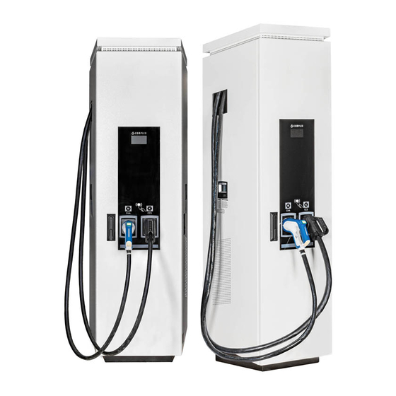
Product description Product description The charging system described below is designed for charging electric vehicles indoors and outdoors with installation on solid ground. Design Cover (roof) Air outlet Colour display Counter DC (compliant with calibration law) Status display of the charger interfaces Door with locking mechanism Near field illumination Basic housing... -
Page 13: Series Label
Product description Series label The charging systems from Compleo Charging Solutions AG can be identified by an individual serial number. A series label is attached inside the charging system. The following illustration shows an example of a series label: Fig. 2: Series label... -
Page 14: Scope Of Delivery
In addition to the charging station, the scope of delivery of the charging system includes the components listed on the following page. The illustration shows a fully equipped compleo® Cito BM 500 charging system. Due to special requirements and/or customer wishes, a purchased charging system of the same type may differ from this illustration. - Page 15 Product description The scope of delivery of the compleo® Cito BM 500 includes the following features and components: Charger interfaces (optional depending on version) • C2 (smooth cable CCS) • CH (smooth cable CHAdeMO) • AO2 (socket outlet with sliding cover type 2)
-
Page 16: General Functions And Scope Of Application
General Functions and Scope of Application The compleo® Cito BM 500 charging system has the functionality for mode 3 and mode 4 charging. It is produced in different versions. The one-piece housing can be mounted on solid ground using two mounting methods. -
Page 17: Technical Specifications
Product description Technical specifications The following table is an excerpt from the standard portfolio of Compleo Charging Solutions charging systems. A purchased charging system may deviate from this list according to customer-specific wishes and requirements. If changes have been made to a standard product, the modified charging system is identified with a separate table of technical specifications in the Annex. -
Page 18: Dc Charger Interface
Product description 3.6.1 1 x DC charger interface General information Charging system Cito BM 500 Charging mode acc. to IEC 61851/ mode 3 + mode 4 DC charger interface 1 x CCS plug with attached cable 1 x CHAdeMO plug with attached cable... - Page 19 Product description Protective devices 1 x C100A, 1 x B16A Ambient conditions Ambient temperature -25 °C to +40 °C Operating temperature (∅ 24 h) ≤ 35 °C Storage temperature -25 °C to +50 °C Relative humidity ≤ 95 % (non-condensing) Altitude ≤...
- Page 20 Product description Communication interfaces Data communication TCP/IP Data connection Backend communication OCPP 1.5, OCPP 1.6 RFID standard Multireader (frequency/ transmission (13.56 MHz/ 13.9 mW,11.4 dBm) (125 kHz; 134.2 kHz/ 26 mW, 14.1 dBm) power) Certification and standards Low Voltage Directive 2014/35/EU EMV Directive 2014/30/EU...
-
Page 21: Dc Charger Interfaces
Product description 3.6.2 2 x DC charger interfaces General information Charging system Cito BM 500 Charging mode Mode 3/ IEC 61851 DC charger interfaces 1 x CCS plug with attached cable 1 x CHAdeMO plug with attached cable Connections Mains connection... - Page 22 Product description Protective devices 1 x C100A 1 x B16A Ambient conditions Ambient temperature -25 °C to +40 °C Operating temperature (∅ 24 h) ≤ 35 °C Storage temperature -25 °C to +50 °C Relative humidity ≤ 95 % (non-condensing) Altitude ≤...
- Page 23 Product description Communication interfaces Data communication TCP/IP Data connection Backend communication OCPP 1.5, OCPP 1.6 RFID standard Multireader (frequency/ transmission (13.56 MHz/ 13.9 mW,11.4 dBm) (125 kHz; 134.2 kHz/ 26 mW, 14.1 dBm) power) Certification and standards Low Voltage Directive 2014/35/EU EMV Directive 2014/30/EU...
-
Page 24: Dc Charger Interface And 1 X Ac Charger Interface (2 In 1)
Product description 3.6.3 1 x DC charger interface and 1 x AC charger interface (2 in 1) General information Charging system Cito BM 500 Charging mode Mode 3/ IEC 61851 DC charger interface: 1 x CCS plug with attached cable... - Page 25 Product description Electrical characteristics Mains frequency 50 Hz Network form TT/ TN Protection class Rated short-time withstand (400 V AC) 6 kA current (I Overvoltage category Max. pre-fuse 125 A gG/gL Protective devices RCCB: 40 A/0,03 A, type A; RDC-DD: 6 mA 1 x C100A, 1 x B16A;...
- Page 26 Product description Communication interfaces Data communication TCP/IP Data connection Backend communication OCPP 1.5, OCPP 1.6 RFID standard Multireader (frequency/ transmission (13.56 MHz/ 13.9 mW,11.4 dBm) (125 kHz; 134.2 kHz/ 26 mW, 14.1 dBm) power) Certification and standards Low Voltage Directive 2014/35/EU EMV Directive 2014/30/EU...
-
Page 27: Dc Charger Interfaces And 1 X Ac Charger Interface (3 In 1)
Product description 3.6.4 2 x DC charger interfaces and 1 x AC charger interface (3 in 1) General information Charging system Cito BM 500 Charging mode Mode 3/ IEC 61851 DC charger interface: 1 x CCS plug with attached cable,... - Page 28 Product description Electrical characteristics Mains frequency 50 Hz Network form TT/ TN Protection class Rated short-time withstand (400 V AC) 6 kA current (I Overvoltage category Max. pre-fuse 125 A gG/gL Protective devices RCCB: 40 A/0,03 A, type A; RDC-DD: 6 mA 1 x C100A, 1 x B16A Ambient conditions...
- Page 29 Product description Communication interfaces Data communication TCP/IP Data connection Backend communication OCPP 1.5, OCPP 1.6 RFID standard Multireader (frequency/ transmission (13.56 MHz/ 13.9 mW,11.4 dBm) (125 kHz; 134.2 kHz/ 26 mW, 14.1 dBm) power) Certification and standards Low Voltage Directive 2014/35/EU EMV Directive 2014/30/EU...
-
Page 30: Transport, Packaging And Storage
Transport, packaging and storage Transport, packaging and storage Transport Inspection Depending on the type and product scope of the charging system, it is delivered either upright or horizontally in appropriate transport and protective packaging. Depending on the type of charging system, air-cushioned protective films and/or cardboard boxes are used. -
Page 31: Transport With Lifting Gear
Transport, packaging and storage Transport with lifting gear WARNING Suspended loads Falling loads can cause serious injury or death. • Never step under suspended loads. • Attach slings only to the designated attachment points. • Only use approved lifting gear and slings in perfect condition with sufficient load capacity. •... - Page 32 Transport, packaging and storage Put the roof back on and screw it on. Insert the cover. Screw the cover back on. Close and lock the left side door of the charging station (2) and screw the screw back in (1). Step 14 is to be applied analogously for the right door Close and lock the door of the charging...
-
Page 33: Installation
Installation Installation Incorrect installation can lead to personal injury and damage to property. It must be ensured that the assembly and electrical installation are carried out professionally and that the local protective measures and the specifications of the energy supplier are observed. The charging systems may therefore only be installed by a qualified electrician and persons who are demonstrably qualified. -
Page 34: Parking Space Arrangement
Installation Parking space arrangement For the simplest and most convenient execution of individual or parallel charging processes, a well thought-out arrangement of the parking spaces around the charging system is recommended. The principle of the parking space arrangement is shown in the following illustrations. 3 charging points Connection to AC interface: •... -
Page 35: Installation Work
Installation Installationsarbeite n Installation work The assembly and installation work requires specific technical qualifications and expertise. There is a danger to life for persons who carry out work for which they have neither been qualified nor instructed. The work may only be carried out by persons who are familiar with it, have been informed about dangers and have the necessary qualifications. -
Page 36: Installation Version Bm
Installation 5.4.1 Installation version BM Installation sequence Select a suitable location. Check parts and installation material for completeness. Check the substrate. Route the power supply cable. Drill mounting holes. Insert screw anchors. Place and align the charging system. Insert the power supply cable into the charging system. Fasten the charging system with installation material. - Page 37 Installation Carrying out installation Mark boreholes. Drill boreholes according to instructions. Fill boreholes up to a height of 55 mm with injection mortar. Insert screw anchor with internal thread (M 10) and an external diameter of 16 mm. Allow the injection mortar to harden. Fig.
- Page 38 Installation If the supply lines cannot be routed through the bottom of the charging system, they can be fed in at the rear (A), right (B) or left (C) of the unit base. Holes can be drilled in the area on the corresponding sides of the unit base using a suitable tool.
- Page 39 Installation NOTE To protect the charging system, we recommend to install an approach limiter (e.g. bollard). 2022-05 D111F311X1 | 02...
-
Page 40: Installation Bm With Concrete Base
Installation 5.4.2 Installation BM with concrete base Installation sequence Select a suitable location. Check parts and installation material for completeness. Dig the excavation pit. Check the substrate. Route the power supply cable. Compact and level the ground. Place and align the concrete base. Insert the power supply cable into the concrete base. - Page 41 Fill the last 300 mm inside the concrete base with concrete base filling material. – ½ sack of filling material (Compleo) – The use of the filling material is mandatory as it reduces the penetration of moisture into the charging system from the ground.
-
Page 42: Base Plate
Installation 5.4.3 Base plate A base plate is installed inside the charging system. The base plate serves among other things as strain relief. NOTE The base plate must be mounted. Otherwise the operation of the charging system may be limited. Fig. -
Page 43: Closing The Housing
Installation 5.4.4 Closing the housing A swing lever mechanism is installed in the front door of the housing. Depending on the version, this is a single or double lock. A lock can be installed inside the swivel lever to prevent access by unauthorised persons. Fig. -
Page 44: Electrical Installation
Installation Electrical installation DANGER Danger due to electric current Touching live parts will result in electric shock with serious injury or death. • Work on electrical components may only be carried out by a qualified electrician and in accordance with electrical engineering rules. •... -
Page 45: Power Supply Cable
Installation 5.5.1 Power supply cable Internal Wiring Cut the power supply cable to length so that the cables above the base plate have a length of approx. 300 mm. Strip 30 mm of insulation from the individual wires or according to the cable lugs to be used. Connect all conductors of the power supply cable to the external wiring side as shown in the adjacent figure. - Page 46 Installation NOTE For electrical installation, the applicable standards for surge protection must be observed. We recommend the use of a type 1+2 surge arrester for charging stations with public mains connection in the pre-counter area. Charging stations which are supplied from distribution boards that are already protected must be equipped with at least one type 2 surge arrester.
-
Page 47: Data Connection Cable
Installation 5.5.3 Data connection cable If it is necessary to connect an individual charging station to a network by means of a cable, this must be done using a pre-installed cable connector. The cable connector is prepared on the system side and must be connected on the mains side during electrical installation. - Page 48 Installation White plastic cap Connect the individual wires of the cable as shown in the adjacent figure. Cut the wires with an electric cutter flush with the housing. Screw the connecting piece to the cable connector. – How far the connecting piece has to be screwed onto the cable connector depends on the diameter of the network cable used on the network...
-
Page 49: Rj45 Connector
Installation 5.5.4 RJ45 connector If a connection to a network by means of an internally installed switch is required (depending on the equipment), this is to be realised using an RJ45 connector. The connector is enclosed and must be connected during electrical installation. - Page 50 Installation – The distance between the beginning of the wound braided shield and the wire manager must not exceed 15 mm. Cut off the wires protruding from the wire manager with an electric cutter so that the ends are flush. The protrusion must not exceed 0.5 mm.
-
Page 51: Installation Of The Cable Management System (Cms) And The Collision Protection
Installation Installation of the cable management system (CMS) and the collision protection Arrangement charging station DC parking space AC parking space Charging plug range (6 m radius) Fig. 30: CMS arrangement • - Ground mounting; the CMS is anchored to the ground with a mounting plate. -
Page 52: Bm Installation
Installation 5.6.1 BM installation The installation site must be chosen so that the cables do not protrude onto the road and do not come to rest between the kerb and the road. Installation sequence Select a suitable installation site. Check ground for stability. Check parts and installation material for completeness. - Page 53 Installation Mark the hole pattern of the base plate on the ground. Move the CMS to the side so that the markings on the ground are accessible. Drill holes on the markings using a suitable drilling tool. – Drill hole diameter: according to the manufacturer's specification of the ground anchor –...
-
Page 54: Installation With Concrete Base
Installation 5.6.3 Installation with concrete base The installation site must be chosen so that the cables do not protrude onto the road and do not come to rest between the kerb and the road. Installation sequence Check parts and installation material for completeness. Dig the pit. - Page 55 Installation Carrying out installation Dig the excavation pit. – Width: 1311 mm – Length: 2135 mm – Depth: 800 mm Prepare the substrate for a stable installation of the CMS. – Fill the excavation pit by 100 mm with chippings (1). –...
- Page 56 Installation Carefully place CMS (1) on a suitable surface. Release carabiner (2). Fig. 33: Preparing the CMS Set up CMS (1) vertically. Insert pipe from CMS into concrete base (2). Fig. 34: Inserting the CMS Mount the positioning aid (2). Fill the excavation pit by 100 mm with excavated material (1).
- Page 57 Installation Tighten fastening screws, see arrows. Align the pipes of the CMS vertically using a spirit level. Compress the filling material. Front view Side view Fig. 36: Fastening the CMS Fill the excavation pit with 300 mm of excavated material. Align the pipes of the CMS vertically again using a spirit level.
-
Page 58: Commissioning
Commissioning Commissioning Commissioning must be carried out by a qualified electrician or by a person trained and instructed in electrical matters. The effectiveness of the protective measures and the correct mechanical and electrical installation must be checked by a qualified electrician. Commissioning may only be carried out when all necessary internal covers are fitted and the housing is completely closed. -
Page 59: Testing The Charging System
Commissioning Testing the charging system The functionality of the installed charging system can be tested either with a vehicle or with a function simulator. With the function simulator it is possible to simulate the functions of an electric vehicle and check the functionality of a charging system or charging point. -
Page 60: Operation
Operation Operation Before using the charging system, read the respective documents that are provided with the charging system or that are necessary for operation. This chapter explains the general use of the charging system. The charging processes at the charging systems can be started and stopped by different authorisation methods. -
Page 61: Charging Process
Operation Charging process The compleo® Cito BM 500 charging system is produced in different versions. Depending on the configuration of the charging system, the type and number of charger interfaces and the procedure for starting a charging process differ. The fully equipped "3 in 1" charging system includes three charger interfaces. Depending on the product scope, the number and type of charger interfaces differ from this number and configuration. -
Page 62: Connection Versions
Operation Connection versions Overview of connection versions Charger interface Version Operating method AC-1 RFID AC-2 Giro-E AC-3 Remote authorisation Type 2 socket DC-1 RFID DC-2 Giro-E DC-3 Remote authorisation CSS plug DC-4 RFID DC-5 Giro-E DC-6 Remote authorisation CHAdeMO plug Illustrations similar In the event of an error during the charging process, this is indicated via the display and via the status LED: Error display:... -
Page 63: Version Ac-1
Operation 7.2.1 Version AC-1 RFID | type 2 socket The following brief instructions are intended for use with a charging system with RFID authorisation, display, status LED and sliding socket and the AC charger interface. Illustration similar Start charging process: The display indicates readiness for charging: "Type 2 - Ready for operation - Please authorise to start". - Page 64 Operation RFID | type 2 socket Illustration similar End charging process: The display indicates readiness for charging: "Type 2 – Charged: XXX – Charging duration: XXX – Charge". Hold the RFID card or chip used previously in front of the RFID field. The display indicates the end of the charging process: "Type 2 –...
-
Page 65: Version Ac-2
Operation 7.2.2 Version AC-2 Giro-E | type 2 socket The following brief instructions are intended for use with a charging system with Giro-E authorisation, display, status LED and sliding socket and the AC charger interface. Illustration similar Start charging process: The display indicates readiness for charging: "Type 2 - Ready for operation - Please authorise to start". - Page 66 Operation Giro-E | type 2 socket Illustration similar End charging process: The display indicates the charging process: "Type 2 – Charged: XXX – Charging duration: XXX – Charge". Hold the Giro card (in Germany) in front of the RFID field. The display indicates the end of the charging process: "Type 2 –...
-
Page 67: Version Ac-3
Operation 7.2.3 Version AC-3 Remote authorisation | Type 2 socket The following brief instructions are intended for use with a charging system with remote authorisation, display, status LED and sliding socket and the AC charger interface. Illustration similar Start charging process: Download and install app for smartphone or tablet or start web interface. - Page 68 Operation Remote authorisation | Type 2 socket Illustration similar End charging process: The display indicates the charging process: "Type 2 – Charged: XXX – Charging duration: XXX – Charge". Follow the instructions of the app or web interface for finishing the charging process.
-
Page 69: Version Dc-1
Operation 7.2.4 Version DC-1 RFID | CCS plug The following brief instructions are intended for use with a charging system with RFID authorisation, display, status LED and attached CCS cable for the DC charger interface. Illustration similar Start charging process: The display indicates readiness for charging: "CCS –... - Page 70 Operation RFID | CCS plug Illustration similar End charging process: The display indicates readiness for charging: "CCS – Charged: XXX – Charging duration: XXX – Charge". Hold the RFID card or chip used previously in front of the RFID field. The display indicates the end of the charging process: "CCS –...
-
Page 71: Version Dc-2
Operation 7.2.5 Version DC-2 Giro-E | CCS plug The following brief instructions are intended for use with a charging system with Giro-E authorisation, display, status LED and attached CCS cable for the DC charger interface. Illustration similar Start charging process: The display indicates readiness for charging: "CCS –... - Page 72 Operation Giro-E | CCS plug Illustration similar End charging process: The display indicates the charging process: "CCS – Charged: XXX – Charging duration: XXX – Charge". Hold the Giro card (in Germany) in front of the RFID field. The display indicates the end of the charging process: "CCS –...
-
Page 73: Version Dc-3
Operation 7.2.6 Version DC-3 Remote authorisation | CCS plug The following brief instructions are intended for use with a charging system with remote authorisation, display, status LED and attached CCS cable for the DC charger interface. Illustration similar Start charging process: Download and install app for smartphone or tablet or start web interface. - Page 74 Operation Remote authorisation | CCS plug Illustration similar End charging process: The display indicates the charging process: "CCS – Charged: XXX – Charging duration: XXX – Charge". Follow the instructions of the app or web interface for finishing the charging process. The display indicates the end of the charging process: "CCS –...
-
Page 75: Version Dc-4
Operation 7.2.7 Version DC-4 RFID | CHAdeMO plug The following brief instructions are intended for use with a charging system with RFID authorisation, display, status LED and attached CHAdeMO cable for the DC charger interface. Illustration similar Start charging process: The display indicates readiness for charging: "CHAdeMO –... - Page 76 Operation RFID | CHAdeMO plug Illustration similar End charging process: The display indicates readiness for charging: "CHAdeMO – Charged: XXX – Charging duration: XXX – Finished in approx: XXX". Hold the RFID card or chip used previously in front of the RFID field. The display indicates the end of the charging process: "CHAdeMO –...
-
Page 77: Version Dc-5
Operation 7.2.8 Version DC-5 Giro-E | CHAdeMO plug The following brief instructions are intended for use with a charging system with Giro-E authorisation, display, status LED and attached CHAdeMO cable for the DC charger interface. Illustration similar Start charging process: The display indicates readiness for charging: "CHAdeMO –... - Page 78 Operation Giro-E | CHAdeMO plug Illustration similar End charging process: The display indicates the charging process: "CHAdeMO – Charged: XXX – Charging duration: XXX – Charge". Hold the Giro card (in Germany) in front of the RFID field. The display indicates the end of the charging process: "CHAdeMO –...
-
Page 79: Version Dc-6
Operation 7.2.9 Version DC-6 Remote authorisation | CHAdeMO plug The following brief instructions are intended for use with a charging system with remote authorisation, display, status LED and attached CCS cable for the DC charger interface. Illustration similar Start charging process: Download and install app for smartphone or tablet or start web interface. - Page 80 Operation Remote authorisation | CHAdeMO plug Illustration similar End charging process: The display indicates the charging process: "CHAdeMO – Charged: XXX – Charging duration: XXX – Charge". Follow the instructions of the app or web interface for finishing the charging process. The display indicates the end of the charging process: "CHAdeMO –...
-
Page 81: Operating Signals And Displays
7.3.1 Message display The following message display explains the displays for the left side of a charging system with display: Message display The charging system indicates the “compleo + hardware: + Firmware + Please wait” state. • The hardware version is displayed. The firmware version is displayed. - Page 82 Operation The charging system indicates the "CCS - CHA - Type 2 + Remove a plug" state. • A plug of any charger interface can be removed. The charging system indicates the "Please connect vehicle" state. • The plug of the corresponding charger interface should be connected to the vehicle.
- Page 83 Operation The charging system indicates the "CHA - Plug the plug in the charging station to end + Charging duration:" state. • The charging process can be stopped at the corresponding charger interface. The plug must be plugged into the charging station. The charging duration is displayed.
- Page 84 Operation The charging system indicates the "Type 2 – Charged: + Charging duration + Have a good trip" state. • The charging process at the corresponding charger interface is in progress. The charged capacity is displayed. The charging duration is displayed. Have a good trip. The charging system indicates the "CCS –...
- Page 85 Operation The charging system indicates the "CHA – Charged: + Charging duration + Have a good trip" state. • The charging process at the corresponding charger interface is in progress. The charged capacity is displayed. The charging duration is displayed. Have a good trip. The charging system indicates the "CCS + Remove a plug"...
- Page 86 Operation The charging system indicates the "Disconnect plug from vehicle to end" state. • The charging process can be stopped at the corresponding charger interface. The plug must be disconnected from the vehicle. The charging system indicates the "CCS + Starting a new charging process not possible!"...
- Page 87 Operation The charging system indicates the "CCS + Please connect vehicle" state. • The plug of the corresponding charger interface should be connected to the vehicle. The charging system indicates the "CHA + Please connect vehicle" state. • The plug of the corresponding charger interface should be connected to the vehicle.
- Page 88 Operation The charging system indicates the "Type 2 - Plug the plug in the charging station" state. • The plug of the corresponding charger interface must be plugged into the charging station. The charging system indicates the "CCS - Ready for operation + Please use card or key 1 to start"...
- Page 89 Operation The charging system indicates the "Type 2 + AN: + TAN: * = Delete + # = Cancel" state. • The charger interface is ready for operation. A charging process can be started. A request number is required. A transaction number is required.
- Page 90 Operation The charging system indicates the "CCS + Finish: Key 1+ Charged + Charging duration + Ending in approx.:" state. • The charging process can be stopped at the corresponding charger interface using key 1. The charged capacity is displayed. The charging duration is displayed.
- Page 91 Operation The charging system indicates the "CHA + Charged: + Charging duration: + Isolation warning" state. • The charging process at the corresponding charger interface is in progress. The charged capacity is displayed. The charging duration is displayed. An isolation warning is displayed. The charging system indicates the "Type 2 + Charged: + Charging duration: + Isolation warning"...
- Page 92 Operation The charging system indicates the "Type 2: + Charging process cancelled + Status code:" state. • The charging process has been cancelled at the corresponding charger interface. A status code is displayed. The charging system indicates the "CCS - Please authorise with card or press key 1"...
- Page 93 Operation The charging system indicates the "CCS + Code: "Authorisation in progress – Please wait" state. • Authorisation is in progress. The charger interface is prepared for a charging process. The charging system indicates the "CHA + Code: "Authorisation in progress –...
- Page 94 Operation The charging system indicates the "Type 2 – Finish with entry + Code: + * = Delete + # = Cancel" state. • The charging process at the corresponding charger interface is in progress. The charging process can be finished by entering the code.
- Page 95 Operation 105 The charging system indicates the "CCS - Initialisation + Please wait” state. • The charging process is being initialised and will start soon. 106 The charging system indicates the "CHA - Initialisation + Please wait” state. • The charging process is being initialised and will start soon. 107 The charging system indicates the "Type 2 - Initialisation + Please wait”...
-
Page 96: Charging State Display
Operation 7.3.2 Charging state display The following charging state display explains the colour states and the possible colour changes of a charging system with status LEDs: Charging state display: LED colour state LED: The charging system indicates the standby state. "grey"... -
Page 97: Maintenance
Maintenance Maintenance Careful and regular maintenance ensures that the functional condition of the charging system is maintained. Only a regularly checked and maintained charging system is able to guarantee maximum availability and reliable charging processes. The maintenance intervals depend on the prevailing operating conditions, such as the frequency of use and environmental influences such as the degree of contamination. -
Page 98: Maintenance Plan
Maintenance Maintenance plan Interval Component/location Maintenance work Every 6 Residual current circuit Check with test button. months breaker Surge arrester Visual inspection or check with test button. Yearly Location Visual inspection, e.g. for distances to objects (bushes, electrical installations ,etc.), attachment. Electrical components Visual inspection, e.g. -
Page 99: Maintenance Work
Maintenance Maintenance work 8.2.1 Replacing the filter mat at the air outlet Open the door of the charging station. Unscrew the screw on the filter holder (1). Tilt down the filter clamping plate (2) and replace the filter mat. Fold up the filter clamping plate again and screw it tight. -
Page 100: Cleaning
Maintenance Cleaning The components inside the charging system need to be cleaned according to the assessment of an expert but this is not always necessary. Any necessary cleaning of the interior must only be carried out after consultation with the operator of the charging system. Cleaning may only be carried out by a properly and professionally instructed person and must never be carried out by a user. -
Page 101: Decommissioning, Dismantling And Disposal
Decommissioning, dismantling and disposal Decommissioning, dismantling and disposal The decommissioning and dismantling of the charging system may only be carried out by a qualified electrician. The national legal requirements and regulations must be observed. DANGER Danger due to electric current Touching live parts will result in electric shock with serious injury or death. -
Page 102: Index
Index 10 Index Air outlet ............99 Abbreviations ............6 Functions .............. 16 Acoustic signals ............ 96 Handling ............... 10 Base plate ............. 42 Installation ............33 Cable management system Installation version Description ............16 BM ..............36 Installation ..........51, 52, 54 Installation work .......... - Page 103 Index System start-up ............ 59 Transport Inspection ..........30 Technical specifications ........17 User ................ 9 Test ............... 59 Transport .............. 30 Warnings ..............8 2022-05 D111F311X1 | 02...
-
Page 104: Annexes
Annexes 11 Annexes Declaration of conformity: Declaration of conformity of the compleo® Cito BM 500 charging system D111F311X1 | 02 2022-05... - Page 105 Annexes Base design: Design drawing of the concrete base of the Cito BM 500 2022-05 D111F311X1 | 02...
Need help?
Do you have a question about the Cito BM 500 and is the answer not in the manual?
Questions and answers