
Subscribe to Our Youtube Channel
Related Manuals for Compleo ADVANCED IMS bm SAM


Summary of Contents for Compleo ADVANCED IMS bm SAM
- Page 1 Operating instructions Compleo ADVANCED IMS bm SAM® Compleo DUO IMS SAM®/ DUO fleet IMS SAM® Article number: A11XCXXXXX Issue: 2023-02 Revision: 02...
-
Page 2: Table Of Contents
About this manual ....................4 Further requirements ..........................4 Manufacturer and contact address ......................5 Conventions of presentation ........................5 Abbreviations ............................... 6 Safety ........................7 Warnings ............................... 7 2.1.1 Sectional warnings ..........................8 Intended use ..............................8 Foreseeable misuse ............................ 8 Safety instructions for the user ........................ - Page 3 System start-up ............................36 Configuration of the charging system with Compleo DUCTO............38 6.3.1 Creating a network connection ......................38 6.3.2 Calling up the configuration interface ................... 40 6.3.3 Operator login ............................. 40 6.3.4 Changing parameters ......................... 41 6.3.5 Log in as electrician ........................... 43 Operation ......................
-
Page 4: About This Manual
Illustrations are for basic understanding and may differ from the actual design of the charging system. Further requirements A warranty with regard to function and safety is only given if this manual is observed. Compleo Charging Solutions AG is not liable for personal injury or damage to property caused by failure to observe the operating instructions. -
Page 5: Manufacturer And Contact Address
Manufacturer and contact address Compleo Charging Solutions AG Oberste-Wilms-Straße 15a 44309 Dortmund, Germany Tel.: +49 231 534 923 - 777 Fax: +49 231 534 923 - 790 e-mail address: info@compleo-cs.com Conventions of presentation For easy and quick understanding, different information in this manual is presented or highlighted as follows: •... -
Page 6: Abbreviations
Abbreviations Abbreviation Explanation Alternating Current Direct Current Electromagnetic Compatibility EVSEID Electric Vehicle Supply Equipment ID Human-Machine Interface Identification Number Infrared Kilowatt hour Liquid Crystal Display Charging system/charging station Miniature Circuit Breaker MessEG Measuring and calibration law MessEV Measuring and calibration regulations Not Available/Applicable OCPP Open Charge Point Protocol... -
Page 7: Safety
2 Safety In order to ensure operational safety of the charging equipment and to avoid serious injuries caused by flashovers or short circuits, the following information and safety instructions for operating the unit must be observed. Repair work on the unit must only be carried out by authorised specialist personnel. The housing of the unit may only be opened by persons who have been properly instructed. -
Page 8: Sectional Warnings
2.1.1 Sectional warnings Sectional warnings refer to entire chapters, a section or several paragraphs within this manual. Sectional warnings are presented as follows (example warning): WARNING Type and source of the danger. Possible consequences if the danger is not observed. •... -
Page 9: Personnel Qualification
Personnel qualification Qualified and trained electricians meet the following requirements: • Knowledge of general and special safety and accident prevention regulations. • Knowledge of the relevant electrical engineering regulations. • Product-specific knowledge through appropriate training. • Ability to identify hazards associated with electricity. DANGER Danger due to electric current Touching live parts will result in electric shock with serious injury or death. -
Page 10: Dangers And Residual Risks
Dangers and residual risks NOTE Compleo charging systems as a whole do not contain SVHCs (Substances of Very High Concern) in a concentration of more than 0.1 % (w/w), related to the individual charging station. However, individual components may contain SVHCs in concentrations > 0.1 % (w/w). -
Page 11: Product Description
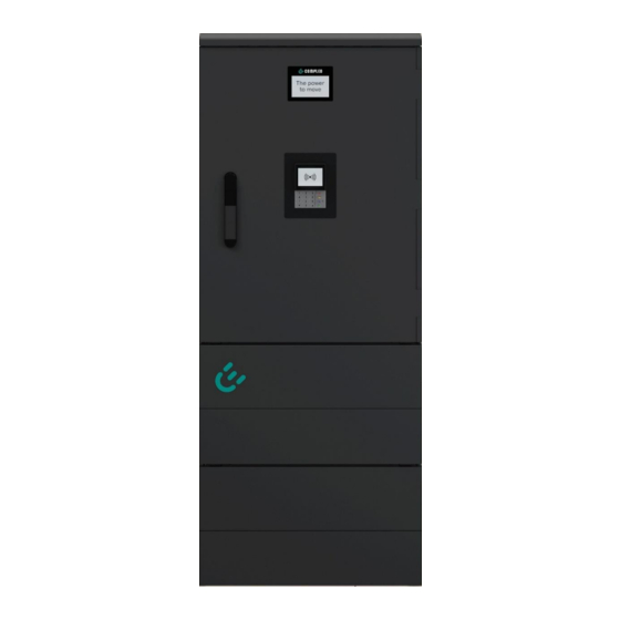
3 Product description The charging system described below is suitable for charging electric vehicles indoors and outdoors with installation on solid ground. The operation of the charging system is designed to give clear and easily understandable instructions, statuses and messages, which can be indicated to the user by means of status LEDs and displays. Design Cover (roof) SAM display and storage module... -
Page 12: Scope Of Delivery
Scope of delivery The scope of delivery of the Compleo DUO IMS SAM®/ Compleo DUO fleet IMS SAM® (Compleo ADVANCED IMS SAM®) includes, in addition to the charging column, the following features and components: Authentication • Credit card terminal (payment with credit card, charging current or website) •... - Page 13 Documentation: Circuit diagram Operating instructions including design drawings Installation accessories (optional): Base filler Installation material (optional) (optional) Surge protection (optional): Surge arrester (optional) 2023-02 A11XCXXXXX | 02...
-
Page 14: Series Label
3.3 Series label The charging systems from Compleo Charging Solutions AG can be identified by an individual serial number. A series label is attached inside the charging system. The following illustration shows an example of a series label: Illustration similar... -
Page 15: Technical Specifications
3.4 Technical specifications The following table is an excerpt from the standard portfolio of Compleo Charging Solutions AG charging systems. A purchased charging system may deviate from this list according to customer-specific wishes and requirements. If changes have been made to a standard product, the modified charging system is identified with a separate table of technical specifications in the Annex. - Page 16 RCCB: 40 A/0.03 A, type A; RCCB: 40 A/0.03 A, type B RDC-DD: 6 mA 2 x C20A, 2 x C40A, 1 x B10A 1 x B10A A11XCXXXXX | 02 2023-02...
- Page 17 Ambient conditions Ambient temperature -25 °C to +40 °C Operating temperature (∅ 24 ≤ 35 °C Storage temperature -25 °C to +50 °C Relative humidity ≤ 95 % (non-condensing) Altitude ≤ 2000 m above sea level Mechanical data Dimensions (H x W x D) BM: 1483 x 590 x 330 (H x W x D) Max.
- Page 18 Legal regulations 2014/53/EU (Radio Equipment Directive) 2011/65/EU (RoHS Directive) 2001/95/EG (Directive on General Product Safety) 2012/19/EU (WEEE Directive) (EU) 2019/1021 (EU-POP Ordinance) (EU) 1907/2006 (REACH Regulation) SVHC EU no. CAS no. Lead (Pb) 231-100-4 7439-92-1 4,4'-isopropylidenediphenol 201-245-8 80-05-7 (bisphenol A; BPA) A11XCXXXXX | 02 2023-02...
-
Page 19: General Functions And Scope Of Application
RBG LED. The meter reading of a charging point can be quickly captured and read from an appropriately recessed window on the housing. Depending on the product class and scope, the charging systems are suitable for use in public and semi-public areas. In general, all charging systems from Compleo Charging Solutions AG can be used indoors and outdoors. -
Page 20: Transport, Packaging And Storage
4 Transport, packaging and storage Transport Inspection Depending on the type and product scope of the charging system, it is delivered either upright or horizontally in appropriate transport and protective packaging. Depending on the type of charging system, air-cushioned protective films and/or cardboard boxes are used. The materials can also be used as underlay during subsequent assembly. -
Page 21: Storage Conditions
Before using any of the charging systems from the product portfolio of Compleo Charging Solutions AG, please read the relevant documents enclosed with the charging system or those necessary for operation. In particular, the following chapters should be read and observed: ... -
Page 22: Installation
5 Installation Incorrect installation can lead to personal injury and damage to property. It must be ensured that the assembly and electrical installation are carried out professionally and that the local protective measures and the specifications of the energy supplier are observed. The unit may only be installed by a qualified electrician and persons who are demonstrably qualified. -
Page 23: Mechanical Installation
5.3 Mechanical installation WARNING Incorrect installation and start-up Improper performance of work can lead to serious injuries and damage to property. • Work may only be carried out by trained specialist personnel. • Meet all safety requirements before installation. • Only carry out mechanical installation in a de-energized state. -
Page 24: Installation Version Bm With Smc Base
5.3.1 Installation version BM with SMC base Installation sequence Select a suitable location. Check parts and installation material for completeness. Dig the excavation pit. Check the substrate. Route the power supply cable. Compact and level the ground. Place and align the charging system. Insert the power supply cable into the base. - Page 25 Fill the last 200 mm inside the base with base filling material. – ½ sack of filling material (Compleo) – The use of the filling material is mandatory as it reduces the Fig. 5: Excavation pit filled with excavated material penetration of moisture into the charging system from the ground.
- Page 26 WARNING – Crushing of body parts due to unintentional lowering. Body parts must not be under lifted load. Position and align the charging system over the boreholes so that the mounting holes of the charging system match the mounting holes in the base. Insert the power supply cable into the base.
-
Page 27: Housing Closure: Double Locking
5.4 Housing closure: Double locking The housing is closed by a swivel lever mechanism on the side of the door. Installation of the profile half cylinder Two profile half cylinders must be installed inside this swivel lever to prevent unauthorised persons from accessing the interior of the charging system. -
Page 28: Electrical Installation
Electrical installation DANGER Danger due to electric current Touching live parts will result in electric shock with serious injury or death. • Work on electrical components may only be carried out by a qualified electrician and in accordance with electrical engineering rules. •... -
Page 29: Connecting The Supply Line
When electrically installing a charging system, the applicable surge protection standards must be observed. Compleo Charging Solutions AG recommends the use of a type 1+2 surge arrester for charging stations with public mains connection in the pre-meter area. Charging stations which are supplied from distribution boards that are already protected must be equipped with at least one type 2 surge arrester. - Page 30 NOTE When connecting a type 1+2 surge arrester, it must be ensured that the equipotential bonding connection is connected to a possibly installed equipotential bonding rail or to a local earth electrode. The manufacturer's instructions must be read and observed. The back-up fuse of the charging system must not exceed 160 A.
-
Page 31: Data Connection Cable
Data connection cable If it is necessary to connect an individual charging station to a network by means of a cable, this must be done using a pre-installed cable connector. The cable connector is prepared on the system side and must be connected on the mains side during electrical installation. Open the cable connector on the mains side and prepare the cable according to the following figures. - Page 32 White plastic cap Connect the individual wires of the cable as shown in the adjacent figure. Cut the wires with an electric cutter flush with the housing. Screw the connecting piece to the cable connector. – How far the connecting piece has to be screwed onto the cable connector depends on the diameter Fig.
-
Page 33: Rj45 Connector
5.7.1 RJ45 connector If a connection to a network by means of an internally installed switch is required (depending on the equipment), this is to be realised using an RJ45 connector. The connector is enclosed and must be connected during electrical installation. The connector must be prepared according to the following illustrations. - Page 34 – The distance between the beginning of the wound braided shield and the wire manager must not exceed 15 mm. Cut off the wires protruding from the wire manager with an electric cutter so that the ends are flush. The protrusion must not exceed 0.5 mm. Remove the black cap from the cable manager.
-
Page 35: Commissioning
6 Commissioning DANGER Danger due to electric current Damage to the charging systems or components may expose live parts. Touching live parts will result in electric shock with serious injury or death. • Only operate the charging system when it is undamaged. •... -
Page 36: Testing The Charging System
NOTE The Annex of this manual contains a test protocol with which the necessary steps can be recorded, written down and archived. Testing the charging system The functionality of the installed charging system can be tested either with a vehicle or with a function simulator. - Page 37 NOTE After start-up, the charging system can be connected to the DUCTO configuration software in order to make settings. If explicitly requested by the customer, the backend connections can be configured and tested at the factory. In this case, the backend connects directly to the associated charging system after applying the operating voltage.
-
Page 38: Configuration Of The Charging System With Compleo Ducto
6.3 Configuration of the charging system with Compleo DUCTO Compleo DUCTO refers to the software used to manage Compleo charging systems using an end device. Various parameters of the charging system can be set via the configuration interface. The charging system management information is stored on the charging system itself. By specifying the IP of the charging system in the browser of a suitable end device, such as a notebook, a start page is called up and the connection to the charging system is established. - Page 39 Open Properties of <...(TCP/IPv4)>. Enter the IP address from the range 192.168.1.xxx. Note: The IP 192.168.1.100 is assigned for the charging station and must not be used for the configuration of the end device or the computer. The charging system is displayed as a network connection.
-
Page 40: Calling Up The Configuration Interface
6.3.2 Calling up the configuration interface Identify password on DUCTO sticker. Open the local browser and enter the following IP address: https<colon>//192.168.1.100. The DUCTO start page is displayed. 6.3.3 Operator login The start page shows information about the charging status of the charging interfaces. After logging in as an operator, the user can set various parameters such as acoustic and visual signals. -
Page 41: Changing Parameters
6.3.4 Changing parameters Click the desired button. The settings for changeable parameters or other buttons are displayed. Optional: Changing the password Click the <Password> button and follow the instructions. ATTENTION The password cannot be reset to the initial password after the password has been changed. The current password must therefore be kept carefully. - Page 42 The settings for the acoustic signals are displayed. Click the <Off> button. The button is highlighted in red. Confirm selection by clicking on the green button. The blue <Apply changes> button is displayed in the left column of the configuration.
-
Page 43: Log In As Electrician
The <Apply changes> button is displayed in the left column of the configuration. Click the <Apply changes> button and follow the instructions. Perform a restart. The changes are adopted. 6.3.5 Log in as electrician If the "Log in as electrician" checkbox is ticked when entering the password, the instructed electrician can make advanced settings for configuring the charging system: Click <Login>. - Page 44 Confirm qualification. The configuration interface is displayed. Click the topic and follow the instructions. See also "Example: Changing the RCD test cycle" Optional: Changing the password Click the <Password> button and follow the instructions. ATTENTION The password cannot be reset to the initial password after the password has been changed. The current password must therefore be kept carefully.
- Page 45 Click the <Charging station> button. The settings for the parameters of the charging station are displayed. Click the <RCD> button. The settings for the RCD residual current device are displayed. Click the <Test mode> button. 2023-02 A11XCXXXXX | 02...
- Page 46 The settings for the test mode are displayed in the right column of the configuration. Click to open the selection field. The selection options are displayed. Select a new cycle for the test mode. The selected cycle is displayed. Confirm selection by clicking on the green button.
- Page 47 The <Apply changes> button is displayed in the left column of the configuration. Click the <Apply changes> button and follow the instructions. Perform a restart. The changes are adopted. 2023-02 A11XCXXXXX | 02...
-
Page 48: Operation
Operation Before using the charging system, read the respective documents that are provided with the charging system or that are necessary for operation. DANGER Danger due to electric current Damage to the charging systems or components may expose live parts. Touching live parts will result in electric shock with serious injury or death. - Page 49 Depending on the charging system and product scope, the following operating and authorisation forms for starting and ending a charging process are possible: RFID Giro-e Plug & Charge Remote authorisation RFID: With the “RFID” method, a charging process is started or stopped at a charging system using a card or chip.
-
Page 50: Meaning Of The Status Led Colours
If no charging process has been started at the charging system, any one of the two charging points can be selected for a charging process. Display (information display) RFID field (also for authorisation via Giro card) Status LEDs Charging interface, socket type 2 (or attached cable with type 2 plug) Upper display (information... -
Page 51: Authorisation At The Rfid Field
7.1.2 Authorisation at the RFID field The following means of authorisation/payment are available: RFID card or RFID chip Hold the RFID card or RFID chip in front of the RFID field. The display and the status LED indicate readiness for operation. -
Page 52: Connecting The Charging Cable
The status LED indicates readiness for operation. 7.1.4 Connecting the charging cable Before plugging in the charging cables, check that the status LED of the charging point is green. Type 2 socket Plug in the charging cable in the socket of the charging system. Only then plug in the charging cable in the socket of the vehicle. -
Page 53: End Charging Process With Rfid Field
NOTE The binding charging data (in compliance with calibration law) is shown on the display of the storage and display module (SAM) on the respective side of the charging system. 7.1.6 End charging process with RFID field The charging process stops automatically after the existing authorisation method has been successfully executed again. -
Page 54: Disconnecting The Charging Cable
7.1.8 Disconnecting the charging cable Type 2 socket Pull out the charging cable from the socket of the vehicle. Pull out the charging cable from the socket of the charging system. The status LED no longer lights up. Type 2 plug with attached plug Pull out the charging cable from the socket of the vehicle. -
Page 55: Malfunctions
8 Malfunctions Residual current circuit breaker (RCCB) In the event of a residual current, the residual current circuit breaker trips and the charging system is switched off. To switch on again, proceed as follows: Eliminate the cause of the error. Activate the residual current circuit breaker by pushing up the locking slide on the side of the housing. -
Page 56: Error Display And Measures
9 Error display and measures The charging system displays an error code on the display in case of errors. If several errors occur at the same time or in combination, the respective error codes are shown one after the other on the display. Basically, a distinction is made between ErrorStatus and ErrorEvents. - Page 57 ConnectorLockFailure - Error when locking or unlocking the plug. It must be checked whether the plug is connected correctly. OverCurrentFailure The vehicle has drawn more current than specified for an extended period of time. Not used: EVCommunicationError, HighTemperature, ReaderFailure, WeakSignal 2023-02 A11XCXXXXX | 02...
-
Page 58: Compleo-Specific
9.3 Compleo-specific Title Code Troubleshooting advice IsolationWarning Insulation problems occurred before or during a charging process. Inspection by qualified electrician required. IsolationError Insulation problems occurred before or during a charging process. Inspection by qualified electrician required. DoorOpen The door contact signals that the door has been opened. - Page 59 samTransactionMemoryFull SAM has no more free memory for new charging processes. SAM must be replaced by an authorized electrician. samEVSEIDMemoryFull SAM has no more free memory for new configuration parameters. SAM must be replaced by an authorized electrician. samFirmwareCorrupted The SAM firmware checksum check has failed. If this condition is permanent, SAM must be replaced by an authorized electrician.
- Page 60 ShortCircuitError The charge point controller has detected a short circuit between CP and PE. Inspection by qualified electrician required. LPCOverVoltageError The charge point controller has detected an overvoltage. Inspection by qualified electrician required. LPCHighTemperatureError The charging point controller has detected a temperature that is too high.
- Page 61 AutomaticRcdResetSuccess The cause of the failed test of the RCD has been eliminated. No action required. OutletOpenError The socket could not be opened. Inspection by qualified electrician required. RCSensorErrorDuringCharge The 6mA sensor has tripped during a charging process. Inspection by qualified electrician required if the error occurs frequently.
-
Page 62: Maintenance
10 Maintenance Careful and regular maintenance ensures that the functional condition of the charging system is maintained. Only a regularly checked and maintained charging system is able to guarantee maximum availability and reliable charging processes. The maintenance intervals depend on the prevailing operating conditions, such as the frequency of use and environmental influences such as the degree of contamination. -
Page 63: Maintenance Plan
10.1 Maintenance plan Interval Component/location Maintenance work Every 6 Residual current circuit Check with test button. months breaker Surge arrester Visual inspection or check with test button. Yearly Location Visual inspection, e.g. for distances to objects (bushes, electrical installations ,etc.), attachment. Electrical components Visual inspection, e.g. - Page 64 Maintenance and repair work may only be carried out by the manufacturer. • Replace the charging station if necessary. A11XCXXXXX | 02 2023-02...
-
Page 65: Cleaning
10.3 Cleaning The components inside the charging system need to be cleaned according to the assessment of an expert but this is not always necessary. Any necessary cleaning of the interior must only be carried out after consultation with the operator of the charging system. Cleaning may only be carried out by a properly and professionally instructed person and must never be carried out by a user. -
Page 66: Decommissioning, Dismantling And Disposal
11 Decommissioning, dismantling and disposal The decommissioning and dismantling of the charging system may only be carried out by a qualified electrician. The national legal requirements and regulations must be observed. DANGER Danger due to electric current Touching live parts will result in electric shock with serious injury or death. •... -
Page 67: Memory And Display Module Sam
12 Memory and display module SAM The charging system is equipped with a permanently installed memory and display module (SAM). Charging systems with a built-in memory and display module (SAM) are subject to the weights and measures law. This means that the documentation in the Annex associated with the SAM is relevant under the weights and measures law. -
Page 68: Index
13 Index Malfunctions ............55 Abbreviations ............6 Manufacturer ............5 Mechanical installation ........23 Cleaning ..............65 Misuse ................ 8 Commissioning ............. 35 Commissioning and test report ......71 Operation .............. 48 Contact address ............5 Conventions of presentation ........ 5 Packaging ............... -
Page 69: Annexes
Annexes 14 Annexes 14.1 Housing dimensions Charging system design: Design drawing of the compleo® Advanced IMS BM HUB charging system 2023-02 A11XCXXXXX | 02... - Page 70 Annexes Design drawing of the SMC base and the mounted compleo® Advanced IMS BM HUB charging system Base design: Design drawing of the SMC base of the charging system A11XCXXXXX | 02 2023-02...
-
Page 71: Commissioning And Test Report For Ac Charging Systems
Annexes 14.2 Commissioning and test report for AC charging systems Test report for AC charging systems from Compleo Charging Solutions AG 2023-02 A11XCXXXXX | 02... - Page 72 Annexes Test report for AC charging systems from Compleo Charging Solutions AG A11XCXXXXX | 02 2023-02...
- Page 73 Annexes Test report for AC charging systems from Compleo Charging Solutions AG 2023-02 A11XCXXXXX | 02...
- Page 74 Annexes Test report for AC charging systems from Compleo Charging Solutions AG A11XCXXXXX | 02 2023-02...
-
Page 75: Eu Declaration Of Conformity
Annexes 14.3 EU Declaration of Conformity 2023-02 A11XCXXXXX | 02... - Page 76 Annexes A11XCXXXXX | 02 2023-02...
- Page 77 Annexes 2023-02 A11XCXXXXX | 02...
-
Page 78: Ducto Quick Guide
Ducto Quick Guide 15 Ducto Quick Guide A11XCXXXXX | 02 2023-02... - Page 79 Ducto Quick Guide 2023-02 A11XCXXXXX | 02...
- Page 80 Ducto Quick Guide A11XCXXXXX | 02 2023-02...
Need help?
Do you have a question about the ADVANCED IMS bm SAM and is the answer not in the manual?
Questions and answers