
Subscribe to Our Youtube Channel
Related Manuals for Compleo eCLICK


Summary of Contents for Compleo eCLICK
- Page 1 The power to move Installation instructions eCLICK (Generation 3.5) Version 20230904...
-
Page 2: Safety Information
Installation instructions | eCLICK Safety information The eCLICK must be installed by qualified, • The selected RCD and circuit breaker must specialised electricians. In general, priority must be suitable for the electrical connection and be given to the accident prevention regulations, installed in an upstream fuse box. - Page 3 Installation instructions | CLICK Danger Important Important Handling live components incorrectly The contents of the delivery must Check that the warranty seal on may cause grievous injuries and death. be checked for completeness and the back of the eBOX is intact. Do So heed at all times the five safety rules intactness.
- Page 4 Persons assigned to install, modify, or repair the eBOX is rated electrical protection electrical installations, hardwire electrical class I. The open eCLICK is rated electrical products to electrical installations, or disconnect, protection class I. modify, or repair such connections must first be approved by the Inspectorate.
-
Page 5: Technical Data
Installation instructions | CLICK Technical data General informationen Product name eCLICK Compatible charging stations eBOX product family Package dimensions (W x D x H) 515 x 225 x 75 mm Mechanical details Mounting type Wall mounted, in ePOLEs and ePOLE duo... -
Page 6: Product Overview
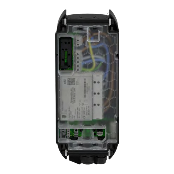
Please observe the safety instructions at the beginning of these installation instructions. The eCLICK can be mounted on a suitable wall or in the ePOLE (duo). Included in delivery... - Page 7 Installation instructions | CLICK eCLICK – the product details eCLICK Contact guard Cable routing plates Locking bracket Mains board eSMARTMETER (optional) Sealing plug Interface board...
-
Page 8: Before Installing
For wall installation, also ensure that the surface Each eCLICK must be fused with its own RCD and on which the eCLICK is to be installed is even. If its own circuit breaker in the pre-installation. No the surface is uneven, it may be difficult to install additional electrical devices may be integrated in and moisture may penetrate. - Page 9 In addition, the cable cross-section of the supply cable is selected according to its length. Important When the eCLICK is mounted in the ePOLE side-by- side, ePOLE back-to-back or ePOLE duo, each and every eCLICK must be provided with its own RCD and circuit breaker.
-
Page 10: Installation
Please note the following summary of the most important installation steps: 13. Make sure that the contact guard is snapped into place in the eCLICK. Use the provided Consultation with the grid operator. seal to secure the contact guard on the... - Page 11 Installation instructions | CLICK Charging power 3.7 kW; 11 kW 7.4 kW; 22 kW Charging current 16 A 32 A Example F204A, 4-pole, 25/0,03 A ABB F204A, 4-pole, 40/0,03 A ABB Standards DIN EN 61008-1/DIN EN 61008-2-1 DIN EN 61008-1/DIN EN 61008-2-1 Type Operating voltage 230/400 V AC...
- Page 12 The eCLICK cannot be connected directly to a TN-C mains. If the pre-installation presents a transfer point from a TN-C to a TN-C-S mains, the eCLICK may be connected to the latter according to TN-C-S description. In other words, the TN-C mains must be...
- Page 13 L1, N, PE, eCLICK three-phase connection: L1, L2, L3, N, PE. An IT mains is not supported. The eCLICK must not be connected directly to an IT mains! Danger Use only power transmission cables complying with DIN VDE 18015 and designed for voltages of Umax <...
- Page 14 Installation instructions | eCLICK Installation Tools needed To install the eCLICK to a wall or to ePOLE (duo), you will need a spirit level, the drilling template provided in the packaging, a pencil or other marker, an 8 mm drill bit, a screwdriver, an electric drill with step bit, and a cordless screwdriver with torque display.
-
Page 15: Installation Information
(duo). To start, place and screw the eCLICK to the points provided for the rear side of the eCLICK on a flat surface, and this purpose in the ePOLE duo. remove the contact guard. The contact guard is clipped without screws to the eCLICK. - Page 16 For full accessibility to the eBOX, the upper hole should be 1,150 mm above the floor. Screw the eCLICK to the wall using the screws provided. Standard height: 1,500 mm For full accessibility...
- Page 17 When delivered, the contact guard is snapped to four points on the eCLICK. Danger The eCLICK must be installed on a flat surface so that the eCLICK does not deform. Important It is imperative that you insert the provided sealing...
- Page 18 Installation instructions | eCLICK Installation eSMARTMETER cabling Ethernet link (optional) As the last step before installation, eSMARTMETER An Ethernet cable can be used to integrate the cabling must be carried out. eBOX in the customer’s network. It is important to know the connections on the interface board Consult the figure to wire the eSMARTMETER to for the Ethernet connection.
- Page 19 L1 L2 L3 N Sub-distribution M20 cable gland Circuit 40 A breaker Replace the routing plate in the eCLICK, and mechanically press it on firmly to ensure tightness. coupled 12 V/24 V DC 2 A max. Feed the network cable through the M20 cable...
- Page 20 Document Center at docs.compleo- The grid control box connector can connect cs.com the eCLICK to an external control box. The interface board features 2 connection options for Before activation, note the switching states and connecting the grid control box.
-
Page 21: Electrical Connection
– has no facilities for the attachment of additional ventilation components. Important The eCLICK can be connected to both the single- and the three-phase output of the sub-distribution. Illustrated, however, are the three-phase connections only. If the connection is single-phase, connect only tp L1, N, and PE. - Page 22 Strip a generous length of insulation from Important the cable before inserting it in the eCLICK. If single-phase connection is required, the mains This will simplify rerouting and subsequent board or eSMARTMETER must not be connected at L2 eSMARTMETER installation.
- Page 23 Installation instructions | CLICK Scenario B: eCLICK electrical connection with eSMARTMETER, simple supply Detach the cable routing plate from the top Important (T) or the bottom (B). If single-phase connection is required, the mains board or eSMARTMETER must not be connected at L2...
- Page 24 (separate power supply line for self-supply) Cut the cable to a length longer than necessary. Introduce the supply cable into the eCLICK from This will simplify rerouting and subsequent the top (T) or the bottom (B). Before you can eSMARTMETER installation.
- Page 25 M20 cable gland. the cable routing plate and cut them to length. Then replace the cable routing plate. The Replace the routing plate in the eCLICK, and eSMARTMETER supply cables must be placed on press it on firmly to ensure tightness.
- Page 26 3. Use the provided seal to secure the contact Danger guard on the eCLICK in such a manner that There is a risk of electric shock and danger to life unauthorised removal of the contact guard is and limb.
- Page 27 LAN 1 RJ45 (deactivated) Connect the white ribbon data cable of the eBOX to port 1 on the left side of the eCLICK. Communication via LAN or SIM card can only be ensured when the black and white ribbon data 90°...
- Page 28 Now place the eBOX carefully on the eCLICK and push it firmly in the middle with the other hand until it stops Be careful not to exert excessive pressure on the circle LEDs.
- Page 29 Please note down the number of phases you have connected and the maximum current on the next page of these installation instructions and on the adhesive label affixed to the eCLICK. The customer can then configure the system independently after a replacement.
- Page 30 You have the option of connecting your eBOX Configuring via eCONFIG app to the Compleo backend or a third-party backend of your choice: You can download the required app via the following QR code: Via Compleo backend With your purchase of the eOPERATE software service, your product’s system was automatically...
-
Page 31: Maintenance & Repair
Make sure that all components are dry during disassembly. Important When disassembling the eBOX, make sure that the eBOX is carefully removed from the eCLICK so that the flat ribbon data cables, the eCLICK and the eBOX are not damaged during disassembly. - Page 32 Locations & Contact information...
- Page 33 Compleo Charging Solutions GmbH & Co. KG Compleo CS Nordic AB Ezzestraße 8 Derbyvägen 4 44379 Dortmund, Germany 212 35 Malmö, Sweden +49 231 53492370 +46 40 6850500 info@compleo-cs.com info.sweden@compleo-cs.com compleo-charging.com compleocs.se Compleo Charging Software GmbH Compleo Charging Solutions GmbH Ezzestraße 8...
- Page 34 The power to move Compleo Charging Solutions GmbH & Co. KG Ezzestraße 8 44379 Dortmund Germany info@compleo-cs.com ©2023 Compleo. All rights reserved. compleo-charging.com This document may not be copied or reproduced in any form or by any means, in whole or in part, without written permission.
Need help?
Do you have a question about the eCLICK and is the answer not in the manual?
Questions and answers