Table of Contents
Advertisement
Quick Links
Advertisement
Table of Contents

Related Manuals for EAW UMX.96

Summary of Contents for EAW UMX.96
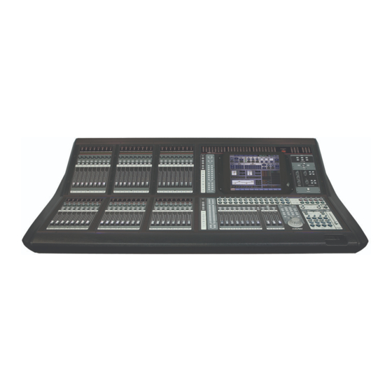
- Page 2 UMX.96 DIGITAL LIVE CONSOLE...
-
Page 3: Table Of Contents
Table of Contents EAW UMX.96 Owner’s Manual Table of Contents For Version 1.0 Chapter 0: Important Safety Instructions ..............0-1 Chapter 1: Introduction ....................1-1 About This Manual ........................1-2 Terminology and Conventions ....................1-2 Notes, Cautions, Warnings, Examples ..................1-3 Chapter 2: General Topics .....................2-1 Features ............................ - Page 4 Table of Contents EAW UMX.96 Owner’s Manual Chapter 4: Connections ....................4-1 The Front Panel Connections ....................4-1 The Rear Panel Connections ....................4-2 4.2.1 Mic/Line Inputs ......................4-3 4.2.2 Stereo Inputs ......................4-3 4.2.3 Outputs ........................4-4 4.2.4 Utility Connections ....................4-5 4.2.5...
- Page 5 Table of Contents EAW UMX.96 Owner’s Manual 8.2.2 Lower Section ......................8-6 8.2.2.1 Gain Pad ....................8-6 8.2.2.2 48V ......................8-6 8.2.2.3 Delay ....................... 8-6 8.2.2.4 Trim ......................8-7 8.2.2.5 HPF Button ....................8-7 8.2.2.6 LPF Button ....................8-7 8.2.2.7 Polarity Invert Button ................
- Page 6 Table of Contents EAW UMX.96 Owner’s Manual Chapter 11: Touch and Spin ..................11-1 11.1 Navigation Area ........................11-1 11.2 User Keys ..........................11-2 11.3 Mute Group Masters ......................11-2 Chapter 12: Touchscreen Interface ................12-1 12.1 Navigation ..........................12-1 12.2 Channel Button ........................12-3 12.2.1 Current Channel Display ..................12-3 12.2.2...
- Page 7 Table of Contents EAW UMX.96 Owner’s Manual 12.2.9 Analog Input Inserts Tab ..................12-20 12.2.9.1 Inserts Edit Menu ................12-20 12.2.10 Stereo Channels 1-8 Overview Tab ..............12-21 12.2.10.1 Stereo Channels Overview Edit Menu ..........12-21 12.2.11 Stereo Channel Delay Tab ..................12-22 12.2.11.1 Stereo Channel Delay Edit Menu ............12-22 12.2.12 Stereo Channel EQ Tab ..................12-22...
- Page 8 Table of Contents EAW UMX.96 Owner’s Manual 12.2.40 Matrix Inserts Tab ....................12-45 12.2.41 VCA Channel Overview Tab ..................12-46 12.2.41.1 VCA Channel Overview Edit Menu ............12-46 12.2.42 VCA Channel Assignment Tab ................12-47 12.2.42.1 VCA Channel Assignment Edit Menu ..........12-47 12.3 Aux/Group Button .......................12-49 12.3.1...
- Page 9 Table of Contents EAW UMX.96 Owner’s Manual 12.10 Setup button ........................12-85 12.10.1 Operation Tab ......................12-85 12.10.1.1 LR+Mono and LCR Mode ..............12-86 12.10.2 General Tab ......................12-87 12.10.3 Digital Tab ......................12-89 12.10.4 MIDI Tab .........................12-89 12.10.5 Expansion Tab .......................12-90 12.10.6 Administration Tab ....................12-90 12.10.7 Naming Tab ......................12-92...
- Page 10 Table of Contents EAW UMX.96 Owner’s Manual UMX.96 DIGITAL LIVE CONSOLE w w w . e a w . c o m Eastern Acoustic Works One Main Street Whitinsville, MA 01588 USA Tel +1 800 992 5013 Fax +1 800 322 8251 Part No.
-
Page 11: Chapter 0: Important Safety Instructions
Safety Information EAW UMX.96 Owner’s Manual Chapter 0: Important Safety Instructions 1. Read these instructions. 16. This apparatus shall not be exposed to dripping or splashing, and no object filled with liquids, such as vases or beer glasses, shall be placed 2. Keep these instructions. on the apparatus. 3. Heed all warnings. 17. The power supply for this apparatus has been equipped with a 2-pole, 4. Follow all instructions. rocker-style power switch. This switch is located on the front panel and should remain readily accessible to the user. 5. Do not use this apparatus near water. 18. WARNING: Plug the power cord into a power outlet where access to the 6. Clean only with dry cloth. power cord connector is readily accessible in case power disconnection is required. 7. Do not block any ventilation openings. Install in accordance with the manufacturer’s instructions. 19. ATTENTION: This equipment has been tested and found to comply with the limits for a Class A, digital device, pursuant to Part 15 of the 8. Do not install near any heat sources such as radiators, heat registers, FCC Rules, and the rules for Canada under ICES-003 - Feb 04. These stoves, or other apparatus (including amplifiers) that produce heat. - Page 12 Safety Information EAW UMX.96 Owner’s Manual 21. Exposure to extremely high noise levels may cause permanent hearing loss. Individuals vary considerably in susceptibility to noise-induced hearing loss, but nearly everyone will lose some hearing if exposed to sufficiently intense noise for a period of time. The U.S. Government’s Occupational Safety and Health Administration (OSHA) has specified the permissible noise level exposures shown in the following chart. According to OSHA, any exposure in excess of these permissible limits could result in some hearing loss. To ensure against potentially danger- ous exposure to high sound pressure levels, it is recommended that all persons exposed to equipment capable of producing high sound pres- sure levels use hearing protectors while the equipment is in operation. Ear plugs or protectors in the ear canals or over the ears must be worn when operating the equipment in order to prevent permanent hearing loss if exposure is in excess of the limits set forth here. Duration, Sound Level Typical Example per day in dBA, Slow hours Response Duo in small club Inside a subway train Very loud classical music Locomotive at 50 feet 0.5 0.25 or less 115 Loudest parts at a rock concert Correct disposal of this product. This symbol indicates that this product should not be disposed of with your household waste, according to the WEEE Directive (2002/96/EC) and your national law. This product should be handed over to an authorized collection site for recycling waste electrical and electronic equipment (EEE). Improper handling of this type of waste could have a possible negative impact on the environment and human health due to potentially hazardous substances that are generally associated with EEE. At the same time, your cooperation in the correct disposal of this product will contribute to the effective usage of natural resources. For more information about where you can drop off...
- Page 13 Safety Information EAW UMX.96 Owner’s Manual EC - Declaration of Conformity Manufacturer: Eastern Acoustic Works – USA May 2008 Declares that the following product(s) have been tested and passed all relevant requirements as described below by the appropriate European Direc- tives as they apply to Professional Audio Products. Product Model(s): UMX.96 Description : Digital Mixing Console Safety Directive(s): EN60065 – 2002 EMC D irective(s): EN55103-1 [Radiated / Conducted Emissions] EN55103-2 [Radiated / Conducted Immunity] 2004/108/EEC Directive Low Voltage Directive: 7 3/23/EEC Markings Directive: 93/68/EEC The Technical Report/File is maintained at: LOUD Technologies Inc. 16220 Wood-Red Road NE Woodinville, WA. 98072 USA Authorized Representative: Tel: +1 425 892 6500 Kevin Cyrus Tel: +1 866 858 5832 Director of Compliance Fax: +1 425 487 4337 Loud Technologies Inc. e-mail: info@eaw.com...
- Page 14 Safety Information EAW UMX.96 Owner’s Manual UMX.96 DIGITAL LIVE CONSOLE...
-
Page 15: Chapter 1: Introduction
DSP processing for a zone, array, or even a specific loudspeaker. The UMX.96 offers 24-bit, 96-kHz performance with expandable on-board 56 x 44 analog I/O, 3 x 12 inte- grated loudspeaker processing, and the first full integration of the EAW Smaart® measurement and analysis platform. -
Page 16: About This Manual
Introduction EAW UMX.96 Owner’s Manual About This Manual This manual is designed to be accessible, with subsections as complete as practical to minimize having to leaf back and forth looking for the whole story. You shouldn’t have to read the entire manual to figure out how to use this console. -
Page 17: Notes, Cautions, Warnings, Examples
Introduction EAW UMX.96 Owner’s Manual The large knob in the central mix area is referred to as the “Intelligent Encoder. ” The Intelligent Encoder’s tactile feel changes according to its usage. It can have a smooth feel, a detented (click-stepped) feel, it may resist movement or it may spin freely, it may have rotational limits or it may have none. - Page 18 Introduction EAW UMX.96 Owner’s Manual UMX.96 DIGITAL LIVE CONSOLE...
-
Page 19: Chapter 2: General Topics
• 100mm touch-sensitive Penny + Giles motorized faders. • Touch and Spin interface features 15" ultra-bright color touchscreen and dynamically tactile Intelligent Encoder. • Fully integrated EAW Smaart® analysis tools. • Advanced Snapshot management system with snapshot Preview and Update. • Offline show management via UMX-control software. -
Page 20: Master Section
• External Talkback Output for FOH to Monitor Console communications. Hardware Overview All of the inputs and outputs are built into the console frame. In fact looking at the rear of the UMX.96, one could easily confuse it for an analog desk. -
Page 21: Terminology Overview
For each of the 12 outputs, there is also a 6-band equalizer, low-pass and high-pass filters, alignment delay, and output limiter. Terminology Overview A mixing console is a very visual piece of hardware. It is also tactile. A few items on the UMX.96 need their own unique names along with some explanation. 2.4.1... -
Page 22: Scribble Strips
2.4.3 Touchscreen The UMX.96 uses a 15" inch color touch panel with a native 1024 x 768 resolution. The touch panel is glare and smudge resistant and the LCD display is capable of wide viewing angles with multiple brightness levels. -
Page 23: Chapter 3: Overview
Physical Input to Channel Routing The UMX.96 lets you assign any physical input connector to any channel on the control surface. Ordinarily, the assignment is input 1 to channel 1, input 2 to channel 2, etc. If your cable system forces an organization... -
Page 24: Output Channel To Physical Output Routing
Additional information on the inserts can be found in Section 12.2.9. Aux/Group Busing The UMX.96 uses a shared aux/group system. There are 24 aux/group buses; you get to decide how they’re apportioned. They are inherently mono, but two adjacent buses can be stereo linked. However you choose to configure them —... -
Page 25: Aux Mode
An aux bus cannot. It ends at the balanced output on the rear panel. Since the UMX.96 follows the model of an analog VCA console, you often don’t need groups for submixing since you can use VCAs instead. The few reasons to make a group assignment might include having to apply signal processing to a group of inputs as a whole or to make a special mix that follows the channel fader setting. -
Page 26: Mute Groups
Quick-Start EAW UMX.96 Owner’s Manual Mute Groups The console’s mute group section operates similarly to an analog console. There are eight mute groups. Any channel can be a member of any mute group in any combination, and multiple assignments are allowed. - Page 27 Quick-Start EAW UMX.96 Owner’s Manual The system processor has two modes, standard and advanced, which present the routing and crossover information in two different views. You can toggle back and forth between them without affecting audio processing in anyway. • Standard Routing View shows the three input signals (A, B, C) routed to any of the 12 outputs in any com- bination.
-
Page 28: Console Configuration, Snapshot, Show, And Preset Storage
Console Configuration, Snapshot, Show, and Preset Storage The UMX.96 can save every parameter associated with its operation with the exception of the power switch. Mixer Configuration, Snapshots, Shows, and Presets are stored on the console’s internal hard disk and can be copied to an attached USB mass storage device (like a thumb drive) for backup and transfer. -
Page 29: Applications
For additional information and more snapshot features, refer to Section 12.14. 3.12 Applications Here are some typical applications for the UMX.96. Of course, we can’t cover every possible configuration, but those listed here describe many common uses of the console. 3.12.1... -
Page 30: Concert Foh
LCR system, but since there are so many crossover channels required, use the speaker manufacturer’s dedicated crossover at the amp racks and run the UMX.96 system processor in advanced routing mode (so you don’t need to deal with the abstraction of a crossover). You use the matrix to drive the system proces- sor because you may need to reduce the separation between left and right while leaving the pan settings alone at the operator’s level. -
Page 31: Concert Monitors
First, you’ll tackle the issue of the signal processing required for each mix. In the old days, you’d have a rack of stuff with at least a 1/3 octave EQ and maybe a comp-limiter, PER MIX. You’ll use the UMX.96’s aux/group processing to handle the per-mix signal processing. -
Page 32: Club Foh And Monitors
• A stereo mix for the engineer’s board recording. • Subs from their own mix. First, put the UMX.96 into LR+CMONO mode (Setup>Operation). We’ll create the overall Left, Right, and Mono mixes from the Matrix. In theory, the matrix will simply pass along the console’s LR/Mono main mixes, without adding anything along the way. -
Page 33: Chapter 4: Connections
Connections EAW UMX.96 Owner’s Manual Chapter 4: Connections The Front Panel Connections These connectors are located at the front edge of the console, on the right side. They are slightly recessed. USB — Two USB type A connectors are used for keyboard, mouse, and USB flash drive back-up and loading. -
Page 34: The Rear Panel Connections
Connections EAW UMX.96 Owner’s Manual The Rear Panel Connections These connectors are located across the expanse of the rear panel. -
Page 35: Mic/Line Inputs
Connections EAW UMX.96 Owner’s Manual 4.2.1 Mic/Line Inputs All of these connections are located on the right half of the rear panel. 48 mic/line inputs — The mic/line inputs have balanced locking XLR connectors, wired according to the AES standard:... -
Page 36: Outputs
Connections EAW UMX.96 Owner’s Manual 4.2.3 Outputs These connections are all located on the left half of the rear panel. System Outputs — These outputs are line level, balanced outputs with XLR male connectors. There are twelve of these connectors for the system processor outputs labeled 1-12. The L, C, and R buses each have balanced Insert send and return available on ¼-inch TRS connectors. -
Page 37: Utility Connections
External Talkback Input — This XLR line level input provides a pass thru option for communication be- tween two consoles. When the UMX.96 is used as a stage monitor console, this input lets the FOH console access the monitor rig for talkback Talkback Output —... -
Page 38: Additional Rear Panel Connections
Connections EAW UMX.96 Owner’s Manual 4.2.5 Additional Rear Panel Connections Power — A cable equipped with a locking multi-pin connector connects the con- sole to its external power supply. See Section 5.3 for more information on the power supply. MIDI I/O — Two Standard 5-pin DIN connectors are provided for MIDI input and output. -
Page 39: Chapter 5: Control Surface Overview
Control Surface Overview EAW UMX.96 Owner’s Manual Chapter 5: Control Surface Overview The control surface of the console includes all of the knobs, faders and buttons that you use to mix the incoming signals. Functionally, the surface is organized into two sections: the channel section on the left and the master section on the right. - Page 40 Control Surface Overview EAW UMX.96 Owner’s Manual • The Bank Select section determines what is assigned to the two fader banks. The upper and lower fader banks can be independently assigned. • The Channel Assign section determines what is assigned to the channel strips, and particularly the func- tion of the channel scribble strip, V-Pot, and ASSIGN buttons.
-
Page 41: The Power Supply
AC line noise. Turn on the Power Output switch on the front panel of the UMX.PS and the UMX.96 will power up. When both supplies are operating properly, the green On, Present, and 48V LEDs for each supply light up. - Page 42 Control Surface Overview EAW UMX.96 Owner’s Manual UMX.96 DIGITAL LIVE CONSOLE...
-
Page 43: Chapter 6: Console Utility Area
Console Utility Area EAW UMX.96 Owner’s Manual Chapter 6: Console Utility Area This section of the console is located above and to the right of the touchscreen. It has four sections: • Meter Bridge • Solo Controls • Monitor Levels •... -
Page 44: Solo Routing
Console Utility Area EAW UMX.96 Owner’s Manual The solo function normally acts in an additive manner on input channels, unless Exclusive Solo is enabled via the Setup>General screen (See Section 12.10.2). Exclusive Solo cancels any existing solo assignment when another channel is soloed. This is especially useful during soundcheck or when soloing output chan- nels. -
Page 45: Monitor Levels
6.4.1 External Input When the UMX.96 is used as a monitor board, the external input lets the FOH console communicate with the monitor board via an analog connection. The EXT TALK IN in- put on the rear panel is a line-level input with its own routing system, configured in the Utility>Talkback screen (see Section 12.9.1). -
Page 46: Talkback
Console Utility Area EAW UMX.96 Owner’s Manual 6.4.2 Talkback This knob controls the level from the Talkback Mic Input sent to the selected destinations on the four backlit buttons labeled MATRIX, LR+C, AUX, and GROUP. This can also be assigned on the Talkback Source Selec- tion page (Utility>Talkback;... -
Page 47: Chapter 7: The Channel Section
The digital version on the UMX.96 also shows the current Channel Assign setting of the V-Pot below it. Sometimes the system temporarily takes over the scribble strip to prompt you or to display parameter values as you make an adjustment. -
Page 48: Select Button
The Channel Section EAW UMX.96 Owner’s Manual Select Button The select buttons typically act in an exclusive manner allowing only one select button to be selected at a time. The selected channel is under control in the Selected Channel section and via the touchscreen. Certain modes have groups of select buttons which blink but ordinarily the selected channel always glows continu- ously and is assigned to the Selected Channel section of the console. - Page 49 The Channel Section EAW UMX.96 Owner’s Manual The solo button can also be configured to simultaneously select the channel and assign it to the Selected Channel and/or to the touchscreen by enabling Select Follows Solo. This configuration setting is located on the Setup>General screen of the touchscreen.
- Page 50 The Channel Section EAW UMX.96 Owner’s Manual UMX.96 DIGITAL LIVE CONSOLE...
-
Page 51: Chapter 8: Bank Select And Channel Assign
Channel Bank select buttons. In addition, the UMX.96 has two user banks that let you have it your way. In the past, the input list pretty much determined how things came up on the faders. The first input on the stage box ended up at fader 1 on the console. -
Page 52: Master Bank Selection
Bank Select and Channel Assign EAW UMX.96 Owner’s Manual USER 1 and 2 —These buttons allow access to the two user-defined custom banks of 24 channels. In the user bank, any input and output channel can be combined via the user bank assign screen. -
Page 53: Channel Assign Section
Bank Select and Channel Assign EAW UMX.96 Owner’s Manual Now press the flashing ASSIGN button on Channel 8 to assign Master Bank STEREO 1-8 to the first set of 8 faders. Now both the MATRIX 1-8 button and the STEREO 1-8 button remain lit, as both are still assigned, and ANALOG 1-24 remains lit as well. -
Page 54: Dynamics Buttons
Bank Select and Channel Assign EAW UMX.96 Owner’s Manual A currently assigned channel’s ASSIGN button lights white when either of these chan- nel assign switches are selected. The scribble strip displays the channel name and the safe status. To assign a channel or fader to Channel Safe or Fader Safe, enable one of the Snapshot Safe buttons in the center Channel Assign area. -
Page 55: Upper Channel Assignment Area Summary
Bank Select and Channel Assign EAW UMX.96 Owner’s Manual 8.2.1.5 Upper Channel Assignment Area Summary The following table summarizes the above information in tabular form. Lower Channel Assign Area and Channel Strip Summary Channel Assign Button Channel Strip Name Description... -
Page 56: Lower Section
Bank Select and Channel Assign EAW UMX.96 Owner’s Manual 8.2.2 Lower Section The lower Channel Assign section controls the following channel functions: • The Preamp buttons configure frequently accessed channel strip parameters: micro- phone preamp input GAIN, PAD, 48V phantom, polarity INV, DELAY, digital TRIM, PAN, HPF and LPF. -
Page 57: Trim
Bank Select and Channel Assign EAW UMX.96 Owner’s Manual 8.2.2.4 Trim The TRIM Channel Assign button allows for individual channel control of the ±15 dB digital trim. The digital trim control is located ahead of all of the channel digital signal processing. -
Page 58: Polarity Invert Button
Bank Select and Channel Assign EAW UMX.96 Owner’s Manual 8.2.2.7 Polarity Invert Button The light blue INV Channel Assign button allows for individual channel activation of 180 degree polarity inversion, which is available on all mono input channels. Press the AS- SIGN button for the channel to turn polarity invert on or off. -
Page 59: Lower Channel Assign And Channel Strip Summary
Bank Select and Channel Assign EAW UMX.96 Owner’s Manual 8.2.2.9 Lower Channel Assign and Channel Strip Summary The following table summarizes all above information in tabular form. Lower Channel Assign Area and Channel Strip Summary Channel Assign Button Channel Strip... -
Page 60: L/R, Ctr, And Aux/Group Assigns
(the ASSIGN button glows green when enabled). On an analog console, the number of groups and auxes is normally fixed. The UMX.96 uses a shared mix bus architecture that shares the mix buses between group and aux as- signments. -
Page 61: Aux Pan Button
8.2.3.4 Aux Mode Button The AUX MODE button in the Channel Assign section essentially converts the UMX.96 to a monitor mixing console when pressed. It lights purple to indicate this in an obvious way since it is a fairly drastic change in console operation. Enabling Aux Mode changes the channel faders on both the upper and lower banks to instead control the aux send levels from the channels. -
Page 62: Effects Buttons
Bank Select and Channel Assign EAW UMX.96 Owner’s Manual Press either of the VCA bank buttons (see section 8.1.2) to switch back to standard VCA fader operation and simply press any Aux/Group button to switch back to Aux/Group master operation with that Aux/Group under control. -
Page 63: Custom Channel Assign Mode
Bank Select and Channel Assign EAW UMX.96 Owner’s Manual Custom Channel Assign Mode A channel can have its assign button, V-Pot and scribble strip locked to a specific function independent of any global Channel Assign function changes. This is called a Custom Channel Assignment. - Page 64 Bank Select and Channel Assign EAW UMX.96 Owner’s Manual UMX.96 DIGITAL LIVE CONSOLE 8-14...
-
Page 65: Chapter 9: The Selected Channel
The Selected Channel EAW UMX.96 Owner’s Manual Chapter 9: The Selected Channel The Selected Channel provides complete functionality for one channel of the console at a time. This en- hanced control area provides the assortment of controls and displays normally found on an analog console channel strip. -
Page 66: Aux/Groups Area
The Selected Channel EAW UMX.96 Owner’s Manual Aux/Groups Area This area contains 24 V-Pots, one for each aux/group send for the selected channel. Make the aux/group choice from the Aux/Group setup screen or by pressing Shift+ button in the Channel Assign area (see Sec- tions 8.2.3.1 and 12.3 for details). -
Page 67: Gate/Compressor Area
The Selected Channel EAW UMX.96 Owner’s Manual Gate/Compressor Area This group of controls affects the Gate/Expander and the Compressor. Only mono input channels have gates/expanders. All channels except internal effects returns have compressors. The quick explanation of a gate is: signals below the threshold level are muted, while signals above the threshold get to pass through. - Page 68 The Selected Channel EAW UMX.96 Owner’s Manual The Gate/Compressor area can also be controlled via the touchscreen and this method of control offers some useful visual devices (see Section 12.2.7). From the control surface, each V-Pot controls its correspond- ing parameter as described in the table below:...
-
Page 69: Preamplifier Area
The Selected Channel EAW UMX.96 Owner’s Manual Preamplifier Area The preamplifier controls access all preamp related parameters such as the input gain, pad, polarity, trim, and 48V phantom power for the Selected Channel. 9.4.1 Gain V-Pot The GAIN V-Pot allows individual channels equipped with mic preamps to control the preamplifier’s gain (in 1 dB increments). -
Page 70: Selected Channel Preamplifier Control Summary
The Selected Channel EAW UMX.96 Owner’s Manual 9.4.6 Selected Channel Preamplifier Control Summary The following table summarizes the Selected Channel’s PreAmp area: Selected Channel Preamp Controls Chan. Assign Area V-Pot Data Display Button Description Knob LEDs Bottom Ctrl/ Button Ctrl/... -
Page 71: Equalizer Area
The Selected Channel EAW UMX.96 Owner’s Manual Equalizer Area The Equalizer controls access all EQ related parameters such as high-pass filter (HPF), low-pass filter (LPF), and EQ for the Selected Channel. 9.5.1 4-band EQ Every input and output channel has a 4-band EQ except for the Main Left, Right, and Center/Mono (which feed a 6-band in the system processor). -
Page 72: Shelf
The Selected Channel EAW UMX.96 Owner’s Manual 9.5.1.6 SHELF These buttons are available for the LOW and HI EQ bands. When engaged, the EQ becomes a shelving filter rather than a parametric filter. The Q control becomes inactive when SHELF is engaged. -
Page 73: Channel Fader Area
The Selected Channel EAW UMX.96 Owner’s Manual Channel Fader Area The Pan V-Pot allows for individual channel panning to L-R or LCR, depending on the console’s mode of operation. • In LR + Mono mode, the pan control acts as a stereo control; it has two outputs, left and right. The assign switches still assign to their respective Left, Right, and Center/Mono buses, but the Center/Mono assign is post-fader but pre-pan. - Page 74 The Selected Channel EAW UMX.96 Owner’s Manual UMX.96 DIGITAL LIVE CONSOLE 9-10...
-
Page 75: Chapter 10: Vca Control Section
VCA Control Section EAW UMX.96 Owner’s Manual Chapter 10: VCA Control Section The VCA (Virtual Control VCA Control Attenuator) section of- v c 1 v c 2 v c 3 v c 4 v c 5 v c 6 v c 7... -
Page 76: Output 31-Band Eq Control
VCA Control Section EAW UMX.96 Owner’s Manual Mute Button — The red MUTE button lights when the corresponding VCA master is muted and is unlit when it is active. Any time the VCA is muted, any channels assigned to the VCA group are also muted. This is indicated on the control surface by flashing the mute buttons on these channels. -
Page 77: Master Faders Area
VCA Control Section EAW UMX.96 Owner’s Manual • If the selected channel is already displayed in the master section (e.g., it is a VCA), then the displayed channels do not change but the VCA buttons still both light to illustrate that the faders are in channel fol- low mode. - Page 78 VCA Control Section EAW UMX.96 Owner’s Manual UMX.96 DIGITAL LIVE CONSOLE 10-4...
-
Page 79: Chapter 11: Touch And Spin
A rotary switch has sev- eral detents throughout its rotation. The UMX.96’s Intelligent Encoder does all of this under software control by changing its feel for the parameter under control. -
Page 80: User Keys
Touch and Spin EAW UMX.96 Owner’s Manual 11.2 User Keys Eight User Keys (1-8) can be easily assigned to instantly access a particular screen or function. These but- tons allow associating a particular function/preset/control with a particular channel and then assigning that combination to one of the user buttons. -
Page 81: Chapter 12: Touchscreen Interface
Touchscreen Interface EAW UMX.96 Owner’s Manual Chapter 12: Touchscreen Interface The console can be controlled entirely from the touchscreen and Intelligent Encoder. This color LCD display accesses every part of the console’s components. It provides a quick overview of what is happening in a way that an analog console just can’t do. - Page 82 Touchscreen Interface EAW UMX.96 Owner’s Manual The navigation buttons are (in on-screen order): Button Name and Description Section Channel — All channel controls 12.2 Aux/Group — Aux/Group setup 12.3 Configure Aux/Group and link sends for stereo operation Matrix — Matrix output section 12.4...
-
Page 83: Channel Button
Touchscreen Interface EAW UMX.96 Owner’s Manual 12.2 Channel Button This button displays the Channel>Overview screen, which is used for both input and output channels. The analog input channels 1-48 have the most comprehensive version of this screen. Other input and output channel types have variations of this screen, but the general layout is always the same, making finding the different parts consistent. -
Page 84: Link Button
Touchscreen Interface EAW UMX.96 Owner’s Manual Note: You can give channels your own names. Do this via Setup>Naming. The Channel Select screen lets you access the following inputs, outputs, VCAs or banks: • Analog Inputs 1-48 • Expansion inputs 49-96 (only when expansion chassis is present) •... -
Page 85: Edit Button
Touchscreen Interface EAW UMX.96 Owner’s Manual 12.2.3 Edit Button This button accesses the Edit menu for the current screen. Edit menus vary from screen to screen. They pro- vide shortcuts for the current screen and and are described with each individual screen. -
Page 86: Gain Control
Touchscreen Interface EAW UMX.96 Owner’s Manual 12.2.4.2 Gain Control The GAIN control sets the analog input gain and is displayed as a knob and numerical readout. It is adjustable via Touch and Spin. The displayed gain value is calculated by adding the preamp gain and the pad value, if present, so the number shown is the actual amount of gain applied to the input. -
Page 87: Pre-Dsp Level Meter
Touchscreen Interface EAW UMX.96 Owner’s Manual 12.2.4.7 Pre-DSP Level Meter The meter displays the signal in the digital domain after the input delay but before the pre-DSP insert. Normally, the analog input pre-DSP level meter shows the same signal as the meter found on the channel strip of the console, but with higher resolution. -
Page 88: Post-Dsp Level Meter
See also Section 12.9.6. 12.2.4.17 VCA Groups In the UMX.96, VCA stands for Virtual Con- trol Attenuator, whose action and usage is the same as a VCA found in an analog console. -
Page 89: Mute Button
Touchscreen Interface EAW UMX.96 Owner’s Manual 12.2.4.18 Mute Button The Mute button mutes the channel in the same manner as pressing the MUTE but- ton on the control surface. The Mute button supersedes any mute commands from the group mute or VCA systems; if it is pressed, the channel remains muted regardless of the state of any mute groups or VCAs. -
Page 90: Equalizer
Touchscreen Interface EAW UMX.96 Owner’s Manual Touch the COMP/LIM IN button to turn on or off the Compressor, and touch the Hard Knee/Soft Knee switch to toggle between the two modes. Touching anywhere else in this area takes you to the Dynamics tab where you can make further adjustments to the dynamics settings. -
Page 91: Analog Input Delay Tab
Touchscreen Interface EAW UMX.96 Owner’s Manual 12.2.5 Analog Input Delay Tab The Delay tab accesses the channel’s alignment delay, used to adjust the arrival time of a source via the sound system to its acoustical origin. This delay is adjustable from 0 to 150 ms for input channels and 0 to 700 ms for output channels and is adjustable in 0.5 ms steps via touch and spin. -
Page 92: Analog Input Eq Tab
Touchscreen Interface EAW UMX.96 Owner’s Manual 12.2.6 Analog Input EQ Tab The channel equalizer has four fully parametric bands. In addition, the two outside bands may be converted from parametric to shelving. A window displays the composite EQ curve of all four bands overlaid with the HPF and LFP curves. -
Page 93: Smaart And Rta View
Touchscreen Interface EAW UMX.96 Owner’s Manual Note: Although the Q control does adjust the bandwidth of a filter, the Q value itself is dimensionless; it has no unit of measurement. Some equalizers use the fractional bandwith of the filter, measured in octaves, to express this parameter. -
Page 94: Analog Input Dynamics Tab
Touchscreen Interface EAW UMX.96 Owner’s Manual 12.2.7 Analog Input Dynamics Tab Touching the dynamics block on the Overview screen or this tab brings up the Dynamics screen. A unique display shows simultaneous input, GR, and output metering for both gate and compressor with an input/ output graph. -
Page 95: Gate Operation And Graphic Display
Touchscreen Interface EAW UMX.96 Owner’s Manual • RATIO control — Expander mode only. Sets the amount of gain reduction applied as the signal falls below threshold. A gate is an expander with an infinite ratio and infinite range. • ATTACK control — Determines how quickly the gate/expander opens once the signal is above threshold. -
Page 96: Expander Operation And Graphic Display
Touchscreen Interface EAW UMX.96 Owner’s Manual At this point, the gate is open. Once the gate opens, input signals are passed unchanged to the output. Any change in the input level that is below threshold appears at the output quieter by the setting of the range level (16 dB). -
Page 97: Compressor Operation And Graphic Display
Touchscreen Interface EAW UMX.96 Owner’s Manual threshold, the output signal is reduced in level based on the ratio setting. For more information about this processor, refer to the discussion in Section 9.3. The compressor has the following features: • Input, Reduction, and Output level meters — These three meters show the input level, output level, and amount of gain reduction. -
Page 98: Dynamics Edit Menu
Touchscreen Interface EAW UMX.96 Owner’s Manual In this example, the Threshold setting is –24 dBFS, the Ratio setting is 1:2.2, which means that a 2.2 dB input change becomes a 1 dB output change. The Gain setting is 0 dB. Note how the gain line makes a smooth curve as it crosses the threshold line;... -
Page 99: Aux/Groups Edit Menu
Touchscreen Interface EAW UMX.96 Owner’s Manual The picture of Aux Send 5 identifies the different parts of each aux send. The top is the Aux name. If you have changed the name, the long custom name will appear. Press the IN button to route signal from the selected channel to the send. -
Page 100: Analog Input Inserts Tab
Touchscreen Interface EAW UMX.96 Owner’s Manual 12.2.9 Analog Input Inserts Tab This tab allows control of the pre-DSP and post-DSP digital inserts. A drop-down list allows selection of the insert from the available choices. The list is separated into software DSP inserts and hardware inserts. The IN buttons allow enabling the inserts and for software DSP inserts, the Edit buttons allow quick access to the DSP processor control screen. -
Page 101: Stereo Channels 1-8 Overview Tab
Touchscreen Interface EAW UMX.96 Owner’s Manual 12.2.10 Stereo Channels 1-8 Overview Tab The functionality of the stereo channels is mostly identical to the mono mic channels except for the follow- ing main differences (refer to Section 12.2.4): • There is no mic preamp. Instead there is 20 dB of analog line gain adjustable with Touch and Spin. The ad- ditional gain is helpful in accommodating consumer-type sources. -
Page 102: Stereo Channel Delay Tab
Touchscreen Interface EAW UMX.96 Owner’s Manual 12.2.11 Stereo Channel Delay Tab The stereo channel’s Delay works identically to the mono analog channel delay. Both the left and right side of the stereo channel are delayed by the same amount. See Section 12.2.5 for details. -
Page 103: Stereo Channel Compressor Edit Menu
Touchscreen Interface EAW UMX.96 Owner’s Manual The stereo channels have a stereo compressor; there is no gate/expander. Thus, the gate processing block is missing on the overview screen. Touching the Compressor’s block also gets you to this point. Since this is a stereo compressor, the left and right channels are mixed to mono for the key signal, keeping the stereo image stable even during gain reduction. -
Page 104: Stereo Channel Inserts Tab
Touchscreen Interface EAW UMX.96 Owner’s Manual 12.2.15 Stereo Channel Inserts Tab This tab allows control of the pre-DSP and post-DSP digital inserts. A drop-down list allows selection of the insert from the available choices. The list is separated into software DSP inserts and hardware inserts. The IN buttons allow enabling the inserts and for software DSP inserts, the Edit buttons allow quick access to the DSP processor control screen. -
Page 105: Stereo Internal Fx Overview Tab
Touchscreen Interface EAW UMX.96 Owner’s Manual 12.2.16 Stereo Internal FX Overview Tab The four internal effects channels are scaled down versions of the input channels. The FX module is consid- ered part of the channel’s DSP processing. Thus, the channel is not only the signal processing for the FX, it is also the point at which you select the internal FX processor. -
Page 106: Internal Fx Edit Menu
Touchscreen Interface EAW UMX.96 Owner’s Manual • Mix Assign buttons — These buttons assign the channel to the L/R and CENTER channels depending on LR/C or LCR mode of the console. See Section 12.10.1.1. • Aux/Groups — This is the overview screen for the channel’s Aux/Group sends. Touching this part of the overview screen displays the Aux/Groups control screen. -
Page 107: Reverb
Touchscreen Interface EAW UMX.96 Owner’s Manual Note that effects presets include both the effect and the three-band EQ following the effect. Changing the preset will change the three-band EQ. Storing an effect preset will store the three-band EQ setting. FUNCTION... -
Page 108: Reverb+Gate
Touchscreen Interface EAW UMX.96 Owner’s Manual Roll Off: This provides a 24 dB/octave low-pass filter at the output of the reverb DSP. This allows you to roll off the level of the audio range above the frequency set by this control. The range is 500 Hz to 20 kHz, in scaled steps. -
Page 109: Mono Delay
Touchscreen Interface EAW UMX.96 Owner’s Manual 12.2.17.3 Mono Delay The mono delay provides an echo effect with a mono delay line and has the following controls: Delay: This determines how long the delayed signal is delayed from the original signal. It ranges from 0 to 1600 ms (1.6 seconds). -
Page 110: Ping Pong Delay
Touchscreen Interface EAW UMX.96 Owner’s Manual 12.2.17.5 Ping Pong Delay The ping pong delay works the same as the stereo delay, with the exception that the feedback is routed to the opposite channel, producing a bouncing sound as the delayed signal bounces from left to right. It has the same controls as the stereo delay described previously. -
Page 111: Flanger
Touchscreen Interface EAW UMX.96 Owner’s Manual 12.2.17.7 Flanger The flange effect is very similar to the chorus effect, and has the same controls as previously described for the chorus effect with the addition of a Regeneration control. A flanger has a shorter Pre Delay time, typi- cally from 1 ms to 10 ms. -
Page 112: Internal Fx Eq Tab
Touchscreen Interface EAW UMX.96 Owner’s Manual 12.2.18 Internal FX EQ Tab The internal FX equalizer has 3 bands, with swept shelving low and high controls and a full-range parametric boost/cut control, all adjustable via Touch and Spin. These are the same controls that you access when you press the EDIT EQUALIZER button in the Effects tab. -
Page 113: Internal Fx Aux/Groups Tab
Touchscreen Interface EAW UMX.96 Owner’s Manual 12.2.19 Internal FX Aux/Groups Tab This tab displays the Aux/Groups screen for the effects channel. Touching the Aux/Groups overview area on the Overview screen also brings you here. Everything here is identical to the Aux/Groups screen for the analog input channels, with one exception: you can’t send the effect back to its own send as illustrated in the figure below. -
Page 114: Aux/Groups 1-24 Overview Tab
Aux Overview The UMX.96 is a shared aux/group console. There are 24 Aux/Group sends; you select which ones are groups and which ones are auxes on the Aux/Group screen (see Section 12.3 for details). You can have 24 Aux sends, or 24 Group sends, or any combination of auxes and groups that adds to 24. - Page 115 Touchscreen Interface EAW UMX.96 Owner’s Manual Grp Overview • Comp/EQ IN buttons — Enables the compressor and EQ. The small displays show a miniature view of the compressor transfer curve and the EQ graph. You can adjust the processors via the EQ or Comp tabs at the top of the touchscreen or by touching the screens below the Mute Groups or VCA Groups buttons.
-
Page 116: Aux/Groups Overview Edit Menus
Touchscreen Interface EAW UMX.96 Owner’s Manual • Compressor — Compressor/Limiter, the same as in the mono input channels. • 31-band EQ — 31-band EQ / Smaart analyzer combination. The Graphic Equalizer/Smaart combination is described in Section 12.6. 12.2.20.1 Aux/Groups Overview Edit Menus The Aux/Groups edit menus are the same as those for the mono analog channels. -
Page 117: Aux/Groups Rta 31 Tab
Touchscreen Interface EAW UMX.96 Owner’s Manual 12.2.23 Aux/Groups RTA 31 Tab In addition to the four-band parametric equalizer found in the input channels, the Aux/Group sends have a 31-band ISO-center graphic equalizer combined with an integral Smaart Real Time analyzer. The equal- izer can be operated directly from the touchscreen (Touch and Spin) or it can be divided into four groups of bands and moved (temporarily) to the eight VCA master faders for control. -
Page 118: Aux/Groups Delay Tab
Touchscreen Interface EAW UMX.96 Owner’s Manual 12.2.24 Aux/Groups Delay Tab Although this is an output delay for the Aux/Grp channel, it operates the same as the input delay on the analog input channels, with up to 700 ms delay. Refer to Section 12.2.5 for more information. -
Page 119: Lrc Overview Tab
Touchscreen Interface EAW UMX.96 Owner’s Manual 12.2.27 LRC Overview Tab Like most of the other output channel screens, the main output screen is based on the overview screen for the mono input channel. Since this is an output channel, only the following elements are present: The LRC Overview screen has the following elements: •... -
Page 120: Lrc Comp Tab
Touchscreen Interface EAW UMX.96 Owner’s Manual 12.2.28 LRC Comp Tab The compressor for the LRC system outputs works the same as it does on the analog input channels. Refer to Section 12.2.7.4 for an explanation of the controls for the compressor. -
Page 121: Lrc Channel List Tab
Touchscreen Interface EAW UMX.96 Owner’s Manual 12.2.31 LRC Channel List Tab This tab displays a columnar checklist of inputs, their long names, and a checkbox to the right of each name. Clicking the checkbox assigns that input to the currently selected L/R/C output channel. At the right of this screen is a scrollable list of all the assigned channels. -
Page 122: Matrix 1-8 Overview Tab
This makes the Matrix in the UMX.96 extremely useful for situations that a normal analog console matrix with fixed input sources could never be used. -
Page 123: Matrix Overview Edit Menu
Touchscreen Interface EAW UMX.96 Owner’s Manual • Insert Post EDIT button — Post-DSP digital insert point. Touching the EDIT button accesses the Inserts screen, the same as touching the Inserts tab. The readout below the button displays the name of the selected insert device. - Page 124 Touchscreen Interface EAW UMX.96 Owner’s Manual Select your source from this screen by narrowing your selection by touching a button under the Bank Select column to choose a group of channels. Then, touch the SELECT button over the channel name you wish to select.
-
Page 125: Matrix Input Mixer Edit Menu
Touchscreen Interface EAW UMX.96 Owner’s Manual 12.2.35.1 Matrix Input Mixer Edit Menu The Input Mixer Overview screen’s Edit menu has the following commands: • Save Matrix Preset As — Saves the current state of the current matrix input mixer under a user-defined name. -
Page 126: Vca Channel Overview Tab
12.2.41 VCA Channel Overview Tab In the UMX.96, the VCA (a.k.a. Virtual Control Attenuator) section performs the same function as the VCA (Voltage Controlled Amplifier) section in an analog console: it acts as a master fader to a user-assigned group of faders. You can think of them in the same way even though the words are different. Similarly, since the grouping is only virtual, you can’t use the VCA section to create a group of channels for combined... -
Page 127: Vca Channel Assignment Tab
Touchscreen Interface EAW UMX.96 Owner’s Manual 12.2.42 VCA Channel Assignment Tab The Assignments Tab is one way to assign and unassign channels to a VCA . It provides a view of many chan- nels at once, from the standpoint of a single VCA master. You can also look at the assignment situation from the other direction, to which VCA masters a given source is assigned, by going to the overview screen for that source channel. - Page 128 Touchscreen Interface EAW UMX.96 Owner’s Manual UMX.96 DIGITAL LIVE CONSOLE 12-48...
-
Page 129: Aux/Group Button
This screen configures the aux/group buses for either Aux or Group operation. The UMX.96 is a shared group/aux console. There are 24 Aux/group sends; you select which ones are groups, which ones are auxes, and which ones are stereo-linked. You can have 24 Aux sends, or 24 Group sends, or any combination of auxes and groups that adds to 24. -
Page 130: Aux/Group Edit Menu
Touchscreen Interface EAW UMX.96 Owner’s Manual 12.3.1 Aux/Group Edit Menu The Aux/Group (setup) screen’s Edit menu has the following command: • Adjust Pre/Post State for All Sends — Accesses a dialog that allows setting the pre/post state for any aux send on all channels at once. -
Page 131: Matrix Button
Touchscreen Interface EAW UMX.96 Owner’s Manual 12.4 Matrix Button You can view all of the matrices at once by touching the Matrix navigation button located at the bottom of the screen. Each matrix mix is represented by a horizontal row. Each row shows 16 sets of displays; one for each input to that matrix. - Page 132 Touchscreen Interface EAW UMX.96 Owner’s Manual UMX.96 DIGITAL LIVE CONSOLE 12-52...
-
Page 133: System Button
Touchscreen Interface EAW UMX.96 Owner’s Manual 12.5 System Button The System navigation button opens the System Processor Overview screen. The system processor is con- figured for 3x12 operation, configured as three 1x4 processors driven from the left, right, and center/mono buses (this can be changed). -
Page 134: Input Source Selection
Touchscreen Interface EAW UMX.96 Owner’s Manual 12.5.1.2 Input Source Selection To change an input source, touch the source name window (A, B, C in the figure) of the desired System Processor Input and select the new source from the Channel Select screen that appears. Choose from the following sources: •... -
Page 135: System Processor Input Delay
Touchscreen Interface EAW UMX.96 Owner’s Manual 12.5.1.6 System Processor Input Delay Touch the Delay button to access the delay screen. The LED below the Delay button indicates when the delay is enabled. The delay provides 0-700 milliseconds of delay in increments of 0.5 ms. The delay interval can be entered as time or distance via Touch and Spin. -
Page 136: Standard Routing
Touchscreen Interface EAW UMX.96 Owner’s Manual Advanced Routing View (shown above) instead allows any output source from the available list to be fed directly into an output leg. In addition, the standard crossover view is replaced with a crossover for each band consisting of a bandpass filter, made by cascading a high-pass and low-pass filter. -
Page 137: Advanced Routing
Touchscreen Interface EAW UMX.96 Owner’s Manual Connections made in the Advanced Routing view are shown with a grey button labeled ADV. See Section 12.5.1.9 below for details. The Standard Routing Crossover can be configured for each set of four output legs. They can be configured as No, 2, 3 or 4 way crossovers. -
Page 138: Crossover Editing - Standard Routing View
Touchscreen Interface EAW UMX.96 Owner’s Manual 12.5.1.11 Crossover Editing – Standard Routing View In standard routing view, you are presented with only the number of band controls for the type of crossover configured (2, 3, or 4-way). Figure 12.5.4 shows the crossover configuration screen for the standard 3-way crossover. Each band has a high-pass filter and a low-pass filter that defines its passband. -
Page 139: Crossover Editing - Advanced Routing View
Touchscreen Interface EAW UMX.96 Owner’s Manual 12.5.1.12 Crossover Editing – Advanced Routing View In Advanced Routing View, each “way” of the multi-way crossover is created and displayed individually. Fig- ure 12.5.5 shows the crossover’s edit screen. You can access all 12 bands of the Output Processor here. -
Page 140: System Processor Output Eq
Touchscreen Interface EAW UMX.96 Owner’s Manual 12.5.1.13 System Processor Output EQ Each of the 12 output legs has one of these equalizers. Functionally, they are identical to the equalizer found in the input processor. Refer to Section 12.5.1.3 except that the high-pass and low-pass filters of the cross- over filters are also displayed here (in both Standard and Advanced Routing Views). -
Page 141: Output Limiter
Touchscreen Interface EAW UMX.96 Owner’s Manual 12.5.1.17 Output Limiter The output limiter can actually function as a compressor or as a limiter, dependent on its ratio setting. Compressor Controls Limiter IN In/Out Threshold GR Threshold 0 to –60 dBFS Attack Attack time 0.1 ms to 300 ms... -
Page 142: Limiters View Tab
Touchscreen Interface EAW UMX.96 Owner’s Manual 12.5.2 Limiters View Tab This tab displays the entire System Processor output limiters from an operational perspective. Every control setting is visible as are input, output, and gain reduction meters. Refer to Figure 12.5.6 below. -
Page 143: Smaart Button
Smaart users will still find the interface familiar. By default, the Smaart Measurement input is fed by the UMX.96 measurement mic input and the Smaart Ref- erence input is fed by the selected channel post-DSP signal. If desired, you can set up a custom set of inputs for measurement and reference. - Page 144 Touchscreen Interface EAW UMX.96 Owner’s Manual Smaart Mode Setting has two radio button options: AUTO which feeds Smaart with the default signals described above and CUSTOM which allows selection of different inputs. Below the custom button are two drop-down lists labeled Measurement and Reference. Touching one will display the Channel Select pop-up to choose a custom signal from the following list: •...
-
Page 145: Effects Button
Touchscreen Interface EAW UMX.96 Owner’s Manual 12.7 Effects Button The Effects navigation button at the bottom of the screen gives you immediate access to the four internal effects processors. Each processor can be set to one of seven different processors using the corresponding Effect Selection buttons. - Page 146 Touchscreen Interface EAW UMX.96 Owner’s Manual UMX.96 DIGITAL LIVE CONSOLE 12-66...
-
Page 147: Routing Button
Touchscreen Interface EAW UMX.96 Owner’s Manual 12.8 Routing button This screen allows routing any physical input into any channel on the console. It also allows any channel to be routed to any output. Finally, you can designate an input/output pair as an insert, which can then be ap- plied to any channel. -
Page 148: Input Routing Tab Edit Menu
Touchscreen Interface EAW UMX.96 Owner’s Manual 12.8.1.1 Input Routing Tab Edit Menu The input routing Edit button has the following commands: • Save Input Routing Preset As — Saves the current routing assignments as a preset under a user-defined name. -
Page 149: Output Routing Tab Edit Menu
Touchscreen Interface EAW UMX.96 Owner’s Manual 12.8.2.1 Output Routing Tab Edit Menu The output routing tab’s Edit menu has the following commands: • Save Output Routing Preset As — Saves the current routing assignments as a preset under a user-de- fined name. -
Page 150: Insert Routing Tab
Touchscreen Interface EAW UMX.96 Owner’s Manual 12.8.4 Insert Routing Tab The Insert Routing Tab allows creation of a hardware I/O pair as a hardware insert that can then be inserted into any digital insert point onto the console. It consists of a three column list showing all created hardware inserts with the following heading: Name, Insert Send, and Insert Return. -
Page 151: Insert Routing Tab Edit Menu
Touchscreen Interface EAW UMX.96 Owner’s Manual 12.8.4.1 Insert Routing Tab Edit Menu The insert routing tab’s Edit Menu has the following commands: • Save Insert Routing Preset As — Saves the insert current routing assignments as a preset under a user- defined name. - Page 152 Touchscreen Interface EAW UMX.96 Owner’s Manual UMX.96 DIGITAL LIVE CONSOLE 12-72...
-
Page 153: Utility Button
Touchscreen Interface EAW UMX.96 Owner’s Manual 12.9 Utility button The Utility navigation button opens the Utility window. This screen reveals additional tabs that aid in the operation of the console: Talkback, Monitors, Tone Gen, SPL Meter, User Banks, Mute Groups, Banks, User Keys, and Meters. -
Page 154: Monitor
Touchscreen Interface EAW UMX.96 Owner’s Manual 12.9.2 Monitor This is the engineer’s monitor section of the console where the engineer controls what they hear through the monitor and phones outputs. The following controls are available: • Monitor Delay — Sets the 0-700 ms delay for the monitor speakers and headphones to allow time align- ment with audio arriving acoustically from the main FOH speakers. - Page 155 Touchscreen Interface EAW UMX.96 Owner’s Manual • Monitor Mode — A 3-position toggle switch allows you to configure the monitor outputs to match your listening environment. Choose from the following options: 2 Speaker Mode — In this mode, the center/mono channel is panned equally between the left and right speakers.
-
Page 156: Tone / Noise Generator Tab
Touchscreen Interface EAW UMX.96 Owner’s Manual • Main to Monitor — Routes the signals from the Left, Right, Center/Mono outputs into the monitor signal path when no channels are soloed. This routing includes the phones. You can use this button (disengage it) to silence the phones when nothing is soloed, which may be useful if you are working in a quiet envi- ronment in close proximity to the audience. -
Page 157: Spl Meter Tab
Touchscreen Interface EAW UMX.96 Owner’s Manual 12.9.4 SPL Meter Tab This tab allows setting up the SPL meter and record log. Note: The SPL Meter is currently not implemented, but will be added in a future update. 12-77... -
Page 158: User Banks Tab
Touchscreen Interface EAW UMX.96 Owner’s Manual 12.9.5 User Banks Tab The user fader banks let you create two banks of 24 faders representing signals from anywhere in the con- sole (inputs, outputs, auxes, groups, VCAs, FX returns, internal FX returns, expansion chassis, stereo channels and the matrix). -
Page 159: User Banks Tab Edit Menu
Touchscreen Interface EAW UMX.96 Owner’s Manual The function buttons are described in detail: • Up Arrow: Moves the selected user bank channel up a position, effectively swapping it with the one above it. • Down Arrow: Moves the selected user bank channel down a position, effectively swapping it with the one below it. -
Page 160: Mute Groups Tab
Touchscreen Interface EAW UMX.96 Owner’s Manual 12.9.6 Mute Groups Tab The Mute Groups tab allows directly setting up all of the mute groups from a single screen. It operates simi- lar to the VCA Assignment tab described previously (see Section 12.2.15.2). A row of numbered buttons at the top selects one of the eight mute groups for editing. -
Page 161: Mute Groups Edit Menu
Touchscreen Interface EAW UMX.96 Owner’s Manual The right column shows the Assigned Channel Overview, a self-sorting list of the current channels that are part of the selected mute group. To remove a channel, follow the above steps to choose the mute group and source channel bank but simply uncheck the channel(s) that you wish to remove. -
Page 162: Bank Assign Tab
Touchscreen Interface EAW UMX.96 Owner’s Manual 12.9.7 Bank Assign Tab The Banks tab gives an overview of which master banks and channel banks are currently assigned and al- lows you to directly assign them. You can also control master bank locking from this screen. -
Page 163: User Keys Tab
Touchscreen Interface EAW UMX.96 Owner’s Manual 12.9.8 User Keys Tab The eight User Keys buttons are located in the Touch and Spin sec- tion of the console between the snapshot buttons and the master mute group buttons. These buttons can be assigned to mixer func- tions via the User Keys tab in the Utility screen. -
Page 164: Meters Tab
Touchscreen Interface EAW UMX.96 Owner’s Manual 12.9.9 Meters Tab This tab displays 24 high resolution bargraph meters which duplicate the Gain Reduction meters for the Gate and Compressor and the selected Channel Meters. These meters follow the assignment made for the Master Bank of Console meters. -
Page 165: Setup Button
Touchscreen Interface EAW UMX.96 Owner’s Manual 12.10 Setup button The Setup navigation button gives you access to another set of tabs for setting the console’s global param- eters. The tabs are: Operation, General, Digital, MIDI, Expansion, Admin, and Naming. 12.10.1 Operation Tab The Operation tab sets up the global LR+Mono or LCR mode for the console as well as other global parameters. -
Page 166: Lr+Mono And Lcr Mode
Solo In Place follows the behavior of Exclusive Solo (see Section 12.10.2). 12.10.1.1 LR+Mono and LCR Mode The UMX.96 has two global operating modes: stereo operation with an independently assignable mono output called LR+Mono, and an LCR operating mode with true LCR panning available from the channels and buses. -
Page 167: General Tab
Touchscreen Interface EAW UMX.96 Owner’s Manual • The L-R pair and Center/Mono master levels and processing are linked by default but the faders can easily be unlinked by holding down the three select buttons. This can also be done via the touchscreen. Press- ing the LINK button above the master faders on the control surface temporarily links/unlinks the Center master fader with/from the LR allowing for the creation of an offset. - Page 168 Touchscreen Interface EAW UMX.96 Owner’s Manual • Screen Follows Select: On or Off (default on) — When enabled, the screen follows the selected channel. If it is disabled, the screen can view and edit a different channel than the console’s Selected Channel.
-
Page 169: Digital Tab
Touchscreen Interface EAW UMX.96 Owner’s Manual 12.10.3 Digital Tab Fixed at 48 kHz internal. The Digital tab configures the digital clocking of the console.The clock status display shows the status of the digital word clock. When set to INTERNAL, it displays “LOCKED” if there is no error. When set to EXTERNAL it displays the incoming sample rate (if locked) or it will display “UNLOCKED”... -
Page 170: Expansion Tab
Touchscreen Interface EAW UMX.96 Owner’s Manual • Send MIDI Program Change on Console Snapshot Change: On or Off (default Off ) — When enabled, the TT24 sends a MIDI program change command when a snapshot is recalled equal to the snapshot number of the selected MIDI channel. - Page 171 • Unlock System Processor button: Pressing this button unlocks the console. A screen appears asking you to enter the password to unlock the console. Once entered, the console will be unlocked and all functions can be altered. • Forgotten Password — If you forget the password and need access, call EAW technical support. 12-91...
-
Page 172: Naming Tab
Touchscreen Interface EAW UMX.96 Owner’s Manual 12.10.7 Naming Tab The naming tab (Setup>Naming) lets you add custom names to channels. You can enter a short name (4 character) and a long name (6 character) for each channel. These names replace the default channel names used throughout the console and software. - Page 173 Touchscreen Interface EAW UMX.96 Owner’s Manual Select the bank of the channel you wish to rename using the buttons at the top. Enter names by touching either the long or short name and touching the Rename button. An on-screen keyboard appears. Type in the name.
- Page 174 Touchscreen Interface EAW UMX.96 Owner’s Manual The list of renamable channels is: Analog 1-24 Analog 25-48 Expansion 49-72 Expansion 73-96 Aux/Groups 1-24 Matrix 1-8 VCA 1-16/Mute Groups 1-8 Internal FX Sends 1-4/Internal FX Returns 1-4 Left and Right Stereo Inputs 1-8...
-
Page 175: The File System
(snapshots, shows, configurations, presets). The UMX.96’s file structure is designed to be convenient in a live mixing environment. The heart of the struc- ture is the idea that in any live environment, some mixing parameters are set based on the environment the mixer is in, who the operator is, and what the console is connected to, while other parameters are depen- dant upon the actual performance passing through the mixer. -
Page 176: File Button
Touchscreen Interface EAW UMX.96 Owner’s Manual 12.12 File Button The file button is located at at the bottom of the touchscreen. There are three tabs associated with this but- ton: Save, Load, and Transfer. 12.12.1 Save Tab The Save tab allows saving of the current Console Configuration, Show, and/or Individual Snapshots to the local computer or to a USB Mass Storage Device such as a thumb drive. - Page 177 Touchscreen Interface EAW UMX.96 Owner’s Manual The Config Notes and Show Notes fields allow entering notes about the current console configuration and show. • Initially, these are blank (unless the config and/or show that were loaded had associated notes). Touching in the field displays the touch screen keyboard for data entry.
-
Page 178: Load Tab
Touchscreen Interface EAW UMX.96 Owner’s Manual 12.12.2 Load Tab The Load tab loads a saved Console Configuration, Show, or Individual Snapshot into the console from the internal computer or from a USB Mass Storage Device such as a thumb drive. - Page 179 Touchscreen Interface EAW UMX.96 Owner’s Manual • Press the N display to show the numeric entry screen and to enter in a new number (the default is the first snapshot in the list). • The check box can be checked (default is unchecked).
-
Page 180: File Transfer
Touchscreen Interface EAW UMX.96 Owner’s Manual 12.12.3 File Transfer The Transfer tab allows the management and transfer of Console Configurations, Shows, Individual Snap- shots, and/or Presets between the host computer, and a USB Mass Storage Device such as a thumb drive. - Page 181 Touchscreen Interface EAW UMX.96 Owner’s Manual Between the two browsers are three transfer buttons: left arrow, right arrow, and dual left right arrow. • Pressing either of the arrow buttons transfers the checked items from one browser to another. Any cur- rently existing items (e.g.
- Page 182 Touchscreen Interface EAW UMX.96 Owner’s Manual UMX.96 DIGITAL LIVE CONSOLE 12-102...
-
Page 183: Presets And Settings Overview
The UMX.96 comes with a library of factory presets. For every screen with a preset (see Section 12.13.1), a load preset and save preset option is available from that screen’s Edit Menu. -
Page 184: Presets And Settings Saved
Touchscreen Interface EAW UMX.96 Owner’s Manual 12.13.1 Presets and Settings Saved DSP Functions with Presets Settings Saved to Shows/ Settings Saved to Mixer Settings Saved to Current Snapshots Configurations (2) Console State (3) Mic Amps Input Channel Settings Utility >... -
Page 185: Snap Button
• The “EDIT TIMECODE” button displays a number keypad for entering a time code for the currently select- ed snapshot. The UMX.96 accepts MIDI Time Code, which can be used to trigger a snapshot. You enable this function using the global Chase Time Code setting under the Setup>MIDI tab and Section 12.10.4. -
Page 186: Snapshot Overview Edit Menu
Touchscreen Interface EAW UMX.96 Owner’s Manual The Recall command recalls the current snapshot (following the current snapshot filtering, Section 12.14.2) to the console. The STORE command saves the current state of the console into the currently selected snapshot slot. When storing, the snapshot is automatically named “Snapshot #”... -
Page 187: Filtering
Touchscreen Interface EAW UMX.96 Owner’s Manual 12.14.2 Filtering The second tab in the Snapshot window is snapshot FILTERING. Each snapshot can be filtered so that only the selected parameters and channels are recalled with that snapshot. • Enabling filtering for a parameter means that it will be changed by the recall of the snapshot. -
Page 188: Snapshot Filtering Edit Menu
Touchscreen Interface EAW UMX.96 Owner’s Manual By default, all buttons are active, signifying that all parameters for active filtered channels will be recalled. ALL and NONE buttons are available for quick selection of all or none of the parameters for snapshot filter- ing. -
Page 189: Preview & Update Edit Menu
Touchscreen Interface EAW UMX.96 Owner’s Manual The snapshot Preview & Update screen is nearly identical to the snapshot Filtering screen. The parameter selection section (top right) and channel selection section (bottom) is identical to that described for filtering. • The snapshot list displayed in the top left of the snapshot Preview & Update screen, allows marking one or more snapshots to be updated at once via check boxes next to each snapshot. -
Page 190: Updating Os
Should the console’s operating system (OS) need to be updated, updates will be accomplished by down- loading files from the EAW website, and copying them to the root level of a USB thumb drive. Carefully read the upgrade instructions included with the downloaded update file. -
Page 191: Chapter 13: Mm Control Software
• Connect a USB flash drive to your computer’s USB port. • Copy the files that you want to transfer to the UMX.96 from the UserDrive folder to the USB flash drive. • Remove the USB flash drive from the computer and connect it to the USB port on the UMX.96. -
Page 192: Connections
MM Control Software EAW UMX.96 Owner’s Manual • Cancel keeps the two pieces of software separate as if they are not connected. Once connected, MM Con- trol follows the setting of Settings>General>PC Auto Follow. • If enabled, MM Control always shows the exact same screen as the console. -
Page 193: Appendices
Appendices EAW UMX.96 Owner’s Manual Appendices Appendix A: Hot Keys This list of key combinations is used for debugging and by support to aid in troubleshooting difficult prob- lems. • CTRL+ (Parameter Down Arrow) + Shift — Resets the PC in the console. -
Page 194: Appendix B: Visual Index
Appendices EAW UMX.96 Owner’s Manual Appendix B: Visual Index The visual index provides a quick reference for finding “how-to’s” in this manual, related to specific controls or groups of controls on the console. Master Bank Select 8.1.2 Channel Level Meter... - Page 195 Appendices EAW UMX.96 Owner’s Manual Bank Select Touchscreen Stylus Storage Master Meters Chapter 12 8.1.2 k Select Upper Channel Assign Solo Meters SPL Meter 8.2.1 12.9.4; 12.6 Master Solo Comp Gate Comp Gate Comp Gate Comp Utility Area Sound Pressure Level Chapter 6;...
-
Page 196: Appendix C: Maintenance And Service
Service There are no user serviceable parts inside the UMX.96. In case of failure, refer all servicing to the factory. Service and repair information may be obtained by contacting the EAW Service Department or the EAW distributor for your country. -
Page 197: Appendix D: Connections
Appendices EAW UMX.96 Owner’s Manual Appendix D: Connections XLR Connectors Inputs 1-12 accept 3-pin male XLR connectors on the Neutrik combo inputs. They are wired as follows, ac- cording to standards specified by the AES (Audio Engineering Society). SHIELD COLD... -
Page 198: Appendix E: Technical Info
Therefore, we reserve the right to change these specifica- tions at any time without notice. EAW is a registered trademark of LOUD Technologies Inc. All other brand names mentioned are trademarks or registered trademarks of their respective holders and are hereby acknowledged. - Page 199 Appendices EAW UMX.96 Owner’s Manual Dimensions (H x W x D): 17.8 in/451 mm x 68.7 in/1745 mm x 38.7 in/984 mm Weight: > 200 lb/90.7 kg...
-
Page 200: Signal Flow Diagram
EAW UMX.96 Owner’s Manual Signal Flow Diagram Due to the complexity of the signal flow diagram for the UMX.96, rather than try to reproduce it here in tiny print, we have posted it on our website as a downloadable PDF. -
Page 201: Appendix F: What Gets Stored When
The following flow chart is a graphical representation of the Configuration, Show, and Preset relationships and how they are stored on the UMX.96 hard drive. See Section 12.13.1 for a complete list of parameters that are saved with a Configuration, Show, and Preset. -
Page 202: Index
Appendices EAW UMX.96 Owner’s Manual Index A-10... - Page 203 Appendices EAW UMX.96 Owner’s Manual A-11...
- Page 204 Appendices EAW UMX.96 Owner’s Manual A-12...
- Page 205 Appendices EAW UMX.96 Owner’s Manual A-13...
- Page 206 Appendices EAW UMX.96 Owner’s Manual w w w . e a w . c o m Eastern Acoustic Works One Main Street Whitinsville, MA 01588 USA Tel +1 800 992 5013 Fax +1 800 322 8251 Part No. 0013686 Rev. 4 05/08 ©2008 LOUD Technologies Inc.
- Page 207 UMX.96 DIGITAL LIVE CONSOLE...
Need help?
Do you have a question about the UMX.96 and is the answer not in the manual?
Questions and answers