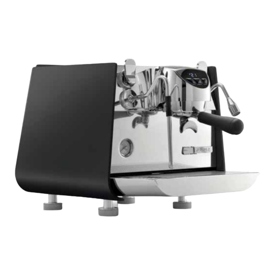
Victoria Arduino Eagle One Prima Service Manual

Victoria Arduino Eagle One Prima Service Manual

Hide thumbs Also See for Eagle One Prima:
Table of Contents

Advertisement

S
S
S
E
E
E
R
R
R
V
V
V
V
IC
C
C
C
E
E
E
E
M
M
M
M
M
M
M
A
A
A
A
A
A
N
N
N
N
N
N
U
U
U
U
U
A
A
A
A
A
A
L
L
L
L

Advertisement

Table of Contents
loading

Summary of Contents for Victoria Arduino Eagle One Prima

  • Page 2 E D I T I O N D AT E M OD I F I CA T I ONS 02/2021 First Edition...
  • Page 3 M A C HI NE D ES C R I PT I O N FI RST I N STA LLA T ION A N D P R EL I M I NA RY O P ER AT I O NS RE MO VA L OF T HE EX TER NA L S U R FA C E I NF US I ON GR O U P S TEA M B O I L E R...
  • Page 5 GENERAL INDEX MA CH I N E DE S CR IP TI ON ....9 MACHINE GEN ERAL D ESCR IP T IO N ..... . . 1 0 SAFETY REGULAT ION S .
  • Page 6 ST EAM BOI L E R ......59 5. 1 R EDU CING STEAM BOILER PRESS U RE ..... 6 1 5.
  • Page 7 EL EC TR IC CO M P ONE NT S ....123 8. 1 CON TROL U N IT ........1 24 8.1.1 CO NT RO L UNIT LEDS .
  • Page 8 D IAGRAMS ......1 79 1 3. 1 H YDRAULIC SCHEME ....... . 1 8 0 1 3.
  • Page 9 MACHINE DESCRIPTION INDEX 01 MA CHINE DESC RIPTION ....9 1 . 1 MACH IN E G E N E RAL D ESCRIPT ION ....10 1.
  • Page 10 M AC H IN E GE N ER AL DE SC RI P T ION Hot water knob Coffee delivery button dose 1 Infusion group Continuous coffee delivery button Hot water wand Coffee delivery button dose 2 Drip tray Filter-holder Steam wand Tank icon Pressure gauge...
  • Page 11 1. 2 SAF ET Y R EG UL AT I ON S Before turning ON the machine make certain that the rating indicated on Read this book carefully. It provides the label matches the available power important information concerning safe- supply.
  • Page 12 The electrician with the apposite qual- The operating temperature must be ification certificate must make sure within the range of [+5, +25]°C. that the section of the system cables is At the end of installation, the device is suitable to the power absorbed by the switched ON and taken to rated oper- machine.
  • Page 13 Simonelli Group is not responsible for In case of breakdown or wrong func- damages caused by failure to comply tioning of the machine, switch it OFF. with this prohibition. Any intervention is strictly forbidden. Contact qualified experts only. During installation, the mains power system needs to be equipped with a Repairs should only be made by the disconnector switch to cut-off each...
  • Page 14 CAUTION WARNING RISK OF POLLUTION RISK OF BURNS OR SCALDING Do not dispose of the machine in the We remind you that before carrying out environment; for the disposal, contact any installation, maintenance, unload- an authorized service centre or contact ing or adjustment operations, the qual- the manufacturer for indications.
  • Page 15 1 . 3 P R EPA RA T I O N B Y WARNING T HE P U R C H A S ER Preparation of the installation site. INFORMATION TO THE USERS The purchaser must prepare the surface Under senses on which the machine will stand suitable Directive 2015/863/EU, con-...
  • Page 16 1.4 SYM BO L S 10 10 General hazard Electrical shock hazard Burns hazard Hazard of damage to the machine Operation reserved for the qualified technician, in compliance with cur- rent standards 1.5 R E S IDU A L R ISK S 11 11 Although the manufacturer has provided mechanical and electrical safety systems,...
  • Page 17 1. 6. 2 M O VE ME NT S Slowly lift the pallet about 30 cm from the ground and reach the loading area. After checking that there are no obstacles, things or people, proceed with the loading. Once you arrive at your destination, always with a suitable lifting device (e.g.
  • Page 18 1 . 7 CO NTE NTS C HE C K Upon receipt of the box, check that the packaging is intact and visually undamaged. Inside the packaging must be the instruction manual and the relative kit. In case of damage or faults, contact your local dealer. For any communication, always communicate the serial number.
  • Page 19: Table Of Contents

    FIRST INSTALLATION AND PRELIMINARY OPERATIONS INDEX 02 FIRST INSTA L L ATION AND PREL IM INARY OPERATIONS ..1 9 2. 1 P OSIT ION IN G ....... . 20 2.
  • Page 20: Po Sitio Ning

    Prior to installation please carefully read the safety instructions in this manual. The RISK OF POLLUTION company cannot be held responsible for damage to persons or property arising from DO NOT DISPOSE PACKAGING in the non-compliance with safety regulations, environment. either during installation or maintenance of the machine described in this manual.
  • Page 21: Te Ch Ni Cal Ch Aracterist Ic

    2 .2 TE CHNIC AL C HAR AC T ERIST I C 220-240 V~ 50-60 Hz 2600 W EL E CTRIC AL DA TA 110 - 120 V~ 50-60 Hz 1800 W 220-240 V~ 50-60 Hz 1800 W (AUS/NZ) STE AM B O IL ER C APAC IT Y N ET W EIGH T kg / lb 36 / 79,37...
  • Page 22: Wa Te R S P E Cif Ica Tio Ns

    2. 3 WATE R SPEC I FI CA T IO N S To t a l h a r d n e ss 50 - 60 Monitoring of water recipe to keep it within Wa t e rl in e 2 - 5 required levels and maintenance of filtra- p re s s u re...
  • Page 23: Wa Ter Su Pp Ly

    2 .5 WA TER SU PP LY NOTE The machine arrives in tank version but it is always supplied with direct connection If it is needed to use it with tank, follow components. the installation procedure in paragraph 2.5.1; otherwise, if the direct connection is preferred, follow the procedures in para- graphs 2.5.2, 2.5.3 and 2.5.4.
  • Page 24: D I Re Ct Co N N E Ct I On Ve R S I O N

    2 . 5.2 DI R EC T C ON NE C TI ON VE R SI O N The machine is always supplied with a 1.5 meters long loading pipe (A) and with a 3/8 inch connection. For the waterline, fitting is straight on one side and with an entrance at 90°...
  • Page 25: D Ir E Ct Co N N E Ct I O N V E R S I O N A N D V I C E -V E R S A

    2. 5. 3 S OFT WAR E S W I T C H FR O M TA NK T O DI R EC T C ON N E C T I ON VE RS I ON A N D VI C E-VE RSA Once having set the machine with the direct connection water, it is needed to per- form the software switch from tank to direct...
  • Page 26: Di R Ec T Wa St E Wa Te R Sy St Em

    2 . 5.4 DI R EC T WA ST E WA TE R SY ST EM The drip tray can collect around 1 litre of waste water. In case it is preferred to use a direct waste water system, proceed as it follows: Connect the supplied waste water pipe to the supplied joint and use a Philips...
  • Page 27: P Roce Du Re Of F Irst P Ow Ering O

    2 .6 PR O C ED UR E O F F IRS T POW ERIN G ON When first powering ON the machine, pro- ceed as it follows: Switch ON the machine from the main switch positioned to the bottom on the right.
  • Page 28 NOTE If any alarm appears on the group display, the machine recognizes that there is a problem. Refer to chapter 10 to know how to proceed. WARNING If the boiler is not completely filled with water, this could damage the coffee boiler heating element.
  • Page 29: Wa T E R Inp U T P R Essuref Or D Ire Ct Con N Ect Io N Versio N

    The pressure of the machine must be set while the coffee is brewing. While coffee is delivered, check with the smartphone app Victoria Arduino E1 that the value reaches 9 bar, the optimum value. In the event that it would be necessary, use the knob located below the machine to make an appropriate adjustment.
  • Page 30: H Ot Wa Te R E C Ono Mi Ser A Djustment

    2. 9 HO T WA TER EC O N OM ISE R A DJ UST MEN T NOTE This operation can be carried out while the machine is turned ON. The hot water mixer serves to adjust the temperature of the water leaving the wand and to optimise system performance.
  • Page 31 REMOVAL OF EXTERNAL SURFACE INDEX 03 REM OVAL OF EX TE RNAL SURFACE ..31 3 . 1 RE MOVA L OF TH E CUP H O LDER SURFACE ..33 3.
  • Page 32 Use gloves to protect against sharp or hot surfaces that you can bump against invol- untarily during operations. DANGER Before proceeding with the operations described in this chapter make sure that the machine is turned OFF and unplugged from the mains. NOTE Before proceeding with the removal of the panels it is advisable to clean...
  • Page 33: Re Mova L Of Th E Cup H O Lder Surface

    3 .1 R EMO VA L O F T H E C UP HO L DER SUR FA CE To remove the cup holder surface: Utilising a Philips screwdriver, remove the 4 screws of the module. Remove the panel.
  • Page 34: Re Mov A L Of Th E Sid E Pa Nels

    3. 2 R E MO VA L O F T HE SIDE PAN EL S The procedure is identical for each side panel. To remove one side panel, it is necessary to: Remove the cup holder surface. Utilising a Philips screwdriver, loosen the screws on the upper part.
  • Page 35: Re Mova L Of Th E Rear P Anel

    3 .3 R EM O VAL O F THE REAR PAN E L To remove the back panel it is necessary to: Remove the cup holder surface. 11 11 Remove both side panels. Utilizing a Philips screwdriver, loosen the two upper screws.
  • Page 36 With a hand pull the high side of the pan- el and with the other hand lift it from the bottom. Disconnect the LED bar before to com- pletely remove the panel.
  • Page 37 3. 3. 1 D IS A SS EM B LE T H E RE AR PA N EL The rear panel of E1 PRIMA can be person- alized. To proceed it is necessary to disassemble it, as it follows. Remove the rear panel as described in the previous paragraph.
  • Page 38: Re Mova L Of Low Er Rea R Panel

    3. 4 R E MO VA L O F L O WE R REAR PAN E L To remove the lower rear panel, it is neces- sary to: Remove the rear panel as described in the previous paragraph. Utilizing a Philips screwdriver, remove the two lateral screws.
  • Page 39: Re Mova L Of Th E Low Er Fro Nt Pa Nel

    Using a 3 mm Allen Key, loosen the three screws to disassemble the panel. NOTE There is a washer between the screw and the panel. 3 .5 R EMO VA L O F T H E L OWE R F RO N T PAN E L To remove the lower front panel, it is necessary to: Remove the cup holder surface and both...
  • Page 40 Utilizing a Philips screwdriver, loosen the two side screws that keep the front panel in position. NOTE Owing to the shape of the panel, it is not necessary to loosen the screws totally. Lower the panel to free it from the fixing screws, rotate it from the top downwards and pull it out.
  • Page 41: Re Mova L Of Th E G Ro Up Cover

    3 .6 R EM O VAL O F 11 11 29 THE GRO UP CO VE R To access the group, proceed as it follows. Remove the side panels, the drip tray and the lower front panel, as described in the previous paragraphs.
  • Page 42 Check connections to memorize them and disconnect them. DANGER If the machine has been turn OFF recently, wear protective gloves. For further information about operations on the group cover and service board, refer to Chapter 8.
  • Page 43 INFUSION GROUP Replace every 4-6 months Replace every 12 months INDEX 04 INFUSION G ROUP ....43 4. 1 RE MOVA L OF SH OWER, PAVILI ON AND SEA L ..4 6 4.
  • Page 44 The infusion group is part of the NEO (New 01 01 Engine Optimization), that guarantees high performance while reducing the energy consumption of the machine. Hence this group is different from common systems with thermosiphon circulation. In fact, the temperature of the group is ensured by the presence of a heating element cartridge.
  • Page 45 The last part of the infusion group is houses a pavilion, a shower and underpan seal. The pavilion distances the shower from the coffee, according to the need for different thicknesses. The machine comes with 3 mm pavilions. The shower is the interface between the coffee and the machine, preventing the coffee from rising inside the machine.
  • Page 46: Infusion G Roup

    4. 1 R E MO VA L O F S HO WER , PAVIL IO N AN D SE AL To remove the shower and pavilion it is suf- ficient to loosen the central screw under the group. To change the seal use an awl or a slim flat- head screwdriver and at first remove one edge of the seal and then remove it entirely.
  • Page 47 PROBLEMS The sensor could not work properly. Example: The light is always orange, as the sen- sor feels the filter holder presence, also in absence of it: sensor in short circuit, needs to be replaced. The light is mostly OFF, and it is ON only with some movement of the filter hold- er.
  • Page 48 Utilizing a 13 mm wrench, loosen the sen- sor fixing nut. Utilizing an adjustable wrench, slide out the sensor. WARNING When the filter holder sensor is rein- serted, make sure it is flush with the inner of the group head and verify the proper functioning.
  • Page 49: Re P La Cin G Th E Seal In Th E Pr E - In F Usion Ch Amber

    4 .3 R EPL AC IN G T HE SEA L IN TH E PR E- I N FU SIO N C HA MB ER The pre-infusion chamber is sealed by a cover fixed with four hex screws. Under the cover there is a seal that should be changed annually, in fact, like all seals, it may deteriorate in time and lose elasticity.
  • Page 50: H E A Ting Ele Me N

    Utilizing a 3 mm Allen key, remove the four screws and open the chamber. 4. 4 HE ATIN G EL EME N T The NEO technology manages temper- atures of the "infusion group and coffee boiler" system, to give a proper extraction water temperature, in accord with what has been set in the programming as MYCOFFEE Temperature.
  • Page 51 4. 4. 1 R EM OVAL OF T H E H EA T I NG EL EME NT The heating element cartridge is accessible from the rear wall that holds the infusion group. To remove it, proceed as it follows. Remove the cup holder surface, the side panels, the drip tray, the lower front pan- el and the group cover, as explained in...
  • Page 52 Utilizing a Philips screwdriver, loosen the screw that block the heating element. Pull out the heating element.
  • Page 53: Te Mper At U Re Pr Ob E

    4 .5 TE MPER AT U RE PR OB E The temperature probe of the infusion group permits to the control unit to know the cur- rent temperature of the group. Typical values of the temperature probe are approximately 1,1 kOhm at 25°C (room temperature) and approximately 1.4 kOhm at 90°C.
  • Page 54: R E Mo V Al O F T H E T E Mp E R A T U R E P R O Be

    4 . 5.1 R EM O VA L OF TH E TE M P E R A TU RE P ROB E To remove the temperature probe it's nec- essary to: Remove the group cover, as described in Chapter 3. Disconnect the temperature probe from 31 31 the central unit.
  • Page 55: H Ig H- Lim It Th E Rmost At

    4 .6 HIGH - L IM IT T HE RM OSTA T S The high-limit thermostats are connect- ed in series with the heating element and opens the electrical circuit once the tem- perature limit of 135°C in the infusion group has been exceeded.
  • Page 56: C Off E E Valve

    4. 7 COF FE E VALV E The infusion group is provided with a three- way valve called coffee valve. It's a solenoid valve that is normally closed and opens when it receives a command to dispense coffee. When this valve is closed, the liquid remain- ing in the group is pushed by pressure towards the third outlet of valve, that is con- nected to the exhaust manifold.
  • Page 57 Remove the side panels, the drip tray, the lower front panel and the group cover, as explained in Chapter 3. Utilizing plier, remove the clip keeping the Teflon pipe of the third outlet. Disconnect the Teflon pipe of the third outlet.
  • Page 58 Utilizing a Philips screwdriver, remove the head screw. Place a cloth or absorbent paper under- neath the valve and, utilising a 3 mm Al- len key, remove the two screws that fix the body to the group. Remove the body of the valve. Check the contact points that often can be full of limescale.
  • Page 59 STEAM BOILER Replace every 12 months INDEX 05 STEA M B OIL E R ..... 59 5 .1 RE DU CIN G STE AM BO ILER PRESSURE ....6 1 5 .
  • Page 60 The E1 PRIMA is provided by a Stainless- 01 01 Steel boiler of 1,5 l. It is covered by thermal insulation to prevent heat dispersion and it is equipped with the following parts. On the top: An anti-suction valve, to ensure that air enters the boiler during the ma- chine cooling phase.
  • Page 61: Stea M B Oil E R

    5 .1 R EDUC IN G ST E AM B O ILER PR ESSURE Before to work on steam boiler and relative parts, it is mandatory to reduce its inner pressure. The E1 PRIMA, compared to the other tra- ditional machines, does not have manual steam lever, but electronic one.
  • Page 62: R Em Ova L Of T He St Eam Bo Iler

    5. 3 R E MO VA L O F T HE STEA M B OI LE R To remove the steam boiler, proceed as follow: Remove the cup holder surface and the left side panel, as described in Chapter 3. Disconnect the level probe.
  • Page 63 Remove the safety valve. Utilizing a 17 mm wrench, disconnect the pressure sensor pipe. Utilizing a 17 mm wrench, disconnect the hot water pipe. Utilizing a 17 mm wrench, disconnect the inlet pipe.
  • Page 64 Rotate the machine on the right side, be- ing careful to not damage it. Utilizing a Philips screwdriver, remove the 17 17 two screws that keep the base cover. Disconnect the five electrical cables, cor- responding to: thermal fuse, heating ele- ment and mass.
  • Page 65 Utilizing a 10 mm wrench, remove the two nuts. Remove the steam boiler, lifting it up- wards and turning it clockwise.
  • Page 66: Te St T H E H E A T I Ng E Lem Ent

    5. 4 HE ATIN G EL EME N T The 1600 W heating element is removable and it is accessible from the bottom of the machine. 5 . 4.1 TE ST T H E H E A T I NG E LEM ENT To test the heating element, proceed as it follows: Rotate the machine on the right side, be-...
  • Page 67 5. 4. 2 R EM OV E T HE H EAT I N G E LEME NT To remove the heating element, proceed as it follows: Remove the steam boiler, as described in paragraph 5.3. Remove the safety thermo-fuse. Utilizing a 10 mm wrench, remove the three nuts.
  • Page 68: T He Saf E Ty T He Rmo - F Use

    NOTE Each time you replace the heating ele- ment is also necessary to change the viton O-ring that isolates it from the boiler because it is a part subject to wear, therefore the component must be ordered together with the heating element.
  • Page 69 Disconnect the safety thermo-fuse. Utilizing a tester, check the continuity of the safety thermo-fuse. If there is not continuity, change the safety thermo-fuse.
  • Page 70: The L E Ve L P Robe

    5. 6 T HE L E VEL PR OB E The water inside the steam boiler is main- tained at a constant level through the use of a level probe inserted inside the boiler. This probe is connected to the electronic control unit that continuously polls the probe.
  • Page 71: A N Ti -Suct Ion Valve

    5 .7 A NTI- SUC T IO N VALVE The anti-suction valve ensures that air enters the heater during the machine cool- ing phase. In this way the reduction of water volume due to cooling does not create decompressions that may give rise to drawbacks such as the suction of milk through the steam wand.
  • Page 72: Sa Fe Ty Valve

    5. 8 SA FE TY VALVE The steam safety valve is made to open at the pressure of 3 bar. WHEN TO REPLACE For safety reasons each time the valve comes into operation it should be replaced to ensure perfect operation. So if the heater floods or there is excess steam it is necessary to secure the machine by replacing the entire valve.
  • Page 73 COFFEE BOILER Replace every 12 months INDEX 06 COFF EE B OIL ER ....73 6. 1 RE MOVA L OF TH E COF FEE BOILER ....7 5 6 .
  • Page 74 E1 PRIMA provides for the group a Stainless- Steel coffee boiler of 0.14 litre. The coffee boiler is part of the NEO (New Engine Optimization), that guarantees high performance while reducing the energy consumption of the machine. It is covered by thermal insulation to pre- vent heat dispersion.
  • Page 75: Coffee Boiler

    6 .1 R EM O VAL O F THE C O FF EE B OIL ER WARNING The coffee boiler contains just 0.14 litre of water, therefore it is not necessary to empty it when it is needed to remove it or its components.
  • Page 76 Remove the 4 screws that hold the con- trol unit support. Remove the control unit support and, if preferred, disconnect the cables to sim- plify the operations. Extract the temperature probe cable and, if necessary, cut the clamps. Utilizing a 12 mm and 13 mm wrenches, unscrew and remove the temperature probe.
  • Page 77 Remove the 4 screws of the water tank 11 11 support. Extract the water tank support and place it on the machine. Disconnect the two heating element ca- bles from the bottom of the coffee boiler. Utilizing a 13 mm wrench by entering from the right side of the machine, and keep- ing the coffee boiler with the other hand, unscrew the inlet coffee boiler pipe.
  • Page 78 Reposition the water tank support. Utilizing a 17 mm wrench, remove the safety valve of the steam boiler. Utilizing a 17 mm wrench and keeping the 17 17 coffee boiler, unscrew the outlet pipe to the group. Cut the clamp of the expansion valve and extract the pipe.
  • Page 79: H Ea Ti Ng E Le Me N

    6 .2 HEA TIN G EL EME N T The NEO technology manages tempera- tures of the "infusion group and coffee boil- er" system, to give a proper extraction water temperature, in accord with what has been set in the programming as MYCOFFEE tem- perature.
  • Page 80 To remove the heating element, it is neces- sary to: Secure the coffee boiler to a vice. Using a 26 mm wrench, remove the heat- ing element. NOTE When replacing the heating element, it is mandatory to utilize a new O-ring. WARNING After replacing the coffee boiler, pro- ceed with restoring water inside the...
  • Page 81: Te Mp E Ra T Ure P Robe

    6 .3 TE MPER AT U RE PR OB E The temperature probe of the coffee boiler permits to the control unit to know the cur- rent temperature of the coffee boiler. Typical values of the temperature probe are approximately 40 kOhm at about 25°C (room temperature) and 5 kOhm at about 90°C.
  • Page 82 6 . 3.1 R EM O VA L OF TH E TE M P E R A TU RE P ROB E WARNING If the machine is hot, reduce the inner pressure of the coffee boiler, as explained in paragraph 4.7.1. To remove the temperature probe, proceed as it follows: Remove the cup holder surface and the...
  • Page 83 Remove the control unit support and, if preferred, disconnect the cables to sim- plify the operations. Extract the temperature probe cable and, 31 31 if necessary, cut the clamps. Utilizing a 12 mm and 13 mm wrenches, remove the temperature probe. Remove calcification with...
  • Page 84: H Ig H- Lim It Th E Rmost At

    6. 4 HIG H-L IM IT THE RMO STAT S The high-limit thermostats are connected in series with the heating element and open the electrical circuit once the temperature limit of 135°C in the coffee boiler has been exceeded. If the heating element does not turn ON, check the continuity of the high-limit ther- mostats.
  • Page 85 Utilizing a 14 mm wrench and a plier, re- move the valve. NOTE When replacing the expansion valve, wrap its threading with Teflon tape or use liquid Loctite to prevent leakage.
  • Page 86: P R Oce Du Re F Or

    6. 6 P R OC E DUR E FO R A U TO MA TIC AL LY FI LL IN G T HE C OF FEE BO IL ER Once the various parts of the coffee boiler, or the boiler itself, have been replaced, it is necessary to carefully fill it to prevent it from starting to heat in the absence of water.
  • Page 87 HYDRAULIC CIRCUIT INDEX 0 7 HYD RAULI C CIR CUIT ....87 7. 1 E X HAU ST MA N IF OLD A ND DRA IN BO X ... . . 8 8 7 .
  • Page 88 The hydraulic circuit of the E1 PRIMA fol- 01 01 lows a new technology: NEO (New Engine Optimization). The NEO engine uses an instant heating system allowing only the necessary amount of water for the extraction. To be heated, thus using less amount of water and boiler optimization.
  • Page 89 7. 2 TA NK The tank is easily removable by hand and it is reachable by opening the tank cover on the cup holder surface. It can contain up to 1.5 lt of water. It does not contain any float, since a capacitive sensor, placed on the external surface of the tank container, can feel the water presence inside the tank.
  • Page 90 Disconnect the cables from the tank valve. Utilizing a small screwdriver, unscrew the two screws that fix the valve to the frame. Utilizing a plier, remove the clip and the Teflon pipe of the third outlet. Utilizing a vise and a 14 mm wrench, un- screw the nut and remove the coil of the valve.
  • Page 91 7 . 3.2 R EM O VAL OF T H E WA TE R ST OP VALVE To remove the water stop valve, proceed as it follows: Close the water mains. Remove the cup holder surface, the side 11 11 panels, the rear panel and the rear lower panel as described in Chapter 3.
  • Page 92 Remove the electrical cables. Utilizing a flat screwdriver, push the black ring and extract the pipe. Extract the valve.
  • Page 93 7. 4 TH E PUMP IN G EL EME NT The pump is located on the left side of the machine. The duration of the pump depends on the amount of daily work and the quality of the water. The machine pres- sure set by the factory is ideal for the extraction of the coffee: 9 bar.
  • Page 94 Rotate the machine on the right side, be- ing careful to not damage it. Completely unscrew and remove the pressure control wheel. NOTE Notice that the pressure control wheel contains a spring. Utilizing a 7 mm wrench, remove the four nuts and washers that fix the pump-mo- tor assembly to the frame.
  • Page 95 Utilizing a 12 mm wrench, remove the inlet and outgoing Teflon pipes of the pump. Utilizing a Philips screwdriver, remove the three screws that fix the static relay bracket. Remove the static relay bracket. NOTE If it is necessary, disconnect some cables.
  • Page 96 Once the pump-motor assembly has been removed, to replace the pump proceed as it follows: Utilizing a 14 mm wrench, remove the inlet fitting of the pump. Utilizing a 12 mm wrench, remove the Tef- lon pipe. Utilizing a 9 mm wrench, remove the T outgoing fitting of the pump.
  • Page 97 7 . 4.2 R EM O VAL OF T H E CO NDE NSE R Once the pump-motor assembly has been removed and the condenser needs to be replaced, proceed as it follows: Disconnect the cables from the condens- Utilizing a 13 mm wrench, remove the condenser.
  • Page 98 7 . 5 RE MO VA L O F T HE A UTO - F ILL VA LV E The auto-fill valve is positioned on the left side of the machine, over the pumps. Its operation regulates the amount of water that flows inside the heater during all phas- es of machine operation.
  • Page 99 Utilizing a 13 mm and a 12 mm wrench- es, disconnect the inlet pipe from the au- to-fill valve. Utilizing a Philips screwdriver, unscrew the two screws. Extract the auto-fill valve from the upper side and disconnect the cables.
  • Page 100 7 . 6 FL O W ME TER AN D N O T R E TUR N VALV E To set the coffee dose, the machine has a flowmeter, also called fan. It is located on front-right side of the machine.
  • Page 101 HOW TO VERIFY THE SIGNAL OF THE FLOWMETER To measure the signal it is necessary to access to the control unit located on the right side. Remove the right side panel as shown in Chapter 3. With a tester measure the voltage al- ternating between the ends of the faulty flowmeter (see figure).
  • Page 102 Utilizing a 14 mm and 17 mm wrenches, remove the outgoing pipe from the flow- meter. Utilizing a 12 mm and 13 mm wrenches, remove the not return valve. Utilizing two 17 mm wrenches, remove the inlet pipe from the flowmeter. Utilizing a small Philips screwdriver, re- move the two screws that keep the flow- meter on the bracket.
  • Page 103 The flowmeter is made of various parts, as shown in the picture. It is good practice to substitute the gaskets each time it is completely inspected. Check that there is no limestone in the fan input grid, unscrew the three screws that hold the cover and check that there is nothing to obstruct the regular operation.
  • Page 104 7 . 6. 2 R EM O VA L OF TH E PRE I N FU SI O N RE ST RI CT OR Attention must be given to the restrictor at the exit from the flowmeter. It is called pre-infusion restrictor, since its size effects the pre-infusion time: bigger is the size, shorter is the pre-infusion.
  • Page 105 7. 7 H OT AN D CO LD WAT ER VALV E The E1 PRIMA is provided with a cold water valve with adjustable mixer. In this way the outlet water temperature can be lowered by mixing hot water from the boiler with cold water from the network, thus reducing the levy in the boiler and consequently saving on heating.
  • Page 106 Position the tip at the point shown in the figure during delivery, considering that the hot water and cold water valves are parallel, simply verify the operation of this relay to check both valves. 7.7 . 1 RE M O VA L OF TH E HO T WA T E R VALVE To remove the hot water valve, it is nec- essary to extract both hot and cold water...
  • Page 107 Utilizing a 13 mm wrench, remove the outgoing pipe from the hot and cold wa- ter valves. Utilizing two 17 mm wrenches, remove the inlet pipe from the cold water valve. Utilizing a Philips screwdriver, remove the two screws that keep the hot water valve. Extract the valves from the upper side and disconnect the cables.
  • Page 108 To check the hot water valve: Utilizing a 14 mm wrench, unscrew the nut and remove the coil of the valve. Utilizing a 14 mm wrench, unscrew the valve base. Check that the spring is working properly and that the inner cylinder is clean. NOTE If there is nothing visible that affects its use, replace the valve completely.
  • Page 109 To replace the hot water valve: Utilizing a vise and a 10 mm wrench, di- vide the hot and cold water valves. NOTE When reassembling the valves, use Loctite glue in the fitting. 7 . 7 .2 R EM OVA L OF T H E CO LD WA T ER VALVE To remove the cold water valve follow the first 10 steps of the previous paragraph.
  • Page 110 7 . 8 ST EA M VA LVE The E1 PRIMA is not provided with a mechan- ical steam tap controlled by a manual NOTE lever, but with a three-way solenoid valve controlled electronically. This will reduce the The same steam valve, in the same needed maintenance to maintain a con- position, is used for the Easycream stant functioning of the steam service.
  • Page 111 Turn the machine OFF. Remove the cup holder surface. The steam valve (A) is located on the right side, between the tank and the coffee boiler. Utilizing a 14 mm and 17 mm wrenches, remove the incoming copper pipe from the boiler.
  • Page 112 Extract the valve and disconnect the ca- bles. Cut the clamp and remove the Teflon pipe of the third outlet. Utilizing a 13 mm wrench, unscrew the nut and remove the coil of the valve. Utilizing a vise and a 16 mm wrench, un- screw the valve base.
  • Page 113 Check that the spring is working properly and that the inner cylinder is clean. If the replacement of the valve body is necessary, utilize a 14 mm and 16 mm wrenches to disassemble the valve. NOTE If there is nothing visible that affects its use, replace the valve completely.
  • Page 114 7 . 9 ST EA M , HO T WA T ER AN D E A SY CR EAM (O PT I ON A L ) WAN DS All wands are composed of a joint, a junc- tion and a nozzle. These parts are equipped with o-rings to avoid leaks.
  • Page 115 Using plier and cloth or paper to avoid damage, or simply by hand, unscrew the final part of the nozzle. Utilizing a 9 mm wrench, block the upper part of the wand and, by hand, unscrew the middle part of the nozzle. Utilizing a 24 mm wrench and a 20 mm one, block the front fitting and unscrew the copper pipe.
  • Page 116 Utilizing a 3 mm Allen key, remove the two screws keeping the joint of the wand. Utilizing a 24 mm wrench or simply by hand, remove the fitting. The junction is visible now, with its spring. Notice that there is a white Teflon o-ring inside the joint.
  • Page 117 NOTE To remove the Easycream wand, it is necessary to disconnect the tempera- ture probe wire too. NOTE The final part of the hot water wand includes the water diffuser head. It can be needed to clean it if the water flow is not regular.
  • Page 118 7 . 1 0 EA SY CR EAM (O P T ION AL ) The E1 PRIMA is also available with the Easycream system, which allows the baris- ta to obtain a dense, velvety milk cream quickly and automatically. Easycream is composed by a steam wand and a temperature probe.
  • Page 119 This operation is carried out with the machine switched ON so as to perfectly fine tune the air valve. To set the Easycream, proceed as it follows. Utilizing the Victoria Arduino E1 App, in the programming of the MACHINE SET- TING, enable Easycream and save.
  • Page 120 Utilizing the Victoria Arduino E1 App, in the programming of the MYCOFFEE rec- ipe, set the Easycream parameters and save. NOTE There are two different settings for the Easycream, since Easycream button can be pushed up (Key 1) or down (Key 2) to have two different Easycream rec- ipes.
  • Page 121 7. 1 1 R E MO VAL O F THE PR ES SURE G AU G E The E1 PRIMA is provided with a pressure gauge that permits to read the steam boiler pressure. To remove it, proceed as it follows: Lower the steam boiler pressure by fol- lowing the procedure described in para- graph 5.1.
  • Page 122 Utilizing a 12 mm and a 13 mm wrenches, block the pressure gauge and loosen the nut. Utilizing a 13 mm wrench, keep the nut and loosen the pressure gauge by hand.
  • Page 123 ELECTRIC COMPONENTS INDEX 08 ELECTRI C COMPONE NTS ....1 23 8. 1 CONTROL U N IT ......12 4 8 .
  • Page 124: Co N T Ro L U N I T L E

    WARNING Before proceeding with the operations described in this chapter, make sure that the machine is turned OFF and unplugged from the mains. 8. 1 CON TRO L UN I T To access the control unit it is necessary to remove the cup holder surface and the right side panel, as described in Chapter 3.
  • Page 125 FOCUS ON THE VARIOUS PARTS Battery and fuses: 2 Ampere fuse: low power IN (+24VDC) fuse. 6.3 Ampere fuse: power IN (+230VAC) fuse to solenoid valves, pump and contactor. 6.3 Ampere fuse: power IN (+230VAC) fuse to coffee boiler's and group's heating elements. CR1220 3 Volt battery: to store date and time.
  • Page 126 Lower side, “low voltage”: Temperature probes, see details below. Presence sensors, see details below. Pressure transducers, see details below. none. CN16 none. CN17 DIP switch: all to OFF, used only by the manufacturer. In details, regarding to temperature probes: 10 10 coffee boiler temperature probe.
  • Page 127 Right side, “high voltage”: power IN (+230VAC). CN18 10 pins green terminal for pump, CN19 contactor and solenoid valves, see details below. static relay. coffee group’s heating element. coffee boiler’s heating element. In details, regarding to CN19, the 10 pins green terminal: CABLE COLOUR DESCRIPTION...
  • Page 128 8 . 1.1 CO N T RO L U NI T LED S The control unit contains LEDs, useful to recognize the functioning of parts of the machine. There is a writing next to each LED to indi- cate what it refers to. For example, the focus on the picture shows the writing SH, that indicates the activation of the static relay.
  • Page 129 8 .2 C ONTAC T O R 17 17 The contactor (A) is placed on the rear side of the machine, so it possible to access it by removing the rear panel, as described in chapter 3. It is a relay that enables the heating phase of the machine.
  • Page 130 8. 3 STA TIC R EL AY The static relay (B) is placed on the rear side of the machine above the contactor, so it possible to access it by removing the rear panel, as described in chapter 3. It controls the heating element of the steam boiler.
  • Page 131 REPLACEMENT To replace the static relay, proceed as it fol- lows: Utilizing a Philips screwdriver, remove the right screw. Utilizing a Philips screwdriver, loosen the left screw and pull out the static relay. Utilizing a Philips screwdriver, loosen the four screws and remove the cables. 8 .4 TR ANSF ORM ER The machine provides VDC to the control unit and to some components thanks to a...
  • Page 132 Looking at the connections the visible parts are: Outputs Inputs The outputs are connected to the control unit on CN20, as explained in paragraph 8.1. REPLACEMENT If the outputs do not give +24VDC the trans- former is broken. In this case the control unit and the ma- chine will appear completely OFF.
  • Page 133: P Re Ssu Re Tr An Sducers

    The cable of the steam boiler pressure transducer has a red label to recognise If the pressure in the smartphone app Victoria Arduino E1 is unshown or certain- ly wrong, check the cabling or replace the proper pressure transducer. 8.5. 1 R EM OVA L OF T HE WAT ER...
  • Page 134: The Steam Boiler Pressure Transducer

    Unscrew and remove the pressure trans- ducer by hand. 8 . 5.2 REMOVAL OF THE STEAM BOILER PRESSURE TRANSDUCER The steam boiler pressure transducer is placed on the front of the machine, over the pressure gauge. To remove it, proceed as it follows: Remove the cup holder surface, the side panels, the drip tray and the lower front panel, as described in chapter 3.
  • Page 135 8 .6 GRO UP C OV ER A ND SERV IC E B O AR D The coffee group has a cover, where the service board is installed. To access it, remove the group cover as described in paragraph 3.6. The service board includes, on the front side: The ghost display...
  • Page 136 NOTE It is possible to check the functioning of all segments and icons of the ghost display. Press and hold together the 3-buttons of the keypad. NOTE Hold the 3-buttons for a maximum of 2 seconds, otherwise the EMPTY BOILER procedure will start, as explained in paragraph 9.4.2.
  • Page 137 8 .7 SERVIC E K N OB Steam / Easycream and hot water wands have their knob to start their service. It is possible to push the knob up and down, to have two different doses, in accord with the programming. If any knob is not working, check the cabling or replace it, as it follows: Remove the cup holder surface, as de-...
  • Page 138: Wa T E R Tan K P Re Sence Senso R

    8. 8 WATE R TANK P RE SE N CE SE NSO R The water tank presence sensor is a capac- itive sensor that recognises the presence of water in the tank. If it does not work, check its connection and replace it if needed.
  • Page 139: L Igh T

    Disconnect the cabling. 8 .9 L IGHTS The E1 PRIMA is equipped with lights: a LED on each side of the coffee group and a LED bar on the back side of the machine. All lights are connected with the same cabling in parallel to the control unit.
  • Page 140 To replace the LED bar on the back side, proceed as it follows: Remove the rear panel, as described in chapter 3. Cut the clamp of the wire. Utilizing a 5,5 mm wrench, remove the two nuts fixing the bar.
  • Page 141 PROGRAMMING INDEX 09 PROGRAMMING ....14 1 9 . 1 BASIC FUN CTION S ......14 2 9.
  • Page 142 NOTE Please note that the programming could vary from certain firmware release on. This Service Manual is based on firm- ware release v32. The group buttons and icons are identified as 1A, 1B, 1C, T and H, as shown in the picture. Tank icon Ghost display Heating icon...
  • Page 143 9. 1. 3 S W I T C HI N G FROM TAN K T O DI REC T C ONN EC T I ON To switch from tank to direct connection, proceed as it follows: Turn OFF the machine using the main switch.
  • Page 144 9. 2 P R OGR A MMIN G The E1 PRIMA is completely programmable by the Victoria Arduino APP, which can be downloaded from the ANDROID/IOS store respectively. A basic programming is also possible from the keyboard on the machine with the group buttons (1A, 1B, 1C) and will be explained in the next paragraphs.
  • Page 145 9. 2. 1 C OFFE E T EMP ERA TU RE 10 10 To program coffee temperature, proceed as it follows: Press and hold the 1A and 1C buttons for 5 seconds, to enter the first level program- ming menu. Access is confirmed when the 1B button 11 11 starts blinking and the set temperature is...
  • Page 146 9 . 2.2 CO FFE E DOS E S To program coffee doses, proceed as it fol- lows: Press and hold the 1A and 1C buttons for 5 seconds, to enter the first level program- ming menu. Access is confirmed when the 1B button starts blinking and the set temperature is shown on the display.
  • Page 147 Press the desired coffee button to initiate 18 18 delivery. The pressed button remains lit and the delivery time (in seconds) is shown on the display. Press the coffee button again to stop de- livery and store the dose in the memory. To confirm and exit, press the 1B button twice.
  • Page 148 9 . 2.3 HO T WA T ER D OS ES To program the final hot water tempera- ture, proceed as follows: Press and hold the 1A and 1C buttons for 5 seconds, to enter the first level program- ming menu. Access is confirmed when the 1B button starts blinking and the set temperature is shown on the display.
  • Page 149 Programming takes place by operating the lever. Push the upper part of the lever to programme the first dose of hot water "key 1". Push the lower part of the lever to programme the second dose of hot wa- ter "key 2". Push the lever again to stop delivery and store the dose in the memory.
  • Page 150 9 . 2.4 E A S YCR EA M T EM PE RAT UR E (O P T IO N A L) To program the Easycream final tempera- ture: Press and hold the 1A and 1C buttons for 5 seconds, to enter the first level program- ming menu.
  • Page 151 Programming takes place by operating the lever. Push the upper part of the lever to enter the final temperature program- ming of the first Easycream recipe "key 1". Push the lower part of the lever to enter the final temperature programming of the second Easycream recipe "key 2".
  • Page 152 Replace the filter in the filter holder with a blind filter. Place the manufacturer’s recommended dose of specific powder detergent inside and put the filter holder into the group. Press and hold the 1A and 1C buttons for 5 seconds to enter the first level program- ming menu.
  • Page 153 Press the 1B button to enter the second 41 41 level programming menu. Access is confirmed when the message “dS” is shown on the display and the 1B button flashes. Press the 1B button to enter the third level programming menu. Access is confirmed when the message “cL”...
  • Page 154 Press the 1C button to start the wash cy- cle; the button flashes rapidly. Once the washing phase is complete, the machine stops and the 1C button re- mains ON. NOTE Before rinsing, remove any residual detergent remaining in the filter holder. Press the 1C button to start the rinse phase;...
  • Page 155 9 .4 SPEC IAL F UN C T IO N S 9. 4. 1 G HOS T DI SP LA Y V ERI FI C A T IO N P ROC E DURE To verify the correct functioning of all the segments and icons of the ghost display, proceed as it follows: Press and hold together the 1A, 1B and 1C...
  • Page 156 The 1A, 1B and 1C buttons keypad will be fixed and a 3 seconds countdown will ap- pear on the ghost display. At the end of the countdown, the procedure will auto- matically starts. WARNING Keep attention to the steam and hot water coming out from the machine.
  • Page 157 Writing “FI” appears on the ghost display and the 1A, 1B and 1C buttons flash fast. Wait until the 1A, 1B and 1C buttons flash more slowly. Press and hold the 1A and 1C buttons to- gether until procedure is engaged (the pump starts to run).
  • Page 158 Press and hold the 1B and 1C buttons 61 61 while turning the machine ON using the main switch. The writing “’dC” appears on the ghost display and the 1B and 1C buttons flash. Switch the machine OFF to record the changings.
  • Page 159 Press and hold the 1A and 1B buttons while turning the machine ON using the main switch. The writing “’dP” appears on the ghost display; the 1A, 1B and 1C buttons are steady ON and the H icon flashes. Switch the machine OFF to record the changings.
  • Page 160 9. 5 M A CH INE UPD AT E The software version of E1 PRIMA is only vis- ible in Victoria Arduino E1 APP. If an update is needed for any reasons, pro- ceed as it follows: Format a USB 1.0 or 2.0 stick as FAT32/4096 bytes.
  • Page 161 As the file loads, the rear led bar blinks, the writtens “Pr” and then “US” appear on the group display and the buttons start flashing until the machine returns to Stand-by mode. Switch the machine OFF and remove the USB stick. Switch the machine ON and do the RESET PARAMETERS procedure as described in paragraph 9.4.5.
  • Page 163 ALARMS AND CONTROL OF THE EMERGENCIES INDEX 1 0 AL AR MS A N D CONT RO L O F TH E EME RG EN C I ES . . . 1 6 3 1 0. 1 ALA RMS AN D SOLUTIO NS ....16 4...
  • Page 164 The E1 PRIMA can alert the user with various “alarms” on the group display and by key- pad and icons signalling. Below is a Key to decoding the various alarms and signals. To follow the suggested solutions, if needed, refer to the relative chapters in this manual. NOTE Some alarms are significant only from certain firmware release on.
  • Page 165 MAI N KEYPA D AL A R M S OL U T I ON S REA SO N SIG N AL L I N G Switch the machine OFF and ON to restart the auto-fill function. If not solved: • check proper flow of inlet water from the mains or from the tank;...
  • Page 166 MAI N K EYPA D A L A R M SO L U T I ON S R EASO N S IG NA LLI NG On the level probe: The control unit cannot • check the presence of limescale; sense the water level in •...
  • Page 167 MAI N KEYPA D AL A R M S OL U T I ON S REA SO N SIG N AL L I N G Check if the error disappears by switching the machine OFF and ON. If not: • reset all machine parameters General error on with the RESET PARAMETERS pro-...
  • Page 169 MAINTENANCE CHECK LIST INDEX 11 MA INTENANCE CH ECK L IST ... . 1 69 1 1. 1 SIX (6 ) M ON T H S OR 500 00 C Y CLE S MAINT ENANCE ....1 7 0 11.2 TWE LVE ( 12 ) MON TH S O R 10 000 0 C Y CLE S MAINT ENANCE .
  • Page 170 1 1. 1 SI X (6 ) MO N T HS OR 5 0 0 0 0 CYCLE S MA I NTEN A NC E Approximate time for service is 1 hour uninterrupted. Consider that the technicians per- forming the service are aware of safety measures before commencing in regards to iso- lating power, pressure of steam and pressure of water.
  • Page 171 11 .2 TW ELVE (1 2 ) MO N T H S OR 1 0 0 0 0 0 C Y C L ES M A I NT ENA NC E Approximate time for service is 2 hours uninterrupted. Consider that the technicians per- forming the service are aware of safety measures before commencing in regards to iso- lating power, pressure of steam and pressure of water.
  • Page 172 1 1. 3 ON E ( 1) Y EAR MAI N T EN AN CE KI T CHANGE EVERY 4-6 MONTHS CHANGE EVERY 12 MONTHS...
  • Page 173 TROUBLESHOOTING INDEX 12 TROUBL ESHOOT ING ....1 73 1 2.1 COF FE E D OSA G E ERROR ..... . 17 4 1 2.2 BOILE R FILLIN G T IME O UT .
  • Page 174 1 2 .1 CO FF E E DO SAG E E RR OR...
  • Page 175 12 .2 BOIL ER F IL LI N G T IM E OU T...
  • Page 176 1 2 .3 H EA TING TIM EO UT 12.3. 1 S T EA M BOI LER HE AT I NG E RR OR...
  • Page 177 12 .3.2 C O FFE E B OI LE R HE AT I N G ERR OR...
  • Page 178 12.3. 3 CO FFE E GROUP H EA T I NG E RR OR...
  • Page 179 DIAGRAMS INDEX 13 D IAGRAM S ..... . . 179 1 3. 1 HY DR AU LIC SCH E ME ......1 8 0 1 3.
  • Page 180 1 3 .1 H YDR A UL IC SC HEM E...
  • Page 181 POSITION DESCRIPTION Water tank Water tank electrovalve Pump 10 bar - 70 l/h - 170 W Water mains inlet Check valve Water mains inlet electrovalve Flowmeter Calibrated orifice Coffee boiler 0.14 l - 600 W Pouring group electrovalve Filter holder outlet Discharge outlet Safety valve 16,5 bar Anti-vacuum valve...
  • Page 182 1 3 .2 23 0V EL EC TRI CA L D IA G RAM...
  • Page 183 POSITION DESCRIPTION Steam boiler heating element (1600 W) Steam boiler temperature probe Compressor LED strip Left LED spotlight Right LED spotlight Volumetric counter Filter holder presence sensor Water tank presence sensor Control unit Keyboard flat Hot water pressure transducer Steam boiler pressure transducer Pouring group temperature probe Easycream temperature probe Pouring group heating element (300 W)
  • Page 184 1 3 .3 11 0V EL E CTR IC AL DI AG RA M...
  • Page 185 POSITION DESCRIPTION Steam boiler heating element (1600 W) Steam boiler temperature probe Compressor LED strip Left LED spotlight Right LED spotlight Volumetric counter Filter holder presence sensor Water tank presence sensor Control unit Keyboard flat Hot water pressure transducer Steam boiler pressure transducer Pouring group temperature probe Easycream temperature probe Pouring group heating element (300 W)
  • Page 186 1 3 .4 B OIL E R DIAGRA M PROJECT DATA FOR DIRECTIVE PED 97/23/CE VOLUMES 1,5 l 139°C P.V.S. 2.5 Bar 4 Bar FLUID Q.TY PART NUMBER DESCRIPTION MATERIAL 98031201 Lower flange INOX AISI 316L 98031201 Boiler body INOX AISI 316L 98031201 Upper flange INOX...
  • Page 187 SPARE PARTS Update to 01-2021 INDEX 14 SPA RE PA RTS ..... . 1 87 1 4. 1 CABIN E T P ART S ......1 8 8 1 4.
  • Page 188 1 4 .1 CAB INE T PART S NOTE * Specify colour. CODE DESCRIPTION END VALIDITY 0 0 0000011 S/S KNURLED WASHER M4 UNI8842/A 00000060 GALVANIC MEDIUM NUT AQ M3 00000098 CAGE NUT M4 T424 - THICKNESS 1,7-2,3 00000220 S/S SOCKET SCREW M4x45 FULLY THREADED...
  • Page 189 REAR INFERIOR PROFILE WHITE 03003861.NOV REAR INFERIOR PROFILE MATT BLACK 03003871 FRONTAL PANEL 1GR EAGLE ONE CHROMED ALUMINIUM 03003890 FRONT SIDE LOGO EAGLE ONE PRIMA 03003911 INFERIOR FRONT PLATE 1GR EAGLE ONE 03003915 DRIP TRAY 1GR 03003921 MESH WORKTOP 1GR EAGLE ONE...
  • Page 190: Control P An E L Parts

    1 4 .2 CON TRO L PAN EL PART S...
  • Page 191 CODE DESCRIPTION END VALIDITY 0 0 0000113 S/S CROSS HEAD CAP SCREW M4x6 7985 00000165 S/S SCREW M3x8 TCEI ISO 4762 04901501 DISPENSING BOARD 04901520 ELECTRONIC CONTROL BOARD W/ STEAM LEVER MAT 06100300 GROUP COVER EAGLE ONE CHROME 06100304 STEAM LEVER EAGLE ONE 06100306 LEVER SUPPORT EAGLE ONE 07300784...
  • Page 192: P Ou Ring G R Oup Parts

    1 4 .3 P OUR ING GRO UP PA RT S NOTE * Specify version.
  • Page 193 CODE DESCRIPTION END VALIDITY 0 0 0000048 SELF-TAPPING SCREW 2.9x4.5 TC/T.CR. 00000089 S/S CROSS HEAD CAP SCREW M4x12 DIN7985 00000113 S/S CROSS HEAD CAP SCREW M4x6 7985 00000118 S/S HEX SOCKET CAP SCREW M4x12 5931 00000160 S/S WASHER D4X12 UNI 6593 00000168 S/S HEXAGON SOCKET HEAD SCREW M6x35 UNI 5931 00000197...
  • Page 194 1 4 .4 H YDR A UL IC PART S NOTE ** North America Market.
  • Page 195 CODE DESCRIPTION END VALIDITY 0 0 0000011 S/S KNURLED WASHER M4 UNI8842/A 00000113 S/S CROSS HEAD CAP SCREW M4x6 7985 00000165 S/S SCREW M3x8 TCEI ISO 4762 00000167 S/S SCREW M3x12 TCEI ISO 4762 00000175 S/S CROSS HEAD CAP SCREW M4X10 00000195 S/S SELF TAPPING SCREW 3,9X9,5 TC/TCR 00000238...
  • Page 196: St E Am & Hot Wa T Er Parts

    1 4 .5 ST E AM & HO T WA T ER PART S NOTE ** North America Market.
  • Page 197 CODE DESCRIPTION END VALIDITY 0 0 0300002 BRASS NUT 1/4 D3 CH18 00300005 BRASS NUT 1/8 GAS D4 ADD 22.07.96 CH13 00300026 CONICAL TAP 1/4 GAS 02280036 O RING STEAM WAND NOZZLE D6x1.2 EPDM70 02280047 GASKET OR 17,86x2,62 NBR 02600006 TEFLON GASKET FOR STEAM LANCE BALL 04100024 3 WAYS SOLENOID 1/4 REGULATOR 90°...
  • Page 198: E A Sycre Am P A Rts

    1 4 .6 EA SY CR EAM PART S NOTE ** North America Market.
  • Page 199 CODE DESCRIPTION END VALIDITY 0 0 0000104 S/S CROSS HEAD COUNTERSUNK SCREW M4x10 DIN965 01000108 TAP MRF 1/8 FF 604 02280036 O RING STEAM WAND NOZZ. D6x1.2 EPDM70 02280047 GASKET OR 17,86x2,62 NBR 02600006 TEFLON GASKET FOR STEAM LANCE BALL 03003980 EASY CREAM COMPONENT SUPPORT 04100042...
  • Page 200: Hyd Rau Li C G Rou P P Arts

    1 4 .7 HY DRA UL IC G RO UP PART S NOTE * Specify version.
  • Page 201 CODE DESCRIPTION END VALIDITY 0 0 0000060 GALVANIC MEDIUM NUT AQ M3 00000192 S/S SCREW M4x8 TE UNI 5739 01000636 COFFEE BOILER INSULATION EAGLE ONE 02280032 GASKET O RING 114 D15 EP 851 02280045 GASKET O RING 29,82x2,62 EPDM 03000004.1 DOUBLE BRACKET FOR THERMOSTAT 03003964 SUPPORT DOSER BRACKET...
  • Page 202 1 4 .8 B OIL E R PARTS...
  • Page 203 CODE DESCRIPTION END VALIDITY 0 0 0000233 GALVANIC WASHER M16 17x26x1 00300002 BRASS NUT 1/4 D3 CH18 01000023 ANTI VACUUM VALVE 01000629 STEAM BOILER INSULATION 02280032 GASKET O RING 114 D15 EP 851 02290034 GASKET O RING 6187 D47x5,34 VITON FDA 03000202 CONDENSATION TRAY MASTER 07300012...
  • Page 204 1 4 .9 FR AM E PARTS...
  • Page 205 CODE DESCRIPTION END VALIDITY 0 0 0000133 S/S CLIP WD12 16-25 C7 W2 01000092 3/8F-3/4F90D WATER CHARGE PIPE 1,5mt + FILTER 01000127 DIRECT SLEEVE DISCHARGE TUBE D19 L=2m 02280018 RED SILICON GASKET O RING Sh70 03003951 FRAME BASE 03003956 REAR UPPER SHEET 03003968 WATER TANK SUPPORT 03003974...
  • Page 206 1 4 .1 0 EL E CTR ON IC & EL EC T RIC A L PA RT S NOTE ** North America Market.
  • Page 207 CODE DESCRIPTION END VALIDITY 0 0 4000023 SUPPLY CABLE UL AWG3X16 USA PLUG SHEATH 90°C 30 04000126 ELECTRIC CABLE 2MT CE SCHUKO PLUG 90° 3X1,5 04000244 3POLE CONN CABLE RAST 2.5 / MOLEX L = 800mm 04000468 TRANSFORMER 24VDC 50W OPTIONAL 04000470 12VDC LED SPOT AURELIA WAVE 04001128...
  • Page 210 Simonelli Group s.p.a. Via E. Betti, 1 - 62020 Belforte del Chienti - (MC) Italy Tel. +39 0733.950243 Fax +39 0733.850247 e-mail: info@victoriaarduino.com www.victoriaarduino.com...

This manual is also suitable for:

E1 prima

Table of Contents