Waters Xevo TQ-S Operator's, Overview And Maintenance Manual
Mass spectrometry system
Hide thumbs
Also See for Xevo TQ-S:
- Operator's, overview and maintenance manual (202 pages) ,
- Operator's, overview and maintenance manual (256 pages) ,
- Quick start manual (2 pages)

Related Manuals for Waters Xevo TQ-S


Summary of Contents for Waters Xevo TQ-S
- Page 1 Waters Xevo TQ-S Mass Spectrometry System Operator’s Overview and Maintenance Guide 715002212 / Revision C Copyright © Waters Corporation 2014 All rights reserved...
- Page 2 February 28, 2014, 715002212 Rev. C...
-
Page 3: General Information
Corporation assumes no responsibility for any errors that may appear in this document. This document is believed to be complete and accurate at the time of publication. In no event shall Waters Corporation be liable for incidental or consequential damages in connection with, or arising from, its use. For the most recent revision of this document, consult the Waters Web site (waters.com). - Page 4 Symbiosis is a registered trademark of Spark Holland Inc. Viton is a registered trademark of DuPont Performance Elastomers. Other registered trademarks or trademarks are the sole property of their owners. February 28, 2014, 715002212 Rev. C...
-
Page 5: Contacting Waters
Contacting Waters ® Contact Waters with enhancement requests or technical questions regarding the use, transportation, removal, or disposal of any Waters product. You can reach us via the Internet, telephone, or conventional mail. Waters contact information: Contacting medium Information Internet The Waters Web site includes contact information for Waters locations worldwide. -
Page 6: Safety Considerations
Considerations specific to the Xevo TQ-S system Solvent-leakage hazard The source exhaust system is designed to be robust and leak-tight. Waters recommends you perform a hazard analysis, assuming a maximum leak into the laboratory atmosphere of 10% LC eluate. - Page 7 Spilled solvents hazard To avoid injury or equipment damage caused by spilled Warning: solvent, do not place reservoir bottles on top of the instrument or on its front ledge, unless in the bottle tray provided. Flammable-solvents hazard To prevent the ignition of flammable solvent vapors in the Warning: enclosed space of a mass spectrometer’s ion source, ensure that these conditions are met:...
- Page 8 High-temperature hazard To avoid burn injuries, avoid touching the source ion block Warning: assembly when operating or servicing the instrument. Mass spectrometer high temperature hazard: Source ion block assembly TP03127 viii February 28, 2014, 715002212 Rev. C...
- Page 9 The need to decontaminate other vacuum areas of the instrument depends on the kinds of samples the instrument analyzed and their levels of concentration. Do not dispose of the instrument or return it to Waters for repair until the authority responsible for approving its removal from the premises specifies the extent of decontamination required and the level of residual contamination permissible.
-
Page 10: Fcc Radiation Emissions Notice
FCC radiation emissions notice Changes or modifications not expressly approved by the party responsible for compliance, could void the users authority to operate the equipment. This device complies with Part 15 of the FCC Rules. Operation is subject to the following two conditions: (1) this device may not cause harmful interference, and (2) this device must accept any interference received, including interference that may cause undesired operation. -
Page 11: Operating This Instrument
Operating this instrument When operating this instrument, follow standard quality-control (QC) procedures and the guidelines presented in this section. Applicable symbols Symbol Definition Manufacturer Date of manufacture Part number Serial number Supply ratings Authorized representative of the European Community Confirms that a manufactured product complies with all applicable European Community directives Australia C-Tick EMC compliant... - Page 12 For compliance with the Waste Electrical and Electronic Equipment Directive (WEEE) 2012/19/EU, contact Waters Corporation for the correct disposal and recycling instructions. February 28, 2014, 715002212 Rev. C...
-
Page 13: Audience And Purpose
, ionKey™/MS), or optional third-party ® sources (DART , DESI, or LDTD™), the Xevo TQ-S does not comply with the European Union In Vitro Diagnostic Device Directive 98/79/EC. Calibrating To calibrate LC systems, follow acceptable calibration methods using at least five standards to generate a standard curve. -
Page 14: Quality Control
When analyzing samples from a complex matrix such as soil, tissue, serum/plasma, whole blood, and other sources, note that the matrix components can adversely affect LC/MS results, enhancing or suppressing ionization. To minimize these matrix effects, Waters recommends you adopt the following measures: •... -
Page 15: Ec Authorized Representative
This equipment complies with the emission and immunity requirements described in the relevant parts of IEC/EN 61326: Electrical equipment for measurement, control and laboratory use — EMC requirements. EC authorized representative Waters Corporation Stamford Avenue Altrincham Road Wilmslow SK9 4AX... - Page 16 February 28, 2014, 715002212 Rev. C...
-
Page 17: Table Of Contents
1 Waters Xevo TQ-S Overview ..............25 Waters Xevo TQ-S ....................26 ACQUITY UPLC/MS Xevo TQ-S systems ............28 Non-ACQUITY devices for use with the Xevo TQ-S ........30 Software and data system ................. 31 February 28, 2014, 715002212 Rev. C... - Page 18 Ionization techniques and source probes ............ 32 ESI ........................32 ESCi........................32 APCI ........................32 Dual-mode APPI/APCI source................33 Low-flow ESI probe.................... 33 NanoFlow ESI source ..................33 Atmospheric solids analysis probe ..............34 APGC ........................34 TRIZAIC UPLC source ..................34 ionKey source .....................
- Page 19 Preparing the IntelliStart Fluidics system ..........51 Installing the reservoir bottles................51 Adjusting the solvent delivery tube positions ..........53 Purging the infusion pump................54 Rebooting the mass spectrometer ..............55 Leaving the mass spectrometer ready for operation ........ 56 Emergency shutdown of the mass spectrometer ........
- Page 20 Installing ionKey source software..............88 Installing the camera in the ionKey source............89 Removing an ionKey source ................89 4 Maintenance Procedures ..............91 Maintenance schedule ..................92 Spare parts ......................95 Troubleshooting with Connections INSIGHT ..........96 Safety and handling ..................97 Preparing the instrument for working on the source ......
- Page 21 Disassembling the sampling cone assembly........... 131 Cleaning the sample cone and cone gas nozzle ..........134 Assembling the sampling cone assembly............136 Fitting the sampling cone assembly to the source ......... 137 Cleaning the ion block assembly ..............139 Removing the ion block assembly from the source assembly ......139 Disassembling the source ion block assembly..........
- Page 22 Warning symbols ....................224 Specific warnings ..................... 225 Caution advisory ....................228 Warnings that apply to all Waters instruments and devices ....229 Warnings that address the replacing of fuses ........... 234 Electrical and handling symbols ..............236 Electrical symbols .................... 236 Handling symbols ....................
- Page 23 Connecting the Oerlikon Leybold oil-filled roughing pumps ....241 Connecting the Edwards oil-free roughing pumps ........248 Making the roughing pump connections to the Xevo TQ-S ....254 Connecting to the nitrogen supply .............. 255 Connecting to the collision cell gas supply ..........256 Connecting the nitrogen exhaust line ............
- Page 24 xxiv February 28, 2014, 715002212 Rev. C...
-
Page 25: Waters Xevo Tq-S Overview
This chapter describes the mass spectrometer, including its controls and connections for gas and plumbing. Contents: Topic Page Waters Xevo TQ-S ................26 Ionization techniques and source probes ........32 IntelliStart fluidics system .............. 35 Ion optics ..................36 MS operating modes ................ 37 MS/MS operating modes.............. -
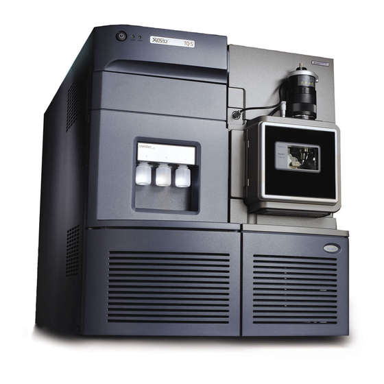
Page 26: Waters Xevo Tq-S
Optional atmospheric pressure gas chromatography (APGC) ® • Optional TRIZAIC UPLC • Optional ionKey source You can also use the Xevo TQ-S with the following optional third-party sources: ® • Direct analysis in real time (DART • Desorption electrospary ionization (DESI) •... - Page 27 Waters Xevo TQ-S Waters Xevo TQ-S: Source enclosure February 28, 2014, 715002212 Rev. C...
-
Page 28: Acquity Uplc/Ms Xevo Tq-S Systems
ACQUITY UPLC column, and software to control the system. 1. In Waters documents, the term “fluidics” refers to the IntelliStart Fluidics system, which is the instrument’s onboard system that delivers sample and solvent to the probe of the mass spectrometer. - Page 29 Waters Xevo TQ-S For further information, see the ACQUITY UPLC System Operator’s Guide or Controlling Contamination in LC/MS Systems (part number 715001307). You can find these documents on www.waters.com; click Services & Support > Support. Waters ACQUITY Xevo TQ-S UPLC/MS system:...
-
Page 30: Non-Acquity Devices For Use With The Xevo Tq-S
For further information, see the nanoACQUITY UPLC System Operator’s Guide or Controlling Contamination in LC/MS Systems (part number 715001307). You can find these documents on www.waters.com; click Services & Support > Support. ACQUITY UPLC M-Class system The ACQUITY UPLC M-Class system is designed for nano-scale and micro-scale separations. -
Page 31: Software And Data System
Waters Xevo TQ-S Software and data system You can use MassLynx software v4.1 or UNIFI software to control the mass spectrometer. Both MassLynx software and UNIFI software enable these major operations: • Configuring the system • Creating LC and MS/MS methods that define operating parameters for a •... -
Page 32: Ionization Techniques And Source Probes
Available source options can vary depending on the software used to Note: operate the Xevo TQ-S. Refer to the MassLynx or UNIFI online Help for more information about supported sources. In ESI, a strong electrical charge is applied to the eluent as it emerges from a nebulizer. -
Page 33: Dual-Mode Appi/Apci Source
Ionization techniques and source probes Dual-mode APPI/APCI source The optional, combined APPI/APCI source comprises an IonSABRE II probe and the APPI lamp drive assembly. The APPI lamp drive assembly comprises a UV lamp and a repeller electrode. In addition, a specially shaped, dual, APPI/APCI corona pin can be used. -
Page 34: Atmospheric Solids Analysis Probe
See the Atmospheric Solids Analysis Probe Operator’s Guide Supplement for further details. APGC The Waters APGC couples an Agilent GC with the Xevo TQ-S. Doing so enables you to perform LC and GC analyses in the same system, without compromising performance. The APGC provides complementary information to the LC/MS instrument, enabling analysis of compounds of low molecular weight and low-to-intermediate polarity. -
Page 35: Intellistart Fluidics System
IntelliStart fluidics system See the ACQUITY UPLC M-Class System Guide and the ionKey/MS System Guide for further details. “ionKey source” on page See also: IntelliStart fluidics system Overview The IntelliStart fluidics system is a solvent delivery system built into the mass spectrometer. -
Page 36: System Components
1 Waters Xevo TQ-S Overview System components The onboard system incorporates a 6-port selector valve, a multi-position diverter valve, a pump, and three sample reservoirs. The sample reservoirs are mounted on the instrument’s front panel. When you select a solvent from the Instrument Console, an LED illuminates the appropriate reservoir. -
Page 37: Ms Operating Modes
MS operating modes The ions then pass to the first quadrupole, where they can be filtered according to their mass-to-charge ratio (m/z). The mass-separated ions pass into the T-Wave/ScanWave™ collision cell, where they undergo collision-induced dissociation (CID) or pass to the second quadrupole. -
Page 38: Ms/Ms Operating Modes
1 Waters Xevo TQ-S Overview MS/MS analysis. See the mass spectrometer’s online Help for further information. Use the selected ion recording (SIR) mode for quantitation when you cannot find a suitable fragment ion to perform a more specific multiple reaction... -
Page 39: Product (Daughter) Ion Mode
MS/MS operating modes Product (daughter) ion mode Product ion mode is the most commonly used MS/MS operating mode. You can specify an ion of interest for fragmentation in the collision cell, thus yielding structural information. Product ion mode: Collision cell Static (at precursor mass) Pass all masses Scanning... -
Page 40: Precursor (Parent) Ion Mode
1 Waters Xevo TQ-S Overview Precursor (parent) ion mode Precursor ion mode: Collision cell Scanning Pass all masses Static (at product mass) Typical application You typically use the precursor ion mode for structural elucidation—that is, to complement or confirm product scan data—by scanning for all the precursors of a common product ion. -
Page 41: Constant Neutral Loss Mode
MS/MS operating modes • Drug metabolite and pharmacokinetic studies • Environmental studies; for example, pesticide and herbicide analysis • Forensic or toxicology studies; for example, screening for target drugs in sports testing MRM mode does not produce a spectrum, because only one transition is monitored at a time. -
Page 42: Scanwave Daughter Scan Mode
“Product (daughter) ion mode” on page Leak sensors Leak sensors in the drip trays of the Xevo TQ-S continuously monitor the instrument for leaks. A leak sensor stops system flow when its optical sensor detects approximately 1.5 mL of accumulated, leaked liquid in its surrounding reservoir. -
Page 43: Vacuum System
Vacuum system Vacuum system Two external roughing (rotary vane) pumps (a dry-pump option is available) and three internal turbomolecular pumps create the source vacuum. The turbomolecular pumps evacuate the analyzer and ion transfer region. Vacuum leaks and electrical or vacuum pump failures cause vacuum loss, which protective interlocks guard against. - Page 44 1 Waters Xevo TQ-S Overview February 28, 2014, 715002212 Rev. C...
-
Page 45: Preparing The Mass Spectrometer For Operation
Preparing the Mass Spectrometer for Operation This chapter describes how to start and shut down the mass spectrometer. Contents: Topic Page Starting the mass spectrometer ............46 Preparing the IntelliStart Fluidics system........51 Rebooting the mass spectrometer ........... 55 Leaving the mass spectrometer ready for operation...... 56 Emergency shutdown of the mass spectrometer ...... -
Page 46: Starting The Mass Spectrometer
2 Preparing the Mass Spectrometer for Operation Starting the mass spectrometer This instrument is compatible with the ACQUITY UPLC system; if you are not using an ACQUITY UPLC system, refer to the documentation relevant to the system you are using (see “Non-ACQUITY devices for use with the Xevo TQ-S”... - Page 47 Starting the mass spectrometer Press the power switch on the top, left-hand side of the mass spectrometer and ACQUITY instruments. Each system instrument runs a series of startup tests. Result: Wait 3 minutes for the embedded PC to initialize, as indicated by an audible alert.
-
Page 48: Verifying The Instrument's State Of Readiness
Tip: IntelliStart software displays corrective actions in the Instrument Console. UNIFI software: From the Xevo TQ-S console, in the Maintain pane, click Vacuum. On the Status page, click Pump. The Operate LED remains off. Tip: Wait a minimum of 2 hours for the instrument to be fully pumped down (evacuated). -
Page 49: Tuning And Calibration Information
Starting the mass spectrometer Operate LED The Operate LED, located on the right-hand side of the power LED, indicates the operating condition. See the mass spectrometer’s online Help topic “Monitoring the mass spectrometer LEDs” for details on the Operate LED indications. Tuning and calibration information You must tune and, if necessary, calibrate the instrument prior to use. -
Page 50: Running The Mass Spectrometer At High Flow Rates
Running the mass spectrometer at high flow rates The ACQUITY UPLC system runs at high flow rates. To optimize desolvation, and thus sensitivity, run the ACQUITY Xevo TQ-S system at appropriate gas flows and desolvation temperatures. When you specify a flow rate, IntelliStart software automatically specifies the settings shown in the following table. -
Page 51: Preparing The Intellistart Fluidics System
Preparing the IntelliStart Fluidics system Preparing the IntelliStart Fluidics system For additional information, see Appendix D “Connecting the liquid waste line” on page 260. To avoid accidental spillage damaging the instrument, do not Caution: store large-volume solvent reservoirs on top of the instrument. Installing the reservoir bottles Use standard reservoir bottles (30-mL) for instrument setup and calibration. - Page 52 2 Preparing the Mass Spectrometer for Operation For each reservoir bottle, ensure that the end of the solvent delivery tube is positioned so that it is close to, but does not touch, the bottom of the bottle (see page 53). To avoid becoming contaminated with biohazards or Warning: toxic compounds, always wear chemical-resistant, powder-free...
-
Page 53: Adjusting The Solvent Delivery Tube Positions
Preparing the IntelliStart Fluidics system Adjusting the solvent delivery tube positions For correct operation of the IntelliStart Fluidics system, you must adjust each solvent delivery tube so that its end is close to, but does not touch, the bottom of the reservoir bottle or low volume vial. To adjust the position of a solvent delivery tube: Open the access door to the fluidics pump (see the figure on page... -
Page 54: Purging The Infusion Pump
2 Preparing the Mass Spectrometer for Operation Purging the infusion pump Whenever you replace a solution bottle, purge the infusion pump with the solution that you are going to use next (see the mass spectrometer’s online Help for details). Depending on the solutions used, the instrument’s solvent delivery system can require more than one purge cycle to minimize carryover. -
Page 55: Rebooting The Mass Spectrometer
Rebooting the mass spectrometer Rebooting the mass spectrometer The reset button shuts down the electronics momentarily and causes the mass spectrometer to reboot. Reboot the mass spectrometer when either of these conditions applies: • The mass spectrometer software fails to initialize. •... -
Page 56: Leaving The Mass Spectrometer Ready For Operation
2 Preparing the Mass Spectrometer for Operation Leaving the mass spectrometer ready for operation Leave the mass spectrometer in Operate mode, except in the following cases: • When performing routine maintenance. • When changing the source. • When leaving the mass spectrometer unused for a long period. In these instances, put the mass spectrometer in Standby mode (see the online Help for details). -
Page 57: Changing The Mode Of Operation
For details about other Waters and third-party source options, refer to the documentation supplied with the source. Available source options can vary depending on the software used Note: to operate the Xevo TQ-S. Refer to the MassLynx or UNIFI online Help for more information about supported sources. Contents: Topic Page ESI mode .................. -
Page 58: Installing The Esi Probe
3 Changing the Mode of Operation For further details, see “ESI” on page The following sections explain how to install and remove an ESI probe. Installing the ESI probe Required materials • Chemical-resistant, powder-free gloves • Sharp knife or PEEK tubing cutter To avoid personal contamination with biohazards or Warning: toxic materials, and to avoid spreading contamination to... - Page 59 ESI mode With the probe label facing you, carefully slide the ESI probe into the hole in the probe adjuster assembly. The probe location dowel must align with the location Requirement: hole of the probe adjuster assembly. Probe label Probe location dowel Location hole of the probe adjuster assembly TP03129...
- Page 60 3 Changing the Mode of Operation ESI probe, mounted on the source enclosure: Vernier probe adjuster ESI probe Probe locking ring ESI probe cable Vertical probe High voltage adjuster connector Source window Source enclosure release TP03128 To avoid nitrogen leakage, fully tighten the probe locking Caution: ring.
- Page 61 ESI mode Using PEEK tubing greater than or equal to 0.004-inch ID, connect port 2 (the top port) of the diverter valve to the ESI probe. To reduce peak broadening, use 0.004-inch ID tubing Recommendation: for sample flow rates ≤1.2 mL/min; use 0.005-inch ID tubing for sample flow rates >1.2 mL/min.
-
Page 62: Removing The Esi Probe
3 Changing the Mode of Operation Removing the ESI probe Required materials Chemical-resistant, powder-free gloves To avoid personal contamination with biohazards or Warning: toxic materials, and to avoid spreading contamination to uncontaminated surfaces, wear clean, chemical-resistant, powder-free gloves while performing this procedure. The LC system connections, ESI probe, and source can be contaminated. -
Page 63: Optimizing The Esi Probe For Esci Operation
APCI mode Optimizing the ESI probe for ESCi operation See the mass spectrometer’s online Help for details on how to optimize the ESI probe for ESCi operation. APCI mode APCI mode, an option for the mass spectrometer, produces singly charged protonated or deprotonated molecules for a broad range of nonvolatile analytes. -
Page 64: Installing The Ionsabre Ii Probe
3 Changing the Mode of Operation Installing the IonSABRE II probe Required materials • Chemical-resistant, powder-free gloves • Sharp knife or PEEK tubing cutter To avoid personal contamination with biohazards or Warning: toxic materials, and to avoid spreading contamination to uncontaminated surfaces, wear clean, chemical-resistant, powder-free gloves while performing this procedure. - Page 65 APCI mode With the probe label facing you, carefully slide the IonSABRE II probe into the hole in the probe adjuster assembly, ensuring that the probe location dowel aligns with the probe adjuster assembly location hole. Probe label Probe location dowel Probe adjuster assembly location hole TP03129...
- Page 66 3 Changing the Mode of Operation IonSABRE II probe mounted on the source enclosure: IonSABRE II probe Probe locking ring Vernier probe adjuster Vertical probe adjuster Source window Source enclosure release TP03128 Open the access door to the fluidics valve (see the figure on page 29).
-
Page 67: Removing The Ionsabre Ii Probe
Combined APPI/APCI source Removing the IonSABRE II probe Required materials Chemical-resistant, powder-free gloves To avoid personal contamination with biohazards or Warning: toxic materials, and to avoid spreading contamination to uncontaminated surfaces, wear clean, chemical-resistant, powder-free gloves while performing this procedure. The LC system connections, IonSABRE II probe, and source can be contaminated. -
Page 68: Apci Operation
3 Changing the Mode of Operation APPI mode: IonSABRE II probe Sample ions Sample molecules APPI lamp drive assembly Sample cone Photons from UV lamp Repeller electrode the UV lamp The IonSABRE II probe introduces vaporized sample into the source where photons generated by an ultra-violet (UV) lamp (mounted in the APPI lamp drive assembly) produce sample ions. -
Page 69: Dual-Mode Operation
Combined APPI/APCI source The IonSABRE II probe introduces vaporized sample into the source. The sample passes between the sample cone and the corona pin, which typically operates with a discharge current of 5 µA. The corona discharge generates ions that react with the mobile phase molecules to produce stable reagent ions. -
Page 70: The Combined Appi/Apci Source Components
3 Changing the Mode of Operation Dual operation in APPI mode: Repeller electrode with IonSABRE II probe voltage applied Sample cone Corona pin inactive Photons from the UV lamp The combined APPI/APCI source components The combined APPI/APCI source comprises the standard IonSABRE II probe and a source enclosure with an APPI lamp drive incorporated. - Page 71 Combined APPI/APCI source The combined APPI/APCI source enclosure: APPI lamp drive assembly To prevent damage to the corona pin and lamp assembly, Caution: ensure that the lamp assembly does not touch the corona pin when the source enclosure door is closed. The UV lamp, which you ignite via a control in the MassLynx software Tune window, provides a constant photon output.
-
Page 72: Installing The Combined Appi/Apci Source
3 Changing the Mode of Operation APPI lamp drive assembly inside the source enclosure: APPI lamp drive assembly Source enclosure IonSABRE II probe UV lamp and repeller electrode TP03201 Installing the combined APPI/APCI source Required materials Chemical-resistant, powder-free gloves To avoid personal contamination with biohazards or Warning: toxic materials, and to avoid spreading contamination to uncontaminated surfaces, wear clean, chemical-resistant,... - Page 73 Combined APPI/APCI source Remove the probe from the currently installed source: • If you are removing an ESI probe, see page • If you are removing an IonSABRE II probe, see page Remove the existing source enclosure (see page 100). Install the combined APPI/APCI source enclosure (see page 102).
-
Page 74: Nanoflow Esi Source
3 Changing the Mode of Operation To remove the combined APPI/APCI source Prepare the instrument for working on the source (see page 98). To avoid burn injuries, take great care while working Warning: with the probe and source; these components can be hot. Remove the IonSABRE II probe (see page 67). - Page 75 NanoFlow ESI source NanoFlow source, stage and microscope camera: Microscope camera Sprayer enclosure X, Y, Z stage TP03199 A sprayer is mounted on an X, Y, Z stage (three-axis manipulator), which slides on a pair of guide rails that allow its withdrawal from the source enclosure for maintenance and changes.
-
Page 76: Installing The Nanoflow Source
3 Changing the Mode of Operation Installing the NanoFlow source Required materials Chemical-resistant, powder-free gloves To avoid personal contamination with biohazards or Warning: toxic materials, and to avoid spreading contamination to uncontaminated surfaces, wear clean, chemical-resistant, powder-free gloves while performing this procedure. The source components can be contaminated. - Page 77 For details regarding how to fit each sprayer, see the corresponding Tip: reference: • Waters Universal NanoFlow Sprayer Installation and Maintenance Guide (part number 71500110107) • “Fitting a borosilicate glass capillary (nanovial)” on page 78 • Capillary Electrophoresis/Capillary Electrochromatography Sprayer User's Guide (part number 6666522) Open the instrument’s source interface door (see the figure on...
-
Page 78: Fitting A Borosilicate Glass Capillary (Nanovial)
3 Changing the Mode of Operation voltage (the voltage applied to the sprayer assembly) and the sampling cone voltage are disabled. High voltage cable 11. Close the instrument’s source interface door. Fitting a borosilicate glass capillary (nanovial) Required materials • Chemical-resistant, powder-free gloves •... - Page 79 NanoFlow ESI source To fit a borosilicate glass capillary (nanovial): To avoid lacerations, puncture injuries, and possible Warning: contamination with biohazardous and toxic samples, do not touch the sharp end of the capillary. To avoid damaging capillaries, take great care when handling Caution: them;...
- Page 80 3 Changing the Mode of Operation Carefully remove the new borosilicate glass capillary from its case by lifting vertically while pressing on the foam with two fingers. Foam Capillary Load sample into the capillary using a fused silica syringe needle or a GELoader tip, minimizing any bubbles between the capillary tip and the sample.
-
Page 81: Positioning The Borosilicate Glass Capillary Tip
NanoFlow ESI source Sprayer Assembly: PTFE tubing Ferrule Union Knurled nut Blue conductive elastomer Glass capillary 5 mm 12. Screw the sprayer back into the assembly. 13. Replace the sprayer cover. 14. On the MassLynx MS Tune window, ensure that the Capillary parameter on the ES+/- Source tab is set to 0 kV. -
Page 82: Restarting A Stalled Borosilicate Glass Capillary Electrospray
2 mm. Capillary tip position: Cone aperture diameter For tuning instructions, see the MassLynx, Xevo TQ-S online help, “Tuning manually for NanoFlow operation”. Restarting a stalled borosilicate glass capillary electrospray Should the spray stop, you can restart it. To do so, in the Tune window, set Capillary to 0 kV. -
Page 83: Installing The Ionkey Source
ionKey source Installing the ionKey source The ionKey source enclosure comprises the iKey docking port, the iKey locking handle, the sprayer-enclosure, and a microscope camera. ionKey source: Microscope camera iKey docking port iKey locking/unlocking handle Front cover Required materials • Chemical-resistant, powder-free gloves •... - Page 84 3 Changing the Mode of Operation Using two hands, fit the ionKey source enclosure to the two supporting studs on the source adaptor housing. Swing the source enclosure to the closed position, ensuring it locks into place. To avoid damaging the µSample manager or mass Caution: spectrometer, •...
- Page 85 ionKey source ionKey source connections: Options cable High voltage cable Data/power cable to PSPI connector on Fluid inlet line TP03574 Fluid infusion line Fluid waste line Connect the data/power cable to the PSPI connector on the rear of the µSample manager, and use a screwdriver to firmly tighten the connector screws.
- Page 86 3 Changing the Mode of Operation Source connections to mass spectrometer: Options cable High voltage cable Data/power cable to QSPI connector on µSample manager Connect the high voltage cable (white) to the high voltage supply outlet on the mass spectrometer. Connect the options cable (blue) to the options port on the mass spectrometer.
- Page 87 ionKey source Identify the three fluid lines by the part numbers printed on their shrink-wrap tubing. ionKey tubing assemblies: Part Number Description 430003899 Infusion line 430003901 Inlet line 430003903 Waste line Fluid line aperture: Aperture closed Fluid line aperture Aperture open (spring-loaded) February 28, 2014, 715002212 Rev.
-
Page 88: Installing Ionkey Source Software
Installing ionKey source software If you are installing an ionKey source on your Xevo TQ-S for the first time, you must install the appropriate MassLynx software SCN and the ACQUITY M-Class driver pack. For further details, see the following documents: •... -
Page 89: Installing The Camera In The Ionkey Source
ionKey source Installing the camera in the ionKey source To install the camera in the ionKey source: Connect the camera cable from the video output connector on the mass spectrometer’s rear panel to the video-to-USB converter box. Connect the video-to-USB converter box to a USB port on the mass spectrometer’s workstation. - Page 90 3 Changing the Mode of Operation • ¼-inch wrench To avoid personal contamination with biohazards or Warning: toxic materials, and to avoid spreading contamination to uncontaminated surfaces, wear clean, chemical-resistant, powder-free gloves while performing this procedure. The source components can be contaminated. To avoid electric shock, prepare the instrument for work Warning: performed on its source before beginning this procedure.
-
Page 91: Maintenance Procedures
Maintenance Procedures This chapter provides the maintenance guidelines and procedures necessary to maintain the mass spectrometer’s performance. Keep to a maintenance schedule, and perform maintenance as required and described in this chapter. Contents: Topic Page Maintenance schedule ..............92 Spare parts ..................95 Troubleshooting with Connections INSIGHT ........ -
Page 92: Maintenance Schedule
4 Maintenance Procedures Contents: Topic Page Cleaning or replacing the corona pin ..........190 Replacing the IonSABRE II probe heater........191 Replacing the ion block source heater..........195 Replacing the source assembly seals ..........199 Replacing the air filter..............203 APPI/APCI source—changing the UV lamp bulb...... - Page 93 Maintenance schedule Maintenance schedule: Procedure Frequency For information... Gas ballast the Edwards™ page 127. page 127. XDS46i oil-free roughing pump. Clean the source components. When source page 128. components are visibly fouled, the background or high-peak contaminants are unacceptably high, or sensitivity decreases to unacceptable levels.
- Page 94 4 Maintenance Procedures Maintenance schedule: Procedure Frequency For information... Replace the IonSABRE II If the heater fails to page 191. probe heater. (Options using heat when the the IonSABRE II probe only.) instrument is pumped down (evacuated). Replace the ion block heater If the heater fails to page 195.
-
Page 95: Spare Parts
Spare parts Spare parts Waters recommends that you replace only the parts mentioned in this ® document. For information about spare parts, see the Waters Quality Parts Locator on the Waters Web site’s Services/Support page. February 28, 2014, 715002212 Rev. C... -
Page 96: Troubleshooting With Connections Insight
Connections INSIGHT is an “intelligent” device management (IDM) Web service that enables Waters to provide proactive service and support for the ACQUITY UPLC system. To use Connections INSIGHT, you must install its service agent software on your workstation. In a client/server system, the service agent must also be installed on the computer from which you control the system. -
Page 97: Safety And Handling
Safety and handling Safety and handling Bear in mind the following safety considerations when performing maintenance procedures: To avoid personal contamination with biohazards or Warning: toxic materials, and to avoid spreading contamination to uncontaminated surfaces, wear clean, chemical-resistant, powder-free gloves while handling instrument components. To prevent injury, always observe Good Laboratory Practices Warning: when handling solvents, changing tubing, or operating the instrument. -
Page 98: Preparing The Instrument For Working On The Source
In the Instrument Console, click Stop Flow , to stop the LC flow. If column flow is required, divert the LC flow to waste: Note: In the Instrument Console system tree, expand Xevo TQ-S Detector, Interactive Fluidics. February 28, 2014, 715002212 Rev. C... - Page 99 Preparing the instrument for working on the source Click Control Select Waste as the flow state. In the Instrument Console, click Standby , and confirm that the Operate indicator is not illuminated. Wait 3 minutes, to allow the desolvation gas flow to cool the probe and source.
-
Page 100: Removing And Refitting The Source Enclosure
4 Maintenance Procedures Removing and refitting the source enclosure The optional combined APPI/APCI, NanoFlow, TRIZAIC and ionKey sources are supplied as a complete source enclosure. To fit them, you must first remove the standard source enclosure. Removing the source enclosure from the instrument Required materials Chemical-resistant, powder-free gloves To avoid personal contamination with biohazards or... - Page 101 Removing and refitting the source enclosure Using both hands, grasp the source enclosure, and lift it vertically off the two supporting studs on the source adaptor housing. Cable storage positions Supporting stud TP03164 Source enclosure Store the cables neatly by plugging them into the cable-storage positions on the rear of the source enclosure.
-
Page 102: Fitting The Source Enclosure To The Instrument
4 Maintenance Procedures Fitting the source enclosure to the instrument Required materials Chemical-resistant, powder-free gloves To avoid personal contamination with biohazards or Warning: toxic materials, and to avoid spreading contamination to uncontaminated surfaces, wear clean, chemical-resistant, powder-free gloves while performing this procedure. The source components can be contaminated. -
Page 103: Installing The Corona Pin In The Source
Installing and removing the corona pin Installing the corona pin in the source Required materials Chemical-resistant, powder-free gloves To avoid personal contamination with biohazards or Warning: toxic materials, and to avoid spreading contamination to uncontaminated surfaces, wear clean, chemical-resistant, powder-free gloves while performing this procedure. The LC system connections, ESI probe, and source can be contaminated. - Page 104 4 Maintenance Procedures Corona pin mounting contact: Corona pin mounting contact blanking plug TP03130 To avoid puncture wounds, handle the corona pin with Warning: care; the pin tip is sharp. Fit the corona pin to the mounting contact, ensuring that the corona pin is securely mounted.
-
Page 105: Removing The Corona Pin From The Source
Installing and removing the corona pin Close the source enclosure. Look through the source window, and use the vernier probe adjuster to position the probe tip so that it is pointing approximately midway between the tips of the sample cone and corona pin. Vernier probe adjuster Source window TP03128... - Page 106 4 Maintenance Procedures To remove the corona pin from the source: Prepare the instrument for working on the source (see page 98). To avoid burn injuries, take great care while working Warning: with the instrument’s source enclosure open; the source can be hot. To avoid puncture wounds, take great care while Warning: working with the source enclosure open if an ESI probe is fitted;...
-
Page 107: Operating The Source Isolation Valve
Operating the source isolation valve Operating the source isolation valve You must close the source isolation valve to isolate the source from the instrument vacuum system for certain maintenance procedures. Required materials Chemical-resistant, powder-free gloves To avoid personal contamination with biohazards or Warning: toxic materials, and to avoid spreading contamination to uncontaminated surfaces, wear clean, chemical-resistant,... - Page 108 4 Maintenance Procedures Close the source isolation valve by turning its handle counterclockwise, to the vertical position. Isolation valve handle in closed position February 28, 2014, 715002212 Rev. C...
- Page 109 Operating the source isolation valve To avoid personal contamination with biohazards or Warning: toxic materials, and to avoid spreading contamination to uncontaminated surfaces, wear clean, chemical-resistant, powder-free gloves while performing this procedure. The source components can be contaminated. To avoid puncture wounds, take great care while working with Warning: the source enclosure open if one or both of these conditions apply: •...
-
Page 110: Removing O-Rings And Seals
4 Maintenance Procedures Removing O-rings and seals When performing certain maintenance procedures, you must remove O-rings or seals from instrument components. An O-ring removal kit is provided with the instrument. O-ring removal kit: Tool 1 Tool 2 To remove an O-ring: To avoid damage, be careful not to scratch components with Caution: the removal tool when removing an O-ring or seal. -
Page 111: Cleaning The Instrument Case
Cleaning the instrument case Cleaning the instrument case To avoid damage, do not use abrasives or solvents to clean the Caution: instrument’s case. Use a soft cloth, dampened with water, to clean the outside surfaces of the mass spectrometer. Emptying the nitrogen exhaust trap bottle Inspect the nitrogen exhaust trap bottle in the instrument’s exhaust line daily, and empty it before it is more than 10% full. - Page 112 4 Maintenance Procedures Required materials Chemical-resistant, powder-free gloves To empty the nitrogen exhaust trap bottle: To stop the LC flow, follow the action below for your software: Software Action MassLynx In the Instrument Console, click Stop Flow UNIFI On the System Console tool bar, click Stop Flow Pull the source enclosure release (located at the bottom, right-hand side) outward, and swing open the enclosure.
-
Page 113: Maintaining The Oerlikon Leybold Oil-Filled Roughing Pumps
Maintaining the Oerlikon Leybold oil-filled roughing pumps To start the LC flow, follow the action below for your software: Software Action MassLynx In the Instrument Console, click Start Flow UNIFI On the System Console tool bar, click Start Flow Maintaining the Oerlikon Leybold oil-filled roughing pumps In addition to the roughing pump maintenance requirements Requirement:... - Page 114 4 Maintenance Procedures Oerlikon Leybold roughing pump: Gas ballast valve Oil filler plug Oil level sight glass Oil drain plug February 28, 2014, 715002212 Rev. C...
-
Page 115: Gas Ballasting The Oerlikon Leybold Roughing Pumps
Maintaining the Oerlikon Leybold oil-filled roughing pumps Gas ballasting the Oerlikon Leybold roughing pumps Failure to routinely gas ballast the roughing pumps shortens oil Important: life and, consequently, pump life. The roughing pumps draw large quantities of solvent vapors that condense in the pump oil, diminishing pumping efficiency. -
Page 116: Inspecting The Roughing Pump Oil Levels
4 Maintenance Procedures Inspecting the roughing pump oil levels To ensure correct operation of the roughing pumps, do not Caution: operate them with the oil level at less the minimum level, as indicated in the pumps’ sight glasses. This procedure does not apply to an Edwards oil-free roughing pump. Note: You must determine the oil levels while the roughing pumps Requirement:... - Page 117 Maintaining the Oerlikon Leybold oil-filled roughing pumps Disconnect the power cords for the mass spectrometer and both roughing pumps from the main power source. Allow the oil to settle in the pump. To avoid personal contamination with biohazards Warning: or toxic materials, always wear chemical-resistant, powder-free gloves when adding or replacing pump oil.
- Page 118 4 Maintenance Procedures Start the mass spectrometer (see page 46). After you add oil to the pump, the following situations can occur: Tips: • The oil level drops slightly during the first month of operation. • The oil changes color (darkens) over time. •...
-
Page 119: Replacing The Roughing Pumps' Oil And Oil Demister Elements
Maintaining the Oerlikon Leybold oil-filled roughing pumps Replacing the roughing pumps’ oil and oil demister elements Replace the roughing pumps’ oil and oil demister elements annually. This procedure is not required for an Edwards oil-free roughing pump. Note: Required materials •... - Page 120 4 Maintenance Procedures To avoid personal contamination with biohazards or Warning: toxic materials, always wear chemical-resistant, powder-free gloves when adding or replacing oil. The roughing pump oil can be contaminated with analyte accumulated during normal operation. To avoid burn injuries, take great care while working Warning: with the roughing pumps: they can be hot.
- Page 121 Maintaining the Oerlikon Leybold oil-filled roughing pumps To fill the roughing pumps with oil: Using the funnel, pour 1 L of vacuum oil, Leybonol LVO 110 or Anderol GD32, into the oil filler aperture. Use only the specified vacuum oils: Leybonol LVO 110 or Important: Anderol GD32.
- Page 122 4 Maintenance Procedures To remove the roughing pumps’ oil demister elements: Use the 6-mm Allen wrench to remove the 4 bolts securing the exhaust flange to the roughing pump. Securing bolt Exhaust flange TP02694 Using both hands, carefully remove the exhaust flange and oil demister element from the roughing pump.
- Page 123 Maintaining the Oerlikon Leybold oil-filled roughing pumps Use the 10-mm wrench to remove the nut that secures the oil demister element to the exhaust flange. Spring Securing nut TP02686 Holding the oil demister element slightly elevated, to prevent the loss of the spring, remove its flange.
- Page 124 4 Maintenance Procedures Remove the spring from the oil demister element. To avoid spreading contamination, ensure that the Warning: oil demister element is correctly disposed of according to local environmental regulations.The oil demister element can be contaminated with biohazards or toxic materials. Dispose of the oil demister element in accordance with local environmental regulations.
- Page 125 Maintaining the Oerlikon Leybold oil-filled roughing pumps Use the 10-mm wrench to fit and tighten the nut that secures the oil demister element to the exhaust flange. TP02686 1 mm exposed thread after tightening Ensure that the inscription “TOP” is at the top of the oil demister element, and, using both hands, carefully fit the oil demister element and exhaust flange to the roughing pump.
- Page 126 4 Maintenance Procedures To prepare for operation after changing the roughing pumps’ oil and oil demister elements: Connect the power cords for the mass spectrometer and both roughing pumps to the main power source. Start the mass spectrometer (see page 46).
-
Page 127: Gas Ballasting The Edwards Xds35I Oil-Free Roughing Pump
Gas ballasting the Edwards XDS35i oil-free roughing pump Gas ballasting the Edwards XDS35i oil-free roughing pump In addition to the roughing pump gas ballasting procedure Requirement: detailed here, please refer to the manufacturer’s documentation provided with the instrument. Failure to routinely gas ballast the roughing pump shortens pump Important: life. -
Page 128: Cleaning The Source Components
4 Maintenance Procedures Use of the gas ballast control In normal use, the gas ballast control should be off (no-gas ballast). To select no-gas ballast, turn the control position to 0. Doing so pumps gases fully, achieving ultimate vacuum. To select low-flow gas ballast, turn the control to position I for approxiamtely one hour. -
Page 129: Cleaning The Sampling Cone Assembly
Cleaning the sampling cone assembly Cleaning the sampling cone assembly You can remove the sampling cone assembly (comprising the sample cone, O-ring, and cone gas nozzle) for cleaning without venting the instrument. Removing the sampling cone assembly from the source Required materials Chemical-resistant, powder-free gloves To avoid personal contamination with biohazards or... - Page 130 4 Maintenance Procedures Grasp the cone gas nozzle handle, and use it to rotate the sampling cone assembly 90 degrees, moving the handle from the vertical to the horizontal position. Sampling cone assembly Cone gas nozzle handle TP03131 To avoid damaging the instrument by sudden venting, do Caution: not open the isolation valve at any time while the sampling cone assembly is removed from the ion block assembly.
-
Page 131: Disassembling The Sampling Cone Assembly
Cleaning the sampling cone assembly Disassembling the sampling cone assembly Required materials • Chemical-resistant, powder-free gloves • Combined 2.5-mm Allen wrench and cone extraction tool To avoid personal contamination with biohazards or Warning: toxic materials, and to avoid spreading contamination to uncontaminated surfaces, wear clean, chemical-resistant, powder-free gloves when working with the sampling cone assembly. - Page 132 4 Maintenance Procedures Insert the collar in the sample cone. To avoid damaging the fragile sample cone, do not place Caution: it on its tip; instead, place it on its flanged base. Rotate and lift the tool and collar to remove the sample cone from the cone gas nozzle.
- Page 133 Cleaning the sampling cone assembly Remove the O-ring from the sample cone. Cone gas nozzle Cone gas nozzle handle O-ring To avoid spreading contamination, dispose of the Warning: O-ring or seal in accordance with local environmental regulations. If the O-ring shows signs of deterioration or damage, dispose of it in accordance with local environmental regulations.
-
Page 134: Cleaning The Sample Cone And Cone Gas Nozzle
4 Maintenance Procedures Cleaning the sample cone and cone gas nozzle Required materials • Chemical-resistant, powder-free gloves. • Appropriately sized glass vessels in which to completely immerse components when cleaning. Use only glassware not previously cleaned with surfactants. • HPLC-grade (or better) methanol. •... - Page 135 Cleaning the sampling cone assembly Place the vessels in the ultrasonic bath for 30 minutes. If you used formic acid in the cleaning solution, rinse the components by immersing them in separate glass vessels containing water and then placing the vessels in the ultrasonic bath for 20 minutes. To avoid recontaminating the components, wear clean, Caution: chemical-resistant, powder-free gloves for the rest of this...
-
Page 136: Assembling The Sampling Cone Assembly
4 Maintenance Procedures Assembling the sampling cone assembly Required materials Chemical-resistant, powder-free gloves Caution: • To avoid recontaminating the sampling cone assembly, wear clean chemical-resistant, powder-free gloves during this procedure. • To avoid damaging the fragile sample cone, do not place it on its tip; instead, place it on its flanged base. -
Page 137: Fitting The Sampling Cone Assembly To The Source
Cleaning the sampling cone assembly Fitting the sampling cone assembly to the source Required materials Chemical-resistant, powder-free gloves To avoid personal contamination with biohazards or Warning: toxic materials, and to avoid spreading contamination to uncontaminated surfaces, wear clean, chemical-resistant, powder-free gloves when working with the source components. To avoid puncture wounds, take great care while working with Warning: the source enclosure open if one or both of these conditions apply:... - Page 138 4 Maintenance Procedures Hold the sampling cone assembly so that the cone gas nozzle handle is oriented horizontally and at the top, and then slide the sampling cone assembly into the ion block assembly. Ion block assembly TP03132 Sampling cone assembly Grasp the handle of the cone gas nozzle, and use the handle to rotate the sampling cone assembly 90 degrees, moving the handle downward, from the horizontal to the vertical position.
-
Page 139: Cleaning The Ion Block Assembly
Cleaning the ion block assembly Cleaning the ion block assembly Clean the ion block assembly if cleaning the sample cone and cone gas nozzle fails to increase signal sensitivity. Removing the ion block assembly from the source assembly Required materials •... - Page 140 4 Maintenance Procedures Removing the source enclosure aids access to the ion block Rationale: assembly. Close the source isolation valve (see page 107). Use the combined 2.5-mm Allen wrench and cone extraction tool to unscrew the 4, captive, ion block assembly securing screws. Ion block assembly securing screws TP03130...
-
Page 141: Disassembling The Source Ion Block Assembly
Cleaning the ion block assembly Disassembling the source ion block assembly Required materials • Chemical-resistant, powder-free gloves • Combined 2.5-mm Allen wrench and cone extraction tool • O-ring removal kit To avoid personal contamination with biohazards or Warning: toxic materials, and to avoid spreading contamination to uncontaminated surfaces, wear clean, chemical-resistant, powder-free gloves when working with the ion block assembly. - Page 142 4 Maintenance Procedures To ensure correct operation of the ion block assembly Caution: after reassembly: • do not remove the sampling cone assembly retaining blocks; • do not adjust the screws securing the sampling cone assembly retaining blocks. Slide the sampling cone assembly out of the ion block assembly. Use the combined 2.5-mm Allen wrench and cone extraction tool to loosen the 2 captive screws securing the ion block cover plate.
- Page 143 Cleaning the ion block assembly Grasp the isolation valve, and pull it out of the ion block. Isolation valve O-ring Use the O-ring removal kit to carefully remove the isolation valve O-ring (see page 110). To prevent spreading contamination, dispose of the Warning: isolation valve O-ring according to local environmental regulations.
- Page 144 4 Maintenance Procedures Use the combined 2.5-mm Allen wrench and cone extraction tool to loosen the captive PEEK terminal block securing screw. Heater cartridge assembly wires PEEK terminal block securing screw February 28, 2014, 715002212 Rev. C...
- Page 145 Cleaning the ion block assembly To avoid damaging the heater cartridge assembly wires, Caution: do not bend or twist them when removing the assembly and ceramic heater mounting block from the ion block. 10. Carefully remove the PEEK terminal block and ceramic heater mounting block, complete with heater cartridge assembly, from the ion block.
- Page 146 4 Maintenance Procedures 11. Use the O-ring removal kit to carefully remove the cover seal from the ion block (see also “Removing O-rings and seals” on page 110). Cover seal Cone gas O-ring 12. Use the O-ring removal kit to carefully remove the cone gas O-ring from the ion block.
-
Page 147: Cleaning The Ion Block Components
Cleaning the ion block assembly Cleaning the ion block components Required materials • Chemical-resistant, powder-free gloves. • Appropriately sized glass vessels in which to completely immerse components when cleaning. Use only glassware not previously cleaned with surfactants. • HPLC-grade (or better) methanol. •... - Page 148 4 Maintenance Procedures Dry the components by immersing them in separate glass vessels containing methanol and then placing the vessels in the ultrasonic bath for 10 minutes. To avoid recontaminating the components, wear clean, Caution: chemical-resistant, powder-free gloves for the rest of this procedure.
-
Page 149: Assembling The Source Ion Block Assembly
Cleaning the ion block assembly Assembling the source ion block assembly Required materials • Chemical-resistant, powder-free gloves • Combined 2.5-mm Allen wrench and cone extraction tool • Isopropyl alcohol in small container • 1:1 methanol/water • Lint-free cloth Caution: • To avoid recontaminating the ion block assembly, wear clean, chemical-resistant, powder-free gloves during this procedure. -
Page 150: Fitting The Ion Block Assembly To The Source Assembly
4 Maintenance Procedures Fit the ion block cover plate to the ion block assembly, and then use the combined 2.5-mm Allen wrench and cone extraction tool to tighten the 2 captive securing screws for the ion block cover plate. Hold the sampling cone assembly so that the cone gas nozzle handle is oriented horizontally and at the top, and then slide the sampling cone assembly into the ion block assembly. - Page 151 Cleaning the ion block assembly Close the source enclosure. Connect the power cords for the mass spectrometer and both roughing pumps to the main power source. February 28, 2014, 715002212 Rev. C...
-
Page 152: Cleaning The Stepwave Ion Guide Assembly
4 Maintenance Procedures Cleaning the StepWave ion guide assembly Clean the StepWave ion guide assembly if cleaning the ion block and isolation valve fails to increase signal sensitivity. Handling the StepWave ion guide assembly To avoid damaging the StepWave ion guide assembly, handle Caution: it and its components carefully throughout the cleaning procedure. - Page 153 Cleaning the StepWave ion guide assembly Use the 3-mm Allen wrench to unscrew and remove the 4 screws securing the PEEK ion block support to the adaptor housing. Adaptor housing PEEK ion block support Securing screws StepWave assembly Remove the PEEK ion block support from the adaptor housing. Use the O-ring removal kit to carefully remove all the O-rings from the PEEK ion block support (see page...
-
Page 154: Removing The Stepwave Assembly From The Source Assembly
4 Maintenance Procedures Removing the StepWave assembly from the source assembly Required materials • Chemical-resistant, powder-free gloves • Seal breaker and locator tool • StepWave assembly removal and insertion tool When not in use, store the seal breaker and locator tool on Recommendation: the end of the StepWave assembly removal and insertion tool. - Page 155 Cleaning the StepWave ion guide assembly Seal break and locator tool: Handle Seal breaker and locator tool positioned on the adaptor housing: Ion guide cap Adaptor housing Seal breaker and locator tool February 28, 2014, 715002212 Rev. C...
- Page 156 4 Maintenance Procedures Push firmly on the seal breaker and locator tool’s handle, to lever the StepWave assembly slightly out of the adaptor housing. Moving the assembly in this manner releases it from a seal Rationale: located inside the instrument. With the StepWave removal and insertion tool’s cutout uppermost, insert the tool’s pins into the ion block support screw holes above and below the aperture in the pumping block assembly.
- Page 157 Cleaning the StepWave ion guide assembly To avoid damaging the StepWave ion guide assembly, Caution: handle it and its components carefully throughout the cleaning procedure. Remove the StepWave ion guide assembly from the StepWave removal and insertion tool. Using both hands, fit the source enclosure to the two supporting studs on the source adaptor housing.
-
Page 158: Disassembling The Stepwave Ion Guide Assembly
4 Maintenance Procedures Disassembling the StepWave ion guide assembly To avoid personal contamination with biohazards Warning: or compounds that are toxic or corrosive, and to avoid spreading contamination to uncontaminated surfaces, wear clean, chemical-resistant, powder-free gloves when working with the probe and source components. Required materials •... - Page 159 Cleaning the StepWave ion guide assembly Separate the first and second ion guide assemblies. First ion guide assembly Second ion guide assembly Remove the brown PEEK gasket from the second ion guide assembly. Brown PEEK gasket Second ion guide assembly February 28, 2014, 715002212 Rev.
- Page 160 4 Maintenance Procedures Remove the O-ring from the differential pumping aperture on the second ion guide assembly (see page 110). Differential pumping aperture O-ring Second ion guide assembly The O-ring can be contaminated with biohazards Warning: or toxic materials. Dispose of it according to local environmental regulations.
-
Page 161: Cleaning The Stepwave Ion Guide Assembly
• HPLC-grade deionized water. • Waters MS Cleaning Solution. • Holding container for used Waters MS Cleaning Solution. • HPLC-grade isopropyl alcohol. • Ultrasonic bath. • Source of oil-free, inert gas (for example, nitrogen) for drying. - Page 162 Hook First ion guide PCB assembly Add Waters MS Cleaning Solution to the glass vessel until the first ion guide PCB assembly is immersed completely. February 28, 2014, 715002212 Rev. C...
- Page 163 Cleaning the StepWave ion guide assembly Repeat step 1 through step 3 for the second ion guide PCB assembly, placing the hook through one of the support rod holes. Hook Second ion guide PCB assembly Place the vessels containing the first ion guide and second ion guide PCB assemblies in the ultrasonic bath for 20 minutes.
- Page 164 4 Maintenance Procedures 12. Carefully pour away and discard the deionized water from both vessels, retaining the ion guide PCB assemblies in each vessel. 13. Fill both vessels with isopropyl alcohol, ensuring that each ion guide PCB assembly is immersed completely. 14.
-
Page 165: Assembling The Stepwave Ion Guide Assembly
Cleaning the StepWave ion guide assembly Assembling the StepWave ion guide assembly Required materials • Chemical-resistant, powder-free gloves • Combined 2.5-mm Allen wrench and cone extraction tool • New O-ring • PEEK gasket • StepWave assembly securing screws (2) To avoid damaging the StepWave ion guide assembly, handle Caution: it and its components carefully when performing this procedure. - Page 166 4 Maintenance Procedures Fit the brown PEEK gasket to the second ion guide assembly. Ensure that the gasket is orientated correctly. Important: Brown PEEK gasket Second ion guide assembly Align the first ion guide assembly with the second ion guide assembly. Use the combined, 2.5-mm, Allen wrench and cone extraction tool to fit and tighten the 2 screws securing the first ion guide assembly to the second ion guide assembly.
-
Page 167: Fitting The Stepwave Assembly To The Source Assembly
Cleaning the StepWave ion guide assembly Fitting the StepWave assembly to the source assembly Required materials • Chemical-resistant, powder-free gloves • Seal breaker and locator tool • StepWave assembly removal and insertion tool To avoid personal contamination with biohazards Warning: or compounds that are toxic or corrosive, and to avoid spreading contamination to uncontaminated surfaces, wear clean, chemical-resistant, powder-free gloves when working... - Page 168 4 Maintenance Procedures StepWave assembly Cutout Pins StepWave assembly removal and insertion tool With the StepWave removal and insertion tool’s cutout uppermost, insert the StepWave removal and insertion tool’s pins into the ion block support screw holes above and below the aperture in the pumping block assembly.
- Page 169 Cleaning the StepWave ion guide assembly Invert the seal breaker and locator tool, and locate it over the end of the StepWave assembly. Inverted seal breaker and locator tool StepWave assembly Adaptor housing Push firmly on the seal breaker and locator tool until the tool’s face contacts the adaptor housing.
-
Page 170: Fitting The Ion Block Support To The Source
4 Maintenance Procedures Fitting the ion block support to the source Required materials • Chemical-resistant, powder-free gloves • 3-mm Allen wrench • New seals and O-rings To fit the PEEK ion block support to the source: To avoid personal contamination with biohazards Warning: or compounds that are toxic or corrosive, and to avoid spreading contamination to uncontaminated surfaces, wear... -
Page 171: Replacing The Esi Probe Tip And Gasket
Replacing the ESI probe tip and gasket Replacing the ESI probe tip and gasket Replace the ESI probe tip if a blockage occurs in the internal metal sheathing through which the stainless steel capillary passes or if the probe tip is damaged. - Page 172 4 Maintenance Procedures Use the 10-mm wrench to remove the probe tip. 10-mm wrench Probe tip If the probe tip is difficult to remove, use the 7-mm wrench in Tip: conjunction with the 10-mm wrench. 7-mm wrench 10-mm wrench Probe tip February 28, 2014, 715002212 Rev.
- Page 173 Replacing the ESI probe tip and gasket Remove the metal gasket from the probe tip. Metal gasket To avoid spreading contamination, dispose of the Warning: probe tip and metal gasket according to local environmental regulations. They can be contaminated with biohazards or toxic materials.
-
Page 174: Fitting The Esi Probe Tip And Gasket
4 Maintenance Procedures Fitting the ESI probe tip and gasket Required materials • Chemical-resistant, powder-free gloves • 10-mm wrench • New metal gasket To avoid personal contamination with biohazards Warning: or compounds that are toxic or corrosive, and to avoid spreading contamination to uncontaminated surfaces, wear clean, chemical-resistant, powder-free gloves when working with the probe and source components. -
Page 175: Replacing The Esi Probe Sample Capillary
Replacing the ESI probe sample capillary Replacing the ESI probe sample capillary Replace the stainless steel sample capillary in the ESI probe if it becomes blocked and cannot be cleared, or if it becomes contaminated or damaged. Removing the existing capillary Required materials •... - Page 176 4 Maintenance Procedures Use the combined 2.5-mm Allen wrench and cone extraction tool to remove the 3 probe end-cover retaining screws. End-cover retaining screws Remove the end cover and gasket from the probe assembly. Nebulizer adjuster knob Gasket End cover Unscrew and remove the nebulizer adjuster knob.
- Page 177 Replacing the ESI probe sample capillary Use the 10-mm wrench to remove the probe tip. 10-mm wrench Probe tip If the probe tip is difficult to remove, use the 7-mm wrench in Tip: conjunction with the 10-mm wrench. 7-mm wrench 10-mm wrench Probe tip February 28, 2014, 715002212 Rev.
- Page 178 4 Maintenance Procedures Remove the metal gasket from the probe tip. Metal gasket Remove the PEEK union/UNF coupling assembly and capillary from the probe. PEEK union/UNF coupling assembly Capillary Unscrew and remove the knurled collar from the UNF coupling. PEEK union UNF coupling Locknut Knurled collar...
- Page 179 Replacing the ESI probe sample capillary 12. Unscrew the finger-tight PEEK union from the UNF coupling. Ferrule PTFE liner sleeve 13. Remove the ferrule and PTFE liner sleeve from the capillary. 14. Remove the capillary from the UNF coupling. To avoid spreading contamination, dispose of the Warning: capillary, PTFE liner sleeve, and ferrule according to local environmental regulations.
-
Page 180: Installing The New Capillary
4 Maintenance Procedures Installing the new capillary Required materials • Chemical-resistant, powder-free gloves • Combined 2.5-mm Allen wrench and cone extraction tool • 10-mm wrench • Needle-nose pliers • LC pump • HPLC-grade (or better) 1:1 acetonitrile/water • Capillary • Ferrule •... - Page 181 Replacing the ESI probe sample capillary Insert one end of the red, PEEK tubing in the probe inlet connector, and screw the connector, finger-tight, into the PEEK union. Doing so ensures a minimum dead volume when fitting the Rationale: capillary. Probe inlet connector TP02671 PEEK tubing...
- Page 182 4 Maintenance Procedures To avoid high-pressure liquid jet spray, wear safety Warning: goggles when performing the leak test. 11. Perform a leak test by attaching the free end of the PEEK tubing to an LC pump and pumping 50:50 acetonitrile/water through it, at 1 mL/min. •...
-
Page 183: Cleaning The Ionsabre Ii Probe Tip
See the mass spectrometer’s online Help for further details. To clean the IonSABRE II probe tip: On the Instrument Console system tree, click Xevo TQ-S > Manual optimization. On the manual optimization page, click to stop the liquid flow. -
Page 184: Replacing The Ionsabre Ii Probe Sample Capillary
4 Maintenance Procedures The high IonSABRE II probe heater temperature removes Rationale: any chemical contamination from the probe tip. Click Standby Replacing the IonSABRE II probe sample capillary Replace the stainless steel sample capillary in the IonSABRE II probe if it becomes blocked and you cannot clear it, or if it becomes contaminated or damaged. - Page 185 Replacing the IonSABRE II probe sample capillary Use the combined 2.5-mm Allen wrench and cone extraction tool to remove the 3 probe end-cover retaining screws. End-cover retaining screws Remove the end cover and gasket. Nebulizer adjuster knob Gasket End-cover Unscrew and remove the nebulizer adjuster knob. Remove the PEEK union/UNF coupling assembly and capillary from the probe.
- Page 186 4 Maintenance Procedures The PEEK union used with the IonSABRE II probe is notched on Tip: one of its flats, a feature that distinguishes it from the PEEK union used with the ESI probe (see “Replacing the ESI probe sample capillary” on page 175).
-
Page 187: Installing The New Capillary
Replacing the IonSABRE II probe sample capillary Installing the new capillary Required materials • Chemical-resistant, powder-free gloves • Needle-nose pliers • 7-mm wrench • Combined 2.5-mm Allen wrench and cone extraction tool • Red PEEK tubing • LC pump • HPLC-grade (or better) 1:1 acetonitrile/water •... - Page 188 4 Maintenance Procedures Doing so ensures a minimum dead volume when fitting the Rationale: capillary. Probe inlet connector TP02671 PEEK tubing Fit the UNF coupling to the new capillary. Requirement: Use a UNF coupling with no grooves, which is appropriate to theIonSABRE II probe.
- Page 189 Replacing the IonSABRE II probe sample capillary • If the backpressure on the LC pump is high, replace the capillary, and repeat the leak test. 10. When no leakage occurs and the backpressure on the LC pump is normal, disconnect the PEEK tubing from the LC pump. 11.
-
Page 190: Cleaning Or Replacing The Corona Pin
4 Maintenance Procedures 20. Replace the combined 2.5-mm Allen wrench and cone extraction tool in its storage location on the source adaptor housing. Caution: • To avoid damaging the probe heater’s electrical wiring, grip the heater with great care. • To avoid damaging the probe heater’s electrical connections, capillary sleeve, or capillary, take great care when fitting the heater over the capillary sleeve. -
Page 191: Replacing The Ionsabre Ii Probe Heater
Replacing the IonSABRE II probe heater To avoid electric shock, ensure that the instrument is in Warning: Standby mode before commencing this procedure. To avoid puncture wounds, handle the corona pin with care; Warning: the corona pin tip is sharp. To clean or replace the corona pin: Remove the corona pin from the source (see page... - Page 192 4 Maintenance Procedures Probe heater To avoid damaging the probe heater’s electrical Caution: connections, do not twist the heater when removing it from the probe assembly. February 28, 2014, 715002212 Rev. C...
-
Page 193: Fitting The New Ionsabre Ii Probe Heater
Replacing the IonSABRE II probe heater Gripping the probe heater as shown, carefully pull it off the probe assembly. Probe heater To avoid spreading contamination, dispose of the Warning: probe heater according to local environmental regulations. It can be contaminated with biohazardous and/or toxic materials. - Page 194 4 Maintenance Procedures To fit the new IonSABRE II probe heater: Use the probe adjuster knob to adjust the capillary so that it protrudes approximately 0.5 mm from the end of the probe. Probe heater connections 0.5 mm TP02670 Capillary Capillary sleeve Carefully slide the probe heater over the capillary sleeve on the probe assembly.
-
Page 195: Replacing The Ion Block Source Heater
Replacing the ion block source heater Replacing the ion block source heater Replace the ion block source heater if it fails to heat when the instrument is pumped down (evacuated). Required materials • Chemical-resistant, powder-free gloves • Combined 2.5-mm Allen wrench and cone extraction tool •... - Page 196 4 Maintenance Procedures Use the combined 2.5-mm Allen wrench and cone extraction tool to loosen the 2 captive screws securing the ion block cover plate. Ion block cover plate securing screw Ion block cover plate Remove the ion block cover plate. Use the combined 2.5-mm Allen wrench and cone extraction tool to loosen the captive PEEK terminal block securing screw.
- Page 197 Replacing the ion block source heater To avoid damaging the heater cartridge assembly wires, Caution: do not bend or twist them when removing the assembly and ceramic heater mounting block from the ion block. Carefully remove the PEEK terminal block and ceramic heater mounting block, complete with heater cartridge assembly, from the ion block.
- Page 198 4 Maintenance Procedures Use the needle-nose pliers to gently grasp the heat-shrink tubing on the heater cartridge assembly, and slide the assembly out of the ceramic heater mounting block. Heat-shrink tubing Heater cartridge assembly Ceramic heater mounting block 10. Dispose of the heater cartridge assembly. To avoid damaging the heater cartridge assembly wires, Caution: do not bend or twist them when fitting the assembly to the ceramic...
-
Page 199: Replacing The Source Assembly Seals
Replacing the source assembly seals Replacing the source assembly seals To avoid excessive leakage of solvent vapor into the Warning: laboratory atmosphere, the seals listed below must be renewed, at intervals of no greater than 1 year, exactly as described in this section. - Page 200 4 Maintenance Procedures “Removing O-rings and seals” on page 110. Probe adjuster nebulizer gas seal Probe adjuster assembly probe seal Use the O-ring removal kit to carefully remove the following seals from the source enclosure: • Source enclosure seal • Nebulizer gas seal •...
-
Page 201: Fitting The New Source Enclosure And Probe Adjuster Assembly Probe Seals
Replacing the source assembly seals To avoid spreading contamination, dispose of all Warning: the seals according to local environmental regulations. The seals can be contaminated with biohazards or toxic materials. Dispose of all the seals in accordance with local environmental regulations. - Page 202 4 Maintenance Procedures Fit the following new seals to the source enclosure: • Nebulizer gas seal • Desolvation gas seal These seals have a special cross-section; fit them in the Requirement: groove as shown. Seal Groove Fit the following new seals to the probe adjuster assembly: •...
-
Page 203: Replacing The Air Filter
Replacing the air filter Replacing the air filter You must replace the air filter annually. Required materials • Needle-nose pliers • New filter To replace the air filter: Open the access door to the fluidics pump. Unscrew the captive thumbscrew on the filter cover. Thumbscrew Filter cover February 28, 2014, 715002212 Rev. - Page 204 4 Maintenance Procedures Remove the filter cover from the instrument. Filter Filter cover Lift the filter, vertically, from the its slot in the instrument. If necessary, use the needle-nose files to grasp the filter. Tip: Dispose of the filter. Fit the new filter into the instrument. Fit the filter cover to the instrument.
-
Page 205: Appi/Apci Source-Changing The Uv Lamp Bulb
APPI/APCI source—changing the UV lamp bulb APPI/APCI source—changing the UV lamp bulb Required materials • Chemical-resistant, powder-free gloves • Combined 2.5-mm Allen wrench and cone extraction tool ® • Small Phillips (cross-head) screwdriver • 20-cm (8-inch) length of 4-mm nylon tube To avoid personal contamination with biologically Warning: hazardous, toxic, or corrosive materials, and to avoid spreading... - Page 206 4 Maintenance Procedures TP03202 To avoid breaking the bulb, do not use a screwdriver to Caution: push the bulb forward in the lamp drive assembly. Insert the length of 4-mm nylon tube through the back of the lamp drive assembly, and push the bulb forward. Nylon tube APPI lamp bulb Remove the bulb from the lamp drive assembly.
-
Page 207: Appi/Apci Source-Cleaning The Lamp Window
APPI/APCI source—cleaning the lamp window The lamp glass is magnesium fluoride. Avoid touching it because Tip: dirt or other contaminants on the window significantly reduce UV transmission. Refit the lamp-bulb access plug. Return the combined 2.5-mm Allen wrench and cone extraction tool to its storage location on the source adaptor housing. -
Page 208: Appi/Apci Source-Replacing The Appi Lamp Drive Seals
4 Maintenance Procedures Slide closed the instrument’s source interface door. APPI/APCI source—replacing the APPI lamp drive seals To ensure the integrity of the source exhaust system, the Warning: APPI lamp drive assembly O-rings listed below must be renewed at intervals not exceeding one year, exactly as described in this section. - Page 209 APPI/APCI source—replacing the APPI lamp drive seals • A soft cloth or mat to protect the source enclosure window as it is laid on its face. To avoid personal contamination with biologically Warning: hazardous, toxic, or corrosive materials, and to avoid spreading contamination to uncontaminated surfaces, wear clean, chemical-resistant, powder-free gloves when working with the probe and source components.
- Page 210 4 Maintenance Procedures Use the Phillips (cross-head) screwdriver to remove the 2 source enclosure, release-handle screws, and remove the handle. Source enclosure cover screws Lamp-drive cover screws Release handle TP03204 Use the combined 2.5-mm Allen wrench and cone extraction tool to remove the remaining 2 lamp-drive cover screws, which were hidden by the release handle.
- Page 211 APPI/APCI source—replacing the APPI lamp drive seals Take care not to drop the screws inside the lower cover. Tip: Lamp mounting flange Mounting-flange screw TP03205 12. Slide the lamp assembly, shaft, and flange out of the APPI source enclosure. The cables remain attached to the shaft, which you fully withdraw Tip: and lay on the bench beside the source enclosure.
- Page 212 4 Maintenance Procedures 13. Using the small Phillips screwdriver, remove the electrode screw and repeller electrode. 14. Use the combined 2.5-mm Allen wrench and cone extraction tool to remove the two insulator screws. 15. Remove the PEEK insulator from the end of the mounting shaft. 16.
-
Page 213: Fitting The New Appi Lamp Drive Assembly O-Rings
APPI/APCI source—replacing the APPI lamp drive seals 19. Use the O-ring removal kit to carefully remove the shaft mounting flange O-ring from the APPI source enclosure side. Lamp mounting flange O-ring To avoid spreading contamination, ensure that the Warning: O-rings are correctly disposed of according to local environmental regulations. - Page 214 4 Maintenance Procedures • Small Pozidriv screwdriver • 1:1 methanol/water • Lint-free cloth To avoid personal contamination with biologically Warning: hazardous, toxic, or corrosive materials, and to avoid spreading contamination to uncontaminated surfaces, wear clean, chemical-resistant, powder-free gloves when working with the lamp drive assembly components.
- Page 215 APPI/APCI source—replacing the APPI lamp drive seals Fit the mounting shaft insertion tool to the mounting shaft. Mounting shaft insertion tool To prevent damage to the mounting shaft O-rings, fit the Caution: mounting shaft insertion tool to the mounting shaft before fitting the shaft to the lamp mounting flange.
-
Page 216: Replacing The Ionkey Source Fluid Lines
4 Maintenance Procedures 13. Use the small Phillips screwdriver to fit and tighten the repeller electrode retaining screw. 14. Insert the UV bulb into the lamp drive assembly and push it fully home. 15. Fully retract the lamp mounting shaft from the source enclosure. 16. -
Page 217: Removing A Fluid Line
Replacing the ionKey source fluid lines Fluid line connections: Connector plate Compression fitting O-ring Capillary tubing PEEK fluid connector To identify the correct tubing assembly for each fluid line, use the following table. ionKey source tubing assemblies: Part Number Description 430003899 Infusion line 430003901... - Page 218 4 Maintenance Procedures • Sharp cutting tool To avoid personal contamination with biohazards or Warning: toxic materials, and to avoid spreading contamination to uncontaminated surfaces, wear clean, chemical-resistant, powder-free gloves while performing this procedure. The source components can be contaminated. To avoid electric shock, prepare the instrument for work Warning: performed on its source before beginning this procedure.
-
Page 219: Installing A Fluid Line
Replacing the ionKey source fluid lines Grasping the PEEK fluid connector, draw the fluid line out and away from the connector plate. Dispose of all parts of the fluid line assembly in accordance with standard laboratory procedures for contaminated vessels and sharps. Installing a fluid line Required materials •... -
Page 220: Cleaning The Ionkey Source And Connectors
4 Maintenance Procedures You can open and close the aperture by pulling and releasing the Tip: captive aperture assembly as shown below. Fluid line aperture: Aperture closed Fluid line aperture Aperture open Fit a ferrule, locking ring, and compression fitting to the loose end of the fluid line. - Page 221 Cleaning the ionKey source and connectors • Water • Isopropanol or methanol • Source of clean, pressurized air To avoid damage, do not use abrasives or solvents to clean the Caution: instrument’s case. During normal operation, the ionKey source does not require cleaning. After repeated use, however, material can accumulate around the fluid-line connectors or electronic connectors in the iKey docking port.
- Page 222 4 Maintenance Procedures To clean the outside surfaces of the ionKey source: Use a lint-free tissue, dampened with water. Clean the other system components according to the supplied documentation. The Operator’s Overview and Maintenance Guide for the system’s See also: mass spectrometer.
-
Page 223: A Safety Advisories
Page Warning symbols................224 Caution advisory ................228 Warnings that apply to all Waters instruments and devices ..229 Warnings that address the replacing of fuses ........ 234 Electrical and handling symbols ............. 236 February 28, 2014, 715002212 Rev. C... -
Page 224: Warning Symbols
The following symbols warn of risks that can arise when you operate or maintain a Waters instrument or device, or a component of an instrument or device. When one of these symbols appear in a manual’s narrative sections or procedures, an accompanying statement identifies the applicable risk and explains how to avoid it. -
Page 225: Specific Warnings
Burst warning This warning applies to Waters instruments and devices fitted with nonmetallic tubing. To avoid injury from bursting, nonmetallic tubing, heed these Warning:... - Page 226 A Safety Advisories Mass spectrometer shock hazard The following warning applies to all Waters mass spectrometers. To avoid electric shock, do not remove the mass spectrometer’s Warning: protective panels. The components they cover are not user-serviceable. The following warning applies to certain mass spectrometers when they are in Operate mode.
- Page 227 Warning symbols Biohazard warning The following warning applies to Waters instruments and devices that can process material containing biohazards, which are substances that contain biological agents capable of producing harmful effects in humans. To avoid infection with potentially infectious, human-sourced...
-
Page 228: Caution Advisory
A Safety Advisories Caution advisory Caution advisories appear where an instrument or device can be subject to use or misuse that can damage it or compromise a sample’s integrity. The exclamation point symbol and its associated statement alert you to such risk. To avoid damaging the instrument’s case, do not clean it with Caution: abrasives or solvents. -
Page 229: Warnings That Apply To All Waters Instruments And Devices
Warnings that apply to all Waters instruments and devices Warnings that apply to all Waters instruments and devices When operating this device, follow standard quality-control procedures and the equipment guidelines in this section. Changes or modifications to this unit not expressly approved by the Attention: party responsible for compliance could void the user’s authority to operate the... - Page 230 A Safety Advisories Use caution when working with any polymer tubing under pressure: Warning: • Always wear eye protection when near pressurized polymer tubing. • Extinguish all nearby flames. • Do not use tubing that has been severely stressed or kinked. •...
- Page 231 Warnings that apply to all Waters instruments and devices fare attenzione quando si utilizzano tubi in materiale polimerico Attenzione: sotto pressione: • Indossare sempre occhiali da lavoro protettivi nei pressi di tubi di polimero pressurizzati. • Spegnere tutte le fiamme vive nell'ambiente circostante.
- Page 232 A Safety Advisories 警告:当有压力的情况下使用管线时,小心注意以下几点: • 当接近有压力的聚合物管线时一定要戴防护眼镜。 • 熄灭附近所有的火焰。 • 不要使用已经被压瘪或严重弯曲的管线。 • 不要在非金属管线中使用四氢呋喃或浓硝酸或浓硫酸。 • 要了解使用二氯甲烷及二甲基亚枫会导致非金属管线膨胀,大大降低管线的耐压能力。 경고: 가압 폴리머 튜브로 작업할 경우에는 주의하십시오. • 가압 폴리머 튜브 근처에서는 항상 보호 안경을 착용하십시오. • 근처의 화기를 모두 끄십시오. • 심하게 변형되거나 꼬인 튜브는 사용하지 마십시오. •...
- Page 233 Warnings that apply to all Waters instruments and devices The user shall be made aware that if the equipment is used in a Warning: manner not specified by the manufacturer, the protection provided by the equipment may be impaired. L’utilisateur doit être informé que si le matériel est utilisé d’une Attention: façon non spécifiée par le fabricant, la protection assurée par le matériel risque...
-
Page 234: Warnings That Address The Replacing Of Fuses
A Safety Advisories Warnings that address the replacing of fuses The following warnings pertain to instruments equipped with user-replaceable fuses. If the fuse types and ratings appear on the instrument: To protect against fire, replace fuses with those of the type Warning: and rating printed on panels adjacent to instrument fuse covers. - Page 235 Warnings that address the replacing of fuses If the fuse types and ratings do not appear on the instrument: To protect against fire, replace fuses with those of the type Warning: and rating indicated in the “Replacing fuses” section of the Maintenance Procedures chapter.
-
Page 236: Electrical And Handling Symbols
A Safety Advisories Electrical and handling symbols Electrical symbols The following electrical symbols and their associated statements can appear in instrument manuals and on an instrument’s front or rear panels. Electrical power on Electrical power off Standby Direct current Alternating current Protective conductor terminal Frame, or chassis, terminal Fuse... -
Page 237: Handling Symbols
Electrical and handling symbols Handling symbols The following handling symbols and their associated statements can appear on labels affixed to the packaging in which instruments, devices, and component parts are shipped. Keep upright! Keep dry! Fragile! Use no hooks! February 28, 2014, 715002212 Rev. C... - Page 238 A Safety Advisories February 28, 2014, 715002212 Rev. C...
-
Page 239: B External Connections
Connecting the Oerlikon Leybold oil-filled roughing pumps..241 Connecting the Edwards oil-free roughing pumps......248 Making the roughing pump connections to the Xevo TQ-S ... 254 Connecting to the nitrogen supply ..........255 Connecting to the collision cell gas supply ........256 Connecting the nitrogen exhaust line.......... -
Page 240: External Wiring And Vacuum Connections
B External Connections External wiring and vacuum connections Rear panel connections appear in the figure below. Note that the connectors and controls not identified are for use by Waters engineers only. Mass spectrometer rear panel connectors: Shielded Ethernet LA N... -
Page 241: Connecting The Oerlikon Leybold Oil-Filled Roughing Pumps
Connecting the Oerlikon Leybold oil-filled roughing pumps Connecting the Oerlikon Leybold oil-filled roughing pumps ® This option requires the use of two, identical, Oerlikon Leybold™, oil-filled roughing pumps. To connect the alternative, oil-free roughing pumps, see page 248. Note: Oerlikon Leybold oil-filled roughing pump: Inlet port Exhaust port February 28, 2014, 715002212 Rev. - Page 242 • Chemical-resistant, powder-free gloves • 7-mm nut driver • Sharp knife The following items are included in the Xevo TQ-S installation kit: • NW40 flanged flexible tubing, 1-m long • NW40 hose assembly, 1.5-m long • NW25 hose assembly, 1.5-m long •...
- Page 243 Connecting the Oerlikon Leybold oil-filled roughing pumps Bear in mind these requirements when connecting the roughing pumps: • The pumps must be horizontal, or within ten degrees of horizontal. • The ambient temperature of the area in which you place the pumps must range between 12 and 40 ºC (54 to 104 ºF).
- Page 244 Pump number 1 Pump number 2 NW40 tee NW40 hose assembly To exhaust vent ½-inch barbed To Xevo TQ-S turbo vacuum PVC exhaust tubing To Xevo TQ-S source vacuum port NW25 hose NW25/NW40 adaptor assembly Using an NW40 center ring, attach an NW40 tee to the inlet flange of each pump, and then secure the connection with an NW40 clamp.
- Page 245 NW40 tee on pump number 1, and then secure the connection with an NW40 clamp. Make the connections between the NW25 and NW40 hose assemblies and the vacuum ports on the rear of the Xevo TQ-S (see page 254).
- Page 246 B External Connections 15. Route the open end of the PVC exhaust tubing to a suitable exhaust vent. 16. Inspect the oil level in the pumps (see “Inspecting the roughing pump oil levels” on page 116, and, if necessary, “Adding oil to a roughing pump” on page 116).
- Page 247 Connecting the Oerlikon Leybold oil-filled roughing pumps 17. Connect the roughing pumps’ power cords to the main power source. 18. Connect the relay cable from the top roughing pump connector, on the mass spectrometer’s rear panel, to the d.c. connector on roughing pump number 1, and connect the looped cable to the d.c.
-
Page 248: Connecting The Edwards Oil-Free Roughing Pumps
B External Connections Connecting the Edwards oil-free roughing pumps ™ The oil-free roughing pump option involves the use of two Edwards roughing pumps, a type XDS35i (pump 1) and an XDS100B (pump 2). To connect the oil-filled roughing pumps, see “Connecting the Oerlikon Note: Leybold oil-filled roughing pumps”... - Page 249 Connecting the Edwards oil-free roughing pumps • To avoid personal contamination with biologically Warning: hazardous or toxic materials, wear chemical-resistant, powder-free gloves while performing the following procedure. Minimum clearances: Back side minimum Right side minimum clearance clearance is 15 cm is 15 cm (6 inches) Ballast control switch in the opened...
- Page 250 B External Connections Tubing configuration: NW40 flexible tubing To instrument source vacuum port NW40 elbow To instrument turbo vacuum Tee piece Pump 1 (XDS35i) Pump 2 (XDS100B) To avoid skeletal or muscle injury, at least two people Warning: must lift the pump. To connect tubing: Place pump 1 relative to pump 2 so that the electrical connections of both pumps face each other.
- Page 251 Connecting the Edwards oil-free roughing pumps Using an NW40 center ring, attach the NW40 tee to the inlet flange of pump 2, and then secure the connection with an NW40 swing clamp. Using an NW40 centre ring, attach the NW40/NW25 adaptor to the horizontal vent on the tee piece, and secure the adaptor with an NW40 swing clamp.
- Page 252 B External Connections When you attach the cables from the pumps to the mass Caution: spectrometer, ensure that the cables connect to the correct receivers on the instrument. 12. Attach the cables from the pumps to the mass spectrometer as follows: •...
- Page 253 Connecting the Edwards oil-free roughing pumps Roughing pump connections to mass spectrometer: Connects to LA N pump 1 External Connections 1 Service Bus EPC Com Port External Connections 2 2013-Q3-001 Video Output OUT - External Connections 1 Backing External Connections 2 Pump Auxiliary Control...
-
Page 254: Making The Roughing Pump Connections To The Xevo Tq-S
To connect the roughing pumps: Using an NW25 center ring, attach the NW25 elbow to the turbo vacuum port of the Xevo TQ-S, and then secure the connection with an NW25 clamp, see the figure on page 255. -
Page 255: Connecting To The Nitrogen Supply
Connecting to the nitrogen supply Required materials • Chemical-resistant, powder-free gloves • 6-mm PTFE tubing (included in the Waters Installation Kit) • Nitrogen regulator To connect the nitrogen supply: Connect one end of the 6-mm PTFE tubing to the nitrogen inlet port on the rear of the instrument. -
Page 256: Connecting To The Collision Cell Gas Supply
B External Connections Connecting to the collision cell gas supply Required materials • Chemical-resistant, powder-free gloves • 11-mm wrench ® • 1/8-inch Swagelok nut and ferrule • 1/8-inch stainless steel tube (supplied with the mass spectrometer) • Argon regulator (not supplied) To connect the collision cell gas supply: Use the 1/8-inch Swagelok nut and ferrule to connect the 1/8-inch stainless steel tube to the collision cell gas inlet on the rear of the mass... -
Page 257: Connecting The Nitrogen Exhaust Line
Connecting the nitrogen exhaust line Connecting the nitrogen exhaust line Required materials • Chemical-resistant, powder-free gloves • Sharp knife • Nitrogen exhaust trap bottle • 4-mm and 12-mm PTFE tubing (included in the installation kit) To avoid exposure to biohazards or toxic LC solvents Warning: carried in the nitrogen exhaust, ensure that the nitrogen exhaust is vented via the nitrogen exhaust trap bottle and laboratory... - Page 258 B External Connections To connect the nitrogen exhaust line: Locate the nitrogen exhaust trap bottle in an accessible area below the instrument. Nitrogen exhaust trap bottle: To laboratory exhaust port From instrument exhaust connection From instrument pilot valve port Nitrogen exhaust trap bottle Bottle support To avoid gas leaks, use the sharp knife to cut the PTFE Caution:...
- Page 259 Connecting the nitrogen exhaust line Connect the free end of the tubing to the pilot valve port on the nitrogen exhaust trap bottle. Cut a length of 12-mm tubing long enough to connect the instrument to the nitrogen exhaust trap bottle. Connect one end of the tubing to the exhaust port on the instrument’s rear panel.
-
Page 260: Connecting The Liquid Waste Line
B External Connections Connecting the liquid waste line Required materials • Chemical-resistant, powder-free gloves • Waste container To connect the liquid waste line: To prevent personal contamination with biohazards or Warning: toxic materials, always wear chemical-resistant, powder-free gloves while performing this procedure. The waste line and connection can be contaminated. - Page 261 Connecting the liquid waste line To prevent leakage of biohazards or toxic Warning: materials, ensure that the, • drain line does not crimp or bend, impeding flow to the waste container; • waste container is emptied before the lower end of the drain tube is covered by waste solvent.
-
Page 262: Connecting The Workstation
B External Connections Connecting the workstation To avoid injury from electric shock or fire, and to Warning: prevent damage to the workstation and ancillary equipment, do not place objects filled with liquid—such as solvent bottles—on these items, or expose them to dripping or splashing liquids. -
Page 263: Connecting Ethernet Cables For An Lc/Ms System
Connecting Ethernet cables for an LC/MS system Connecting Ethernet cables for an LC/MS system Use shielded network cables with the mass spectrometer to Requirement: ensure compliance with FCC limits. To make Ethernet connections for an LC/MS system: Connect one end of one shielded Ethernet cable to the network switch, and then connect the other end to the Ethernet card on the ®... - Page 264 B External Connections Input and output connector locations: LA N External Connections 1 Service Bus External connections identification tables EPC Com Port External Connections 2 Video Output OUT - External connections 1 External Connections 1 External connections 2 External Connections 2 System Activity Input/output signal connector configuration: February 28, 2014, 715002212 Rev.
- Page 265 Input/output signal connectors External connections 1: Function Rating Event In 1+, digital signal, optimum +3.3V +5 V max +5V Event In 1-, digital ground, 0V Not used Event In 2+, digital signal, optimum +3.3V +5 V max +5V Event In 2-, digital ground, 0V Not used Not used CE Interlock Out, common...
-
Page 266: Making Signal Connections
B External Connections Making signal connections Mass spectrometer signal connections: Signal connections Description Analog (Out) Used for analog chart output functionality. The output voltage range is 0 to 1 V. The resolution of the voltage output is 12 bits. Gas Fail Interlock Used to stop the solvent flow if the nitrogen gas (Out) supply fails. - Page 267 Input/output signal connectors To make signal connections: Determine the location of the signal connection from the silk-screened label affixed to the rear panel of each instrument. Attach the positive and negative leads of the signal cable to the connector. Connector Signal cable TP02585 Slide the clamp (with the bend facing down) into the protective shield.
- Page 268 B External Connections Insert the connector with the signal cable into the connection cover, position the clamp over the cable leads, and tighten the clamp into place using the second self-tapping screw. Cable leads Clamp TP02587 Place the second connection cover over the first cover, and snap it into place.
-
Page 269: Connecting To The Electricity Source
United States and the HAR-type (or better) in Europe. The main power cord must be replaced only with one of adequate rating. For information regarding what cord to use in other countries, contact your local Waters distributor. To connect to the electricity source: Connect the female end of the power cord to the receptacle on the rear panel of the mass spectrometer. - Page 270 B External Connections February 28, 2014, 715002212 Rev. C...
-
Page 271: C Materials Of Construction And Compatible Solvents
Materials of Construction and Compatible Solvents To confirm the integrity of the source exhaust Warning: system, you must address any safety issues raised by the contents of this Appendix. Contents: Topic Page Preventing contamination ............... 272 Items exposed to solvent..............272 Solvents used to prepare mobile phases ......... -
Page 272: Preventing Contamination
Preventing contamination For information on preventing contamination, refer to Controlling Contamination in LC/MS Systems (part number 715001307). Visit www.waters.com. Items exposed to solvent The items that appear in the following table can be exposed to solvent. You must evaluate the safety issues if the solvents used in your application differ from the solvents typically used with these items. -
Page 273: Solvents Used To Prepare Mobile Phases
Solvents used to prepare mobile phases Items exposed to solvent: Item Material Trap bottle push-in fittings Nitrile butadiene rubber, stainless steel, polybutylene terephthalate, and polyoxymethylene APPI lamp drive assembly: Mounting shaft Stainless steel Repeller electrode Stainless steel Insulator PEEK Lamp window Magnesium fluoride Solvents used to prepare mobile phases These solvents are the most common ingredients used to prepare mobile... - Page 274 C Materials of Construction and Compatible Solvents February 28, 2014, 715002212 Rev. C...
-
Page 275: D Plumbing The Intellistart Fluidics System
Tubing specifications ............... 278 Preventing contamination For information on preventing contamination, refer to Controlling Contamination in LC/MS Systems (part number 715001307). You can find this document on http://www.waters.com; click Services and Support > Support. February 28, 2014, 715002212 Rev. C... -
Page 276: Plumbing Schematic
D Plumbing the IntelliStart Fluidics System Plumbing schematic Selector valve Diverter valve Vial A Vial B Vial C Source Wash Waste Ensure that the end of the tubing is fully submerged in the Requirement: solvent in the wash reservoir. February 28, 2014, 715002212 Rev. C... -
Page 277: Ionkey And Trizaic Source Plumbing
ionKey and Trizaic source plumbing ionKey and Trizaic source plumbing ionKey or Trizaic source Trizaic tile or iKey nanoACQUITY SM, ACQUITY µSM, or iKey trap Emitter HTM trap valve Syringe (TRIZAIC only) Waste February 28, 2014, 715002212 Rev. C... -
Page 278: Tubing Specifications
D Plumbing the IntelliStart Fluidics System Tubing specifications The following table gives the internal diameter (ID), external diameter (ED), color, length, and quantity for the IntelliStart Fluidics tubing. Replacement tubing specifications: Length Connection Color Quantity (inches) (inches) (mm) Selector 0.005 1/16 valve to diverter...
Need help?
Do you have a question about the Xevo TQ-S and is the answer not in the manual?
Questions and answers