Waters Xevo TQ MS Operator And Maintenance Manual
Hide thumbs
Also See for Xevo TQ MS:
- Operator's, overview and maintenance manual (248 pages) ,
- Quick start manual (2 pages)

Related Manuals for Waters Xevo TQ MS


Summary of Contents for Waters Xevo TQ MS
- Page 1 Waters Xevo TQ MS Operator’s Overview and Maintenance Guide IVD/Revision A Copyright © Waters Corporation 2010. All rights reserved.
-
Page 2: Copyright Notice
Corporation assumes no responsibility for any errors that may appear in this document. This document is believed to be complete and accurate at the time of publication. In no event shall Waters Corporation be liable for incidental or consequential damages in connection with, or arising from, its use. -
Page 3: Contacting Waters
34 Maple Street Milford, MA 01757 Safety considerations Some reagents and samples used with Waters instruments and devices can pose chemical, biological, and radiological hazards. You must know the potentially hazardous effects of all substances you work with. Always follow Good Laboratory Practice, and consult your organization’s safety... -
Page 4: Considerations Specific To The Xevo Tq Ms
Considerations specific to the Xevo TQ MS Solvent leakage hazard The source exhaust system is designed to be robust and leak-tight. Waters recommends you perform a hazard analysis, assuming a maximum leak into the laboratory atmosphere of 10% LC eluate. - Page 5 High temperature hazard To avoid burn injuries, do not touch the source ion block Warning: assembly with your hand when operating or servicing the instrument. Xevo TQ MS high temperature hazard Source ion block assembly TP03127...
-
Page 6: Safety Advisories
The need to decontaminate other vacuum areas of the instrument depends on the kinds of samples the instrument analyzed and their levels of concentration. Do not dispose of the instrument or return it to Waters for repair until the authority responsible for approving its removal from the premises specifies the extent of decontamination required and the level of residual contamination permissible. -
Page 7: Operating This Instrument
Intended use of the Xevo TQ MS The Waters Xevo TQ MS can be used for general in vitro diagnostic applications. However, only professionally trained and qualified laboratory personnel can use the instrument for those purposes. -
Page 8: Calibrating
When analyzing samples from a complex matrix such as soil, tissue, serum/plasma, whole blood, and other sources, note that the matrix components can adversely affect LC/MS results, enhancing or suppressing ionization. To minimize these matrix effects, Waters recommends you adopt the following measures: •... -
Page 9: Ec Authorized Representative Information
EC authorized representative information Waters Corporation (Micromass UK Ltd.) Floats Road Wythenshawe Manchester M23 9LZ United Kingdom Telephone: +44-161-946-2400 Fax: +44-161-946-2480 Contact: Quality manager ISM classification ISM Classification: ISM Group 1 Class A This classification has been assigned in accordance with CISPR 11 Industrial Scientific and Medical, (ISM) instruments requirements. -
Page 11: Table Of Contents
Waters Xevo TQ MS ..................1-2 ® ACQUITY Xevo TQ MS UPLC/MS systems..........1-3 Non-ACQUITY devices for use with the Xevo TQ MS ........1-4 Software and data system ................1-5 Instrument Console ..................1-5 Ionization techniques and source probes ........... 1-6 Electrospray ionization (ESI) ................ - Page 12 Ion optics ......................1-9 MS operating modes ..................1-10 MS/MS operating modes ................1-11 Product (daughter) ion mode................. 1-12 Precursor (parent) ion mode................1-13 Multiple reaction monitoring mode .............. 1-13 Constant neutral loss mode................1-14 ScanWave daughter scan mode..............1-14 Leak sensors .....................
- Page 13 4 Maintenance Procedures ..............4-1 Maintenance schedule ..................4-3 Spare parts ......................4-4 Troubleshooting with Connections Insight ..........4-5 Safety and handling ..................4-6 Preparing the instrument for working on the source ......4-7 Removal and refitting of the source enclosure .......... 4-8 Removing the source enclosure from the instrument ........
- Page 14 Removing the extraction cone from the ion block ........4-37 Cleaning the extraction cone................. 4-38 Fitting the extraction cone to the ion block..........4-40 Fitting the ion block assembly to the source assembly........ 4-41 Cleaning the ion block assembly ..............4-42 Disassembling the source ion block assembly..........
- Page 15 Caution symbol ....................A-5 Warnings that apply to all Waters instruments ......... A-6 Electrical and handling symbols ..............A-11 Electrical symbols ..................A-11 Handling symbols ..................A-12 B Materials of Construction and Compliant Solvents ..... B-1 Preventing contamination ................B-2 Items exposed to solvent ................
- Page 16 Connecting to the electricity source ............C-28 D Plumbing the IntelliStart Fluidics system ........D-1 Preventing contamination ................D-2 Plumbing schematic ..................D-2 Pipe specifications ................... D-3 Index ..................... Index-1 Table of Contents...
- Page 17 Waters Xevo TQ MS Overview This chapter describes the instrument, including its controls and connections for gas and plumbing. Contents Topic Page Waters Xevo TQ MS Ionization techniques and source probes IntelliStart Fluidics system Ion optics MS operating modes 1-10...
-
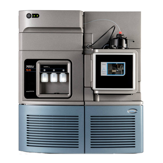
Page 18: Waters Xevo Tq Ms Overview
UPLC™/MS/MS analyses in quantitative and qualitative applications, it can ® operate at fast acquisition speeds compatible with UltraPerformance LC The Xevo TQ MS is fitted with the electrospray ionization (ESI) source. For mass spectrometer specifications, see the Waters Xevo TQ MS Site Preparation Guide. -
Page 19: Acquity ® Xevo Tq Ms Uplc/Ms Systems
® ACQUITY Xevo TQ MS UPLC/MS systems ® The Waters Xevo TQ MS is compatible with the ACQUITY UPLC systems; if you are not using an ACQUITY UPLC system, refer to the documentation relevant to your LC system. See “Non-ACQUITY devices for use with the Xevo TQ MS”... -
Page 20: Non-Acquity Devices For Use With The Xevo Tq Ms
Xevo TQ MS Sample manager Access door to the fluidics pump Binary solvent manager Non-ACQUITY devices for use with the Xevo TQ MS The following non-ACQUITY LC devices are validated for use with the Xevo TQ MS: • Waters Alliance 2695 separations module •... -
Page 21: Software And Data System
The Instrument Console functions independently of MassLynx software and does not recognize or control the data systems. See the Instrument Console system online Help for details. Waters Xevo TQ MS... -
Page 22: Ionization Techniques And Source Probes
(solvent evaporation). As solvent continues to evaporate, the charge density increases until the droplet surfaces eject ions (ion evaporation). The ions can be singly or multiply charged. The instrument can accommodate eluent flow rates of up to 2 mL/min. Waters Xevo TQ MS Overview... -
Page 23: Intellistart Fluidics System
IntelliStart Fluidics system Overview The IntelliStart Fluidics system is a solvent delivery system built into the mass spectrometer. It delivers sample directly to the MS probe in one of three ways: • From the LC column. • From three integral reservoirs. Use standard reservoir bottles (30 mL) for instrument setup and calibration. -
Page 24: System Components
You can set IntelliStart configuration requirements in the Instrument Console. You can edit the parameters, frequency, and extent of the automation. See the mass spectrometer’s online Help for further details on IntelliStart software and operation of the instrument’s solvent delivery system. Waters Xevo TQ MS Overview... -
Page 25: Ion Optics
Ion optics The mass spectrometer’s ion optics operate as follows: Samples from the LC or instrument’s solvent delivery system are introduced at atmospheric pressure into the ionization source. The ions pass through the sample cone into the vacuum system. The ions pass through the transfer optics to the first quadrupole where they can be filtered according to their mass-to-charge ratio (m/z). -
Page 26: Ms Operating Modes
In SIR and MRM modes, neither quadrupole is scanned, therefore no Note: spectrum (intensity versus mass) is produced. The data obtained from SIR or MRM analyses derive from the chromatogram plot (specified mass intensity versus time). 1-10 Waters Xevo TQ MS Overview... -
Page 27: Ms/Ms Operating Modes
MS/MS operating modes In SIR and MRM modes, neither quadrupole is scanned, so no spectrum Note: (intensity versus mass) is produced. The following table shows the MS/MS operating modes. MS/MS operating modes Operating mode Collision cell Product Static (at Pass all masses Scanning (daughter) ion precursor mass) -
Page 28: Product (Daughter) Ion Mode
Identifying product ions for use in MRM transitions. – Optimizing CID tuning conditions to maximize the yield of a specific product ion to be used in MRM analysis. • Structural elucidation (for example, peptide sequencing). 1-12 Waters Xevo TQ MS Overview... -
Page 29: Precursor (Parent) Ion Mode
Precursor (parent) ion mode Precursor ion mode Collision cell Scanning Pass all masses Static (at product mass) Typical application You typically use the precursor ion mode for structural elucidation—that is, to complement or confirm product scan data—by scanning for all the precursors of a common product ion. -
Page 30: Constant Neutral Loss Mode
ScanWave daughter scan mode This mode is very similar to conventional product ion mode in that you can specify an ion of interest for fragmentation in the collision cell, thus yielding 1-14 Waters Xevo TQ MS Overview... -
Page 31: Leak Sensors
1-12. Leak sensors Leak sensors in the drip trays of the Xevo TQ MS continuously monitor the instrument for leaks. A leak sensor stops system flow when its optical sensor detects about 1.5 mL of accumulated leaked liquid in its surrounding reservoir. -
Page 32: Rear Panel
External Connections 1 External Connections 2 and outputs Auxiliary 10MB Activity /100MB Collision cell gas inlet Source vacuum Power connection TP03118 Turbo vacuum Roughing pump relay switch Pilot valve port Source vent Nitrogen inlet 1-16 Waters Xevo TQ MS Overview... - Page 33 Preparing the Mass Spectrometer for Operation This chapter describes how to start and shut down the mass spectrometer. Contents Topic Page Starting the mass spectrometer Preparing the IntelliStart Fluidics system Rebooting the mass spectrometer Leaving the mass spectrometer ready for operation Emergency shutdown of the mass spectrometer...
-
Page 34: Preparing The Mass Spectrometer For Operation
Starting the mass spectrometer ® This instrument is compatible with the ACQUITY UPLC system; if you are not using an ACQUITY UPLC system, refer to the documentation relevant to the system you are using. See “Non-ACQUITY devices for use with the Xevo TQ MS”... - Page 35 Power-on the ACQUITY UPLC system workstation, and log in before powering-on the other instruments. Press the power switch on the top, left-hand side of the mass spectrometer and ACQUITY instruments. Each system instrument “beeps” and runs a series of startup Result: tests.
-
Page 36: Verifying The Instrument's State Of Readiness
Verifying the instrument’s state of readiness When the mass spectrometer is in good operating condition, the power and Operate LEDs show constant green. You can view any error messages in IntelliStart software. Monitoring the mass spectrometer LEDs Light-emitting diodes on the mass spectrometer indicate its operational status. -
Page 37: Running The Mass Spectrometer At High Flow Rates
To optimize ® desolvation, and thus sensitivity, run the ACQUITY Xevo TQ MS system at appropriate gas flows and desolvation temperatures. IntelliStart software automatically sets these parameters when you enter a flow rate, according to the following table. - Page 38 To install the reservoir bottles The reservoir bottles can be contaminated with Warning: biohazardous and/or toxic materials. Always wear chemical-resistant, powder-free gloves while performing this procedure. Remove the reservoir bottle caps. Screw the reservoir bottles onto the mass spectrometer as shown below. Reservoir bottle Preparing the Mass Spectrometer for Operation...
-
Page 39: Purging The Infusion Pump
To install the low-volume vials The reservoir bottles can be contaminated with Warning: biohazardous and/or toxic materials. Always wear chemical-resistant, powder-free gloves while performing this procedure. If a standard reservoir bottle is fitted, remove it. Screw the low-volume adaptors into the manifold, and finger tighten them. -
Page 40: Rebooting The Mass Spectrometer
Rebooting the mass spectrometer The reset button shuts down the electronics momentarily and causes the mass spectrometer to reboot. Reboot the mass spectrometer when either of these conditions applies: • The MassLynx software fails to initialize. • Immediately following a software upgrade. To reboot the mass spectrometer Open the mass spectrometer’s front, left-hand door. -
Page 41: Leaving The Mass Spectrometer Ready For Operation
Leaving the mass spectrometer ready for operation Leave the mass spectrometer in Operate mode except in the following cases: • When performing routine maintenance • When changing the source • When leaving the mass spectrometer unused for a long period In these instances, put the mass spectrometer in Standby mode, see the online Help for details. - Page 42 2-10 Preparing the Mass Spectrometer for Operation...
- Page 43 Preparing the ESI Source This chapter describes how to prepare the mass spectrometer for use. Contents Topic Page ESI mode...
-
Page 44: Preparing The Esi Source
ESI mode To run ESI, you must fit the ESI probe to the source enclosure. The following sections explain how to install and remove the ESI probe. Installing the ESI probe Required material Chemical-resistant, powder-free gloves To install the ESI probe The LC system connections, ESI probe, and source can Warning: be contaminated with biohazardous and/or toxic materials. - Page 45 With the probe label facing you, carefully slide the ESI probe into the hole in the probe adjuster assembly, ensuring that the probe location dowel aligns with the location hole of the probe adjuster assembly. ESI probe location dowel Location hole of the probe adjuster assembly TP03129 ESI mode...
- Page 46 ESI probe, mounted on the source enclosure Vernier probe adjuster ESI probe Probe locking ring ESI probe cable Vertical probe High voltage connector adjuster Source window Source enclosure release TP03128 To avoid nitrogen leakage, fully tighten the probe Caution: locking ring. Tighten the probe locking ring to secure the probe in place.
- Page 47 If you are replacing the tubing supplied with the Requirement: instrument, you must minimize the length of the tube connecting the diverter valve to the ESI probe. Doing so minimizes delays and dispersion. Tubing connection between the diverter valve and the ESI probe The other plumbing connections are omitted for clarity.
-
Page 48: Removing The Esi Probe
Removing the ESI probe Required material Chemical-resistant, powder-free gloves To remove the ESI probe The LC system connections, ESI probe, and source can Warning: be contaminated with biohazardous and/or toxic materials. Always wear chemical-resistant, powder-free gloves while performing this procedure. To avoid electric shock, ensure that the instrument is Warning: prepared for working on the source before commencing this procedure. -
Page 49: Maintenance Procedures
Maintenance Procedures This chapter provides the maintenance guidelines and procedures necessary to maintain the instrument’s performance. Keep to a maintenance schedule, and perform maintenance as required and described in this chapter. Contents Topic Page Maintenance schedule Spare parts Troubleshooting with Connections Insight Safety and handling Preparing the instrument for working on the source Removal and refitting of the source enclosure... - Page 50 Contents (Continued) Topic Page Replacing the source assembly seals 4-75 Replacing the air filter 4-79 Maintenance Procedures...
-
Page 51: Maintenance Schedule
Maintenance schedule The following table lists periodic maintenance schedules that ensure optimum instrument performance. Maintenance schedule Procedure Frequency For information... Clean the instrument case. As required. page 4-15. Empty the nitrogen exhaust Check daily, empty as page 4-15. trap bottle. required. -
Page 52: Spare Parts
XDS35i Instruction Manual A730-01-880. Replace the air filter. Annually. page 4-79. Spare parts Replace only the parts mentioned in this document. For spare parts details, see the Waters Quality Parts Locator on the Waters Web site’s Services/Support page. Maintenance Procedures... -
Page 53: Troubleshooting With Connections Insight
Troubleshooting with Connections Insight ® Connections Insight is an intelligent device management (IDM) Web service that enables Waters to provide proactive service and support for the ® ACQUITY UPLC system. To use Connections Insight, a Waters technician must install its service agent software on your MassLynx workstation. In a client/server system, the service agent must also be installed on the computer from which you control the system. -
Page 54: Safety And Handling
Safety and handling Bear in mind the following safety considerations when performing maintenance procedures: The instrument components can be contaminated with Warning: biologically hazardous materials. Always wear chemical-resistant, powder-free gloves while handling the components. To prevent injury, always observe Good Laboratory Practices Warning: when handling solvents, changing tubing, or operating the instrument. -
Page 55: Preparing The Instrument For Working On The Source
In the Instrument Console, click Stop Flow to stop the LC flow or, if column flow is required, divert the LC flow to waste as follows: In the Instrument Console system tree, expand Xevo TQ MS Detector, Interactive Fluidics. Click Control Select Waste as the flow state. -
Page 56: Removal And Refitting Of The Source Enclosure
Removal and refitting of the source enclosure Removing the source enclosure from the instrument Required material Chemical-resistant, powder-free gloves To remove the source enclosure The source components can be contaminated with Warning: biohazardous and/or toxic materials. Always wear chemical-resistant, powder-free gloves while performing this procedure. -
Page 57: Fitting The Source Enclosure To The Instrument
Using both hands, grasp the source enclosure, and lift it vertically off the two supporting studs on the source adaptor housing. Supporting stud TP03164 Source enclosure Fitting the source enclosure to the instrument Required material Chemical-resistant, powder-free gloves To fit the source enclosure The source components can be contaminated with Warning: biohazardous and/or toxic materials. - Page 58 Close the source enclosure. Connect the probe adjuster and options cables (as required) to the instrument’s connectors. Slide closed the instrument’s source interface door. 4-10 Maintenance Procedures...
-
Page 59: Operating The Source Isolation Valve
Operating the source isolation valve You must close the source isolation valve to isolate the source from the instrument vacuum system for certain maintenance procedures. Required material Chemical-resistant, powder-free gloves To close the source isolation valve before starting a maintenance procedure The source components can be contaminated with Warning: biohazardous and/or toxic materials. - Page 60 Close the source isolation valve by moving its handle counterclockwise, to the vertical position. Isolation valve handle in closed position 4-12 Maintenance Procedures...
- Page 61 To open the source isolation valve after completing a maintenance procedure The source components can be contaminated with Warning: biohazardous and/or toxic materials. Always wear chemical-resistant, powder-free gloves while performing this procedure. To avoid puncture wounds, take great care while working Warning: with the source enclosure open, because the ESI probe tip is sharp.
-
Page 62: Removing O-Rings And Seals
Removing O-rings and seals When performing certain maintenance procedures, you must remove O-rings or seals from instrument components. An O-ring removal kit is provided with the instrument. O-ring removal kit Tool 1 Tool 2 To remove an O-ring When removing an O-ring or seal from a component, be Caution: careful not to scratch the component with the removal tool. -
Page 63: Cleaning The Instrument Case
Cleaning the instrument case Do not use abrasives or solvents to clean the instrument’s Caution: case. Use a soft cloth, dampened with water, to clean the outside surfaces of the mass spectrometer. Emptying the nitrogen exhaust trap bottle Inspect the nitrogen exhaust trap bottle in the instrument’s exhaust line, daily and empty it before it is more than approximately 10% full. - Page 64 Required materials Chemical-resistant, powder-free gloves To empty the nitrogen exhaust trap bottle In the Instrument Console, click Stop Flow to stop the LC flow. Pull the source enclosure release (located at the bottom, right-hand side) outwards, and swing open the enclosure. The waste liquid in the nitrogen exhaust trap Warning: bottle comprises ACQUITY UPLC solvents and analytes.
-
Page 65: Inspecting The Varian Roughing Pump Oil Level
Inspecting the Varian roughing pump oil level To ensure correct operation of the Varian™ roughing pump, Caution: do not operate the pump with the oil level at less than 30% of the MAX level. This procedure is not required for an Edwards oil-free roughing pump. You must inspect the oil level while the roughing pump is Requirement: running. -
Page 66: Adding Oil To The Varian Roughing Pump
Adding oil to the Varian roughing pump If the roughing pump oil level is found to be low, you must add oil to the roughing pump. See “Inspecting the Varian roughing pump oil level” on page 4-17. Varian roughing pump Oil filler plug Oil level sight glass TP03159... - Page 67 To add oil to the roughing pump Vent and shut down the mass spectrometer (see the mass spectrometer’s online Help for details). 2. Allow the oil to settle in the pump. The pump oil can be contaminated with analyte Warning: accumulated during normal operation.
-
Page 68: Replacing The Varian Roughing Pump Oil And Oil Mist Filter
Replacing the Varian roughing pump oil and oil mist filter Change the roughing pump oil and oil mist filter annually. This procedure is not required for an Edwards oil-free roughing pump. Emptying the roughing pump oil Required materials • Chemical-resistant, powder-free gloves •... -
Page 69: Replacing The Oil Mist Filter
The roughing pump oil can be contaminated with Warning: biohazardous and/or toxic materials. Dispose of it according to local environmental regulations. Dispose of the roughing pump oil in accordance with local environmental regulations. Use the lint-free cloth to remove loose particles from the magnetic tip of the oil drain plug. - Page 70 Remove the oil mist canister cover from the oil mist canister. The cover can be tight and difficult to remove. Tip: Oil mist canister cover Spring Oil mist filter O-ring Remove the spring and oil mist filter from the canister. The oil mist filter can be contaminated with Warning: biohazardous and/or toxic materials.
-
Page 71: To Refill The Pump With Oil
To refill the pump with oil Required materials • Chemical-resistant, powder-free gloves • 8-mm Allen wrench • Funnel • 1-L bottle of Varian GP45 oil Refilling the pump with oil The roughing pump components can be contaminated Warning: with analyte accumulated during normal operation. Always wear chemical-resistant, powder-free gloves when performing this procedure. - Page 72 Ensure that the O-ring on the oil filler plug is clean and properly seated. To avoid oil leakage when fitting the oil filler plug to Caution: the roughing pump, • ensure that the plug is not cross threaded. • ensure that the O-ring is not pinched. •...
-
Page 73: Cleaning The Source Components
Cleaning the source components Clean the sample cone and cone gas nozzle when these conditions apply: • The sample cone and cone gas nozzle are visibly fouled. • LC and sample-related causes for decreased signal intensity have been dismissed. “Cleaning the sampling cone assembly” on page 4-26. -
Page 74: Cleaning The Sampling Cone Assembly
Cleaning the sampling cone assembly You can remove the sampling cone assembly (comprising the sample cone, O-ring, and cone gas nozzle) for cleaning without venting the instrument. Removing the sampling cone assembly from the source Required material Chemical-resistant, powder-free gloves To remove the sampling cone assembly from the source The source components can be contaminated with Warning:... - Page 75 Grasp the cone gas nozzle handle, and use it to rotate the sampling cone assembly 90 degrees, moving the handle from the vertical to the horizontal position. Sampling cone assembly Cone gas nozzle handle TP03131 Do not open the isolation valve at any time when the Caution: sampling cone assembly has been removed from the ion block assembly.
-
Page 76: Disassembling The Sampling Cone Assembly
Disassembling the sampling cone assembly Required material • Chemical-resistant, powder-free gloves • Combined 2.5-mm Allen wrench and cone extraction tool To disassemble the sampling cone assembly The sampling cone assembly can be contaminated with Warning: biohazardous and/or toxic materials. Always wear chemical-resistant, powder-free gloves while performing this procedure. - Page 77 The sample cone is fragile. Never place it on its tip; Caution: always place it on its flanged base. Rotate and lift the tool and collar to remove the sample cone from the cone gas nozzle. Remove the O-ring from the sample cone. Cone gas nozzle Cone gas nozzle handle O-ring...
-
Page 78: Cleaning The Sample Cone And Cone Gas Nozzle
The O-ring can be contaminated with Warning: biohazardous and/or toxic materials. Dispose of it according to local environmental regulations. If the O-ring shows signs of deterioration or damage, dispose of it in accordance with local environmental regulations. Unscrew and remove the PEEK cone gas nozzle handle from the cone gas nozzle. - Page 79 To clean the sample cone and cone gas nozzle The sample cone and cone gas nozzle can be Warning: contaminated with biohazardous and/or toxic materials. Always wear chemical-resistant, powder-free gloves while performing this procedure. Formic acid is extremely corrosive and toxic. Work Warning: with extreme care, use a fume hood and suitable protective equipment.
-
Page 80: Assembling The Sampling Cone Assembly
Inspect each component for persisting contamination. If contamination is present, do as follows: Use the wash bottle containing 1:1 methanol/water to rinse the component over the large beaker. Blow-dry the component with inert, oil-free gas. Inspect each component for persisting contamination. If contamination is present, dispose of the component, and obtain a new one before reassembling the sampling cone assembly. -
Page 81: Fitting The Sampling Cone Assembly To The Source
Carefully fit the sample cone into the cone gas nozzle. Fit the O-ring into the groove created between the sample cone and cone gas nozzle. (Fit a new O-ring if the old one has been disposed of.) Fitting the sampling cone assembly to the source Required material Chemical-resistant, powder-free gloves To fit the sampling cone assembly to the source... - Page 82 Hold the sampling cone assembly so that the cone gas nozzle handle is oriented horizontally and at the top, and then slide the sampling cone assembly into the ion block assembly. Ion block assembly TP03132 Sampling cone assembly Grasp the cone gas nozzle handle and use it to rotate the sampling cone assembly 90 degrees, moving the handle downward from the horizontal to the vertical position.
-
Page 83: Cleaning The Extraction Cone
Cleaning the extraction cone Clean the ion block and extraction cone when cleaning the sample cone and cone gas nozzle fails to increase signal sensitivity. You must remove the ion block assembly from the source assembly to clean the extraction cone. Removing the ion block assembly from the source assembly Required materials •... - Page 84 Use the combined 2.5-mm Allen wrench and cone extraction tool to unscrew the 4 captive ion block assembly securing screws. Ion block assembly securing screws TP03130 Remove the ion block assembly from the PEEK ion block support. PEEK ion block support Ion block assembly TP03130...
-
Page 85: Removing The Extraction Cone From The Ion Block
Removing the extraction cone from the ion block Required materials • Chemical-resistant, powder-free gloves • Combined 2.5-mm Allen wrench and cone extraction tool To remove the extraction cone from the ion block The ion block components can be contaminated with Warning: biohazardous and/or toxic materials. -
Page 86: Cleaning The Extraction Cone
Caution: • Take great care not to damage the extraction cone aperture when removing the extraction cone from the ion block. • The extraction cone is fragile. Never place it on its tip; always place it on its flanged base. Remove the extraction cone from the ion block. - Page 87 • Ultrasonic bath. • Source of oil-free, inert gas (for example, nitrogen) for drying (air-drying optional). • Wash bottle containing HPLC-grade (or better) 1:1 methanol/water. • Large beaker. To clean the extraction cone The extraction cone can be contaminated with Warning: biohazardous and/or toxic materials.
-
Page 88: Fitting The Extraction Cone To The Ion Block
To avoid recontaminating the extraction cone, wear Caution: clean, chemical-resistant, powder-free gloves for the rest of this procedure. Carefully remove the extraction cone from the vessel, and blow-dry it using inert, oil-free gas. Inspect the extraction cone for persisting contamination. If contamination is present, do as follows: Use the wash bottle containing 1:1 methanol/water to rinse the extraction cone over the large beaker. -
Page 89: Fitting The Ion Block Assembly To The Source Assembly
Rotate the 2 PEEK extraction cone retainer clips to secure the extraction cone, then use the combined 2.5-mm Allen wrench and cone extraction tool to tighten the retainer clip securing screws. Fitting the ion block assembly to the source assembly Required materials •... -
Page 90: Cleaning The Ion Block Assembly
Cleaning the ion block assembly Clean the ion block assembly if cleaning the sample cone, cone gas nozzle, and extraction cone fails to increase signal sensitivity. Disassembling the source ion block assembly Required materials • Chemical-resistant, powder-free gloves • Combined 2.5-mm Allen wrench and cone extraction tool •... - Page 91 Grasp the cone gas nozzle handle and use it to rotate the sampling cone assembly through 90 degrees. To ensure correct operation of the ion block assembly Caution: after reassembly, • do not remove the sampling cone assembly retaining blocks. •...
- Page 92 Grasp the isolation valve and pull it out of the ion block. Isolation valve O-ring Use the O-ring removal kit to carefully remove the isolation valve O-ring (see “Removing O-rings and seals” on page 4-14). The isolation valve O-ring can be contaminated Warning: with biohazardous and/or toxic materials.
- Page 93 10. Use the combined 2.5-mm Allen wrench and cone extraction tool to loosen the captive PEEK terminal block securing screw. PEEK terminal block securing screw To avoid damaging the heater cartridge assembly Caution: wires, do not bend or twist them when removing the assembly from the ion block.
- Page 94 13. Use the O-ring removal kit to carefully remove the cover seal from the ion block (see also “Removing O-rings and seals” on page 4-14). Cover seal Cone gas O-ring 14. Use the O-ring removal kit to carefully remove the cone gas O-ring from the ion block.
- Page 95 16. Insert the combined 2.5-mm Allen wrench and cone extraction tool through the hole in the ion block blanking plug, and then unscrew and remove the ion block blanking plug and associated seal. Blanking plug Combined 2.5-mm Allen wrench and cone extraction tool The blanking plug seal can be contaminated with Warning: biohazardous and/or toxic materials.
- Page 96 18. Use the combined 2.5-mm Allen wrench and cone extraction tool to remove the captive screws securing the 2 PEEK extraction cone retainer clips. Securing screw Retainer clip Extraction cone Caution: • Take great care not to damage the extraction cone aperture when removing the extraction cone from the ion block.
-
Page 97: Cleaning The Ion Block Components
20. Remove the extraction cone handle insulator from the extraction cone handle. 21. Remove the extraction cone seal from the ion block. Extraction cone seal Cleaning the ion block components Required materials • Chemical-resistant, powder-free gloves. • Appropriately sized glass vessels in which to completely immerse components when cleaning. - Page 98 To clean the ion block components The ion block components can be contaminated with Warning: biohazardous and/or toxic materials. Always wear chemical-resistant, powder-free gloves while performing this procedure. Formic acid is extremely corrosive and toxic. Work Warning: with extreme care, use a fume hood and suitable protective equipment.
-
Page 99: Assembling The Source Ion Block Assembly
The components can be contaminated with Warning: biohazardous and/or toxic materials. Dispose of them according to local environmental regulations. Inspect each component for persisting contamination. If contamination is present, dispose of the component, and obtain a new one before reassembly. Assembling the source ion block assembly Required materials •... - Page 100 Fit the blanking plug seal to the ion block blanking plug. (Fit a new seal if the old one has been disposed of.) Fit the blanking plug to the ion block and finger tighten it. Insert the combined 2.5-mm Allen wrench and cone extraction tool through the hole in the blanking plug and use it to fully tighten the plug.
-
Page 101: Cleaning The Source Hexapole Assembly
18. Hold the sampling cone assembly so that the cone gas nozzle handle is oriented horizontally and at the top, and then slide the sampling cone assembly into the ion block assembly. 19. Grasp the sampling cone assembly handle, and use it to rotate the sampling cone assembly through 90 degrees. - Page 102 Use the 3-mm Allen wrench to unscrew and remove the 4 screws securing the PEEK ion block support to the adaptor housing. Adaptor housing PEEK ion block support Hexapole assembly Securing screws Remove the PEEK ion block support from the adaptor housing. Use the O-ring removal kit to carefully remove all the O-rings from the PEEK ion block support (see “Removing O-rings and seals”...
-
Page 103: Cleaning The Hexapole Assembly
To avoid damage when removing the hexapole assembly Caution: from the adaptor housing: • avoid scratching the internal surfaces of the adaptor block. • do not compress the hexapole rods. Carefully grasp the source hexapole assembly and remove it from the adaptor housing. - Page 104 Insert one end of the hook into one of the holes on the hexapole assembly’s rear support ring. To avoid vibration damage to the hexapole assembly, Caution: ensure that the bottom of the assembly is not in contact with the bottom of the glass vessel.
-
Page 105: Fitting The Hexapole Assembly, Peek Ion Block Support, And Ion Block Assembly To The Source Assembly
Inspect the hexapole assembly for persisting contamination, If contamination is present, do as follows: Use the wash bottle containing methanol to rinse the source hexapole assembly over the large beaker. Blow-dry the hexapole assembly with inert, oil-free gas. Use the small flat-blade screwdriver to ensure that the hexapole assembly screws are tight. - Page 106 Fit the O-rings to the PEEK ion block support. Fit new O-rings if any of the old O-rings were disposed of. To fit an O-ring in its groove, start fitting the O-ring at the notch in Tip: the groove, and then progressively work the ring into the groove, in either direction from the notch.
-
Page 107: Replacing The Esi Probe Tip And Gasket
Replacing the ESI probe tip and gasket Replace the ESI probe tip if a blockage occurs in the internal metal sheathing through which the stainless steel capillary passes or if the probe tip is damaged. Removing the ESI probe tip and gasket Required materials •... - Page 108 Use the 10-mm wrench to remove the probe tip. 10-mm wrench Probe tip If the probe tip is difficult to remove, use the 7-mm wrench in Tip: conjunction with the 10-mm wrench. 7-mm wrench 10-mm wrench Probe tip 4-60 Maintenance Procedures...
- Page 109 Remove the metal gasket from the probe tip. Metal gasket The probe tip and metal gasket can be Warning: contaminated with biohazardous and/or toxic materials. Dispose of them according to local environmental regulations. If the probe tip and metal gasket are damaged, dispose of them in accordance with local environmental regulations.
-
Page 110: Fitting The Esi Probe Tip And Gasket
Fitting the ESI probe tip and gasket Required materials • Chemical-resistant, powder-free gloves • 10-mm wrench To fit the ESI probe tip and gasket The probe and source components can be contaminated Warning: with biohazardous and/or toxic materials. Always wear chemical-resistant, powder-free gloves while performing this procedure. -
Page 111: Replacing The Esi Probe Sample Capillary
Replacing the ESI probe sample capillary Replace the stainless steel sample capillary in the ESI probe if it becomes blocked and cannot be cleared, or if it becomes contaminated or damaged. Removing the existing capillary Required materials • Chemical-resistant, powder-free gloves •... - Page 112 Use the combined 2.5-mm Allen wrench and cone extraction tool to remove the 3 probe end-cover retaining screws. End-cover retaining screws Remove the end-cover from the probe assembly. Nebulizer adjuster knob End-cover Unscrew and remove the nebulizer adjuster knob. 4-64 Maintenance Procedures...
- Page 113 Use the 10-mm wrench to remove the probe tip. 10-mm wrench Probe tip If the probe tip is difficult to remove, use the 7-mm wrench in Tip: conjunction with the 10-mm wrench. 7-mm wrench 10-mm wrench Probe tip Replacing the ESI probe sample capillary 4-65...
- Page 114 Remove the metal gasket from the probe tip. Metal gasket Remove the PEEK union/UNF coupling assembly and capillary from the probe. PEEK union/UNF coupling assembly Capillary Unscrew and remove the knurled collar from the UNF coupling. PEEK union UNF coupling Locknut Knurled collar Conductive sleeve...
-
Page 115: Installing The New Capillary
10. Use the 7-mm wrench to loosen the locknut. Use the 8-mm wrench, to steady the UNF coupling when loosening Tip: the locknut. 11. Unscrew the PEEK union from the UNF coupling (this connection is finger-tight only). Ferrule PTFE liner sleeve 12. - Page 116 • PTFE liner tube • Conductive sleeve • Red, PEEK tubing • Sharp knife To install the new capillary The probe and source components can be contaminated Warning: with biohazardous and/or toxic materials. Always wear chemical-resistant, powder-free gloves while performing this procedure.
- Page 117 Use the needle-nose pliers to slide a new liner sleeve and ferrule onto the capillary. Insert the capillary in the PEEK union, and ensure that it is fully seated. Screw the UNF coupling into the PEEK union, finger-tight only. Gently tug on the capillary, testing to ensure that it stays in place. Use the 7-mm wrench to tighten the locknut against the PEEK union until the union can no longer be twisted.
- Page 118 15. Carefully push the PEEK union/UNF coupling assembly and capillary into the probe assembly so that the locating pin on the UNF coupling is fully engaged in the locating slot at the head of the probe assembly. UNF coupling locating pin Probe assembly locating slot 16.
-
Page 119: Replacing The Ion Block Source Heater
Replacing the ion block source heater Replace the ion block source heater if it fails to heat when the instrument is pumped down (evacuated). Required materials • Chemical-resistant, powder-free gloves • Needle-nose pliers • Combined 2.5-mm Allen wrench and cone extraction tool •... - Page 120 Use the combined 2.5-mm Allen wrench and cone extraction tool to loosen the 2 captive screws securing the ion block cover plate. Ion block cover plate securing screw Ion block cover plate Remove the ion block cover plate. 4-72 Maintenance Procedures...
- Page 121 Use the combined 2.5-mm Allen wrench and cone extraction tool to remove the 2 screws securing the heater wires to the PEEK terminal block. Heater cartridge wire securing screws PEEK terminal block Use the needle-nose pliers to carefully swing the ring terminal tags out of the terminal block.
- Page 122 Use the needle-nose pliers to gently grasp the heat-shrink tubing on the heater cartridge assembly and slide the assembly out of the ion block. Heat-shrink tubing Heater cartridge assembly Dispose of the heater cartridge assembly. To avoid damaging the heater cartridge assembly Caution: wires, do not bend or twist them when fitting the assembly to the ion block.
-
Page 123: Replacing The Source Assembly Seals
Replacing the source assembly seals To avoid excessive leakage of solvent vapor into the Warning: laboratory atmosphere, the seals listed below must be renewed, at intervals of no greater than 1 year, exactly as described in this section. To avoid excessive leakage of solvent vapor into the laboratory atmosphere, the following seals must be renewed at intervals of no greater than 1 year: •... - Page 124 To remove the probe adjuster assembly probe and source enclosure seals The source components can be contaminated with Warning: biohazardous and/or toxic materials. Always wear chemical-resistant, powder-free gloves while performing this procedure. Remove the source enclosure from the instrument (see “Removing the source enclosure from the instrument”...
-
Page 125: Fitting The New Source Enclosure And Probe Adjuster Assembly Probe Seals
• Desolvation gas seal • Auxiliary gas seal Nebulizer gas seal Desolvation gas Auxiliary gas seal seal Source enclosure seal TP03164 The seals can be contaminated with biohazardous Warning: and/or toxic materials. Dispose of them according to local environmental regulations. Dispose of all the seals in accordance with local environmental regulations. - Page 126 To fit the new source enclosure and probe adjuster assembly probe seals The source components can be contaminated with Warning: biohazardous and/or toxic materials. Always wear chemical-resistant, powder-free gloves while performing this procedure. Ensure that all the grooves for seals are free from dirt and debris. If contamination is present, use 1:1 methanol/water, applied to a Tip: lint-free cloth, to carefully clean the grooves.
-
Page 127: Replacing The Air Filter
Replacing the air filter You must replace the air filter annually. Required materials • Needle-nose pliers • New filter To replace the air filter Open the access door to the fluidics pump. Unscrew the captive thumbscrew on the filter cover. Thumbscrew Filter cover Replacing the air filter... - Page 128 Remove the filter cover from the instrument. Filter Filter cover Lift the filter, vertically, from the its slot in the instrument. If necessary, use the needle-nose files to grasp the filter. Tip: Dispose of the filter. Fit the new filter into the instrument. Fit the filter cover to the instrument.
- Page 129 Replacing the air filter 4-81...
- Page 130 4-82 Maintenance Procedures...
- Page 131 Safety Advisories Waters instruments display hazard symbols designed to alert you to the hidden dangers of operating and maintaining the instruments. Their corresponding user guides also include the hazard symbols, with accompanying text statements describing the hazards and telling you how to avoid them.
-
Page 132: A Safety Advisories
Heed all warnings when you install, repair, and operate Waters instruments. Waters assumes no liability for the failure of those who install, repair, or operate its instruments to comply with any safety precaution. -
Page 133: Specific Warnings
The following warnings can appear in the user manuals of particular instruments and on labels affixed to them or their component parts. Burst warning This warning applies to Waters instruments fitted with nonmetallic tubing. Pressurized nonmetallic, or polymer, tubing can burst. Warning: Observe these precautions when working around such tubing: •... - Page 134 Also ensure a gas-fail connection is connected to the LC system so that the LC solvent flow stops if the nitrogen supply fails. Mass spectrometer shock hazard This warning applies to all Waters mass spectrometers. To avoid electric shock, do not remove the mass spectrometer’s Warning: protective panels.
-
Page 135: Caution Symbol
Biohazard warning This warning applies to Waters instruments that can be used to process material that might contain biohazards: substances that contain biological agents capable of producing harmful effects in humans. Waters instruments and software can be used to analyze or... -
Page 136: Warnings That Apply To All Waters Instruments
Warnings that apply to all Waters instruments When operating this device, follow standard quality control procedures and the equipment guidelines in this section. Attention: Changes or modifications to this unit not expressly approved by the party responsible for compliance could void the user’s authority to operate the equipment. - Page 137 • Keine Schläuche verwenden, die stark geknickt oder überbeansprucht sind. • Nichtmetallische Schläuche nicht für Tetrahydrofuran (THF) oder konzentrierte Salpeter- oder Schwefelsäure verwenden. • Durch Methylenchlorid und Dimethylsulfoxid können nichtmetallische Schläuche quellen; dadurch wird der Berstdruck des Schlauches erheblich reduziert. Warnings that apply to all Waters instruments...
- Page 138 Attenzione: fare attenzione quando si utilizzano tubi in materiale polimerico sotto pressione: • Indossare sempre occhiali da lavoro protettivi nei pressi di tubi di polimero pressurizzati. • Spegnere tutte le fiamme vive nell'ambiente circostante. • Non utilizzare tubi eccessivamente logorati o piegati. •...
- Page 139 농축 질산 또는 황산과 함께 사용하지 마십시오. • 염화 메틸렌(Methylene chloride) 및 디메틸술폭시드(Dimethyl sulfoxide)는 비금속 튜브를 부풀려 튜브의 파열 압력을 크게 감소시킬 수 있으므로 유의하십시오. 警告:圧力のかかったポリマーチューブを扱うときは、注意してください。 • 加圧されたポリマーチューブの付近では、必ず保護メガネを着用してください。 • 近くにある火を消してください。 • 著しく変形した、または折れ曲がったチューブは使用しないでください。 • 非金属チューブには、テトラヒドロフラン(THF)や高濃度の硝酸または硫酸などを流 さないでください。 • 塩化メチレンやジメチルスルホキシドは、非金属チューブの膨張を引き起こす場合が あり、その場合、チューブは極めて低い圧力で破裂します。 Warnings that apply to all Waters instruments...
- Page 140 Warning: The user shall be made aware that if the equipment is used in a manner not specified by the manufacturer, the protection provided by the equipment may be impaired. Attention: L’utilisateur doit être informé que si le matériel est utilisé d’une façon non spécifiée par le fabricant, la protection assurée par le matériel risque d’être défectueuses.
-
Page 141: Electrical And Handling Symbols
Electrical and handling symbols Electrical symbols These can appear in instrument user manuals and on the instrument’s front or rear panels. Electrical power on Electrical power off Standby Direct current Alternating current Protective conductor terminal Frame, or chassis, terminal Fuse Recycle symbol: Do not dispose in municipal waste. -
Page 142: Handling Symbols
Handling symbols These handling symbols and their associated text can appear on labels affixed to the outer packaging of Waters instrument and component shipments. Keep upright! Keep dry! Fragile! Use no hooks! A-12 Safety Advisories... - Page 143 Materials of Construction and Compliant Solvents To confirm the integrity of the source exhaust Warning: system, you must address any safety issues raised by the contents of this Appendix. Contents Topic Page Preventing contamination Items exposed to solvent Solvents used to prepare mobile phases...
-
Page 144: B Materials Of Construction And Compliant Solvents
Preventing contamination For information on preventing contamination, refer to Controlling Contamination in LC/MS Systems (part number 715001307). Visit www.waters.com. Items exposed to solvent The items that appear in the following table can be exposed to solvent. You must evaluate the safety issues if the solvents used in your application differ from the solvents typically used with these items. -
Page 145: Solvents Used To Prepare Mobile Phases
Items exposed to solvent (Continued) Item Material Trap bottle push-in fittings Nitrile butadiene rubber, stainless steel, polybutylene terephthalate, and polyoxymethylene Solvents used to prepare mobile phases These solvents are the most common ingredients used to prepare mobile phases for reverse-phase LC/MS (API): •... - Page 146 Materials of Construction and Compliant Solvents...
- Page 147 The mass spectrometer is heavy. To avoid injury, use Warning: suitable machinery and the supplied harness to lift it. Caution: • Contact Waters Technical Service before moving the instrument. • If you must transport the mass spectrometer, or remove it from service, contact Waters Technical Service for recommended cleaning, flushing, and packaging procedures.
-
Page 148: C External Connections
Mass spectrometer external wiring and vacuum connections The instrument’s rear panel connectors are shown below. Mass spectrometer rear panel connectors Shielded Ethernet LA N External Connections 1 Service Bus EPC Com Port External Connections 2 Video Output OUT - Event inputs External Connections 1 External Connections 2 and outputs... -
Page 149: Connecting The Varian Oil-Filled Roughing Pump
NW25 center rings (included in the installation kit) • NW25 clamps (included in the installation kit) • 12.7-mm clear PVC exhaust tubing (included in the Waters Rotary Pump Kit) • PVC hose clamps (included in the Waters Rotary Pump Kit) - Page 150 • 1-inch ID vacuum hose (included in the Waters Rotary Pump Kit) • PTFE drip tray To connect the roughing pump The pump and its connections can be Warning: contaminated with biohazardous and/or toxic materials. Always wear chemical-resistant, powder-free gloves when performing this procedure.
- Page 151 Place the PTFE drip tray on the floor, within 5 feet of the instrument. The roughing pump is heavy. To avoid injury, at least Warning: two people must lift the pump. Place the pump on the PTFE drip tray. Attach the NW25 tee to the roughing pump inlet flange using an NW25 center ring, and then secure the connection with an NW25 clamp, using the 7-mm nut driver to install the clamp.
- Page 152 Connect the free ends of the two lengths of vacuum hose to the two, 1-inch OD, straight, vacuum ports on the mass spectrometer’s rear panel. Install 2 clamps on each hose end. To avoid gas leaks, use the sharp knife to cut the PVC Caution: exhaust tubing squarely (that is, perpendicular to its horizontal axis).
-
Page 153: Making The Electrical Connections To The Varian Oil-Filled Roughing Pump
Making the electrical connections to the Varian oil-filled roughing pump Roughing pump connections LA N External Connections 1 Service Bus EPC Com Port External Connections 2 Video Output OUT - External Connections 1 External Connections 2 Auxiliary Roughing pump 10MB Activity /100MB d.c. -
Page 154: Connecting The Edwards Oil-Free Roughing Pump
Chemical-resistant, powder-free gloves • 7-mm nut driver • Sharp knife • Elbow (included in the Waters Rotary Pump Kit) • NW25 tee (included in the installation kit) • NW25 center rings (included in the installation kit) • NW25 clamps (included in the installation kit) •... - Page 155 Pump Kit) • PVC hose clamps (included in the Waters Rotary Pump Kit) • 1-inch ID vacuum hose (included in the Waters Rotary Pump Kit) To connect the oil-free roughing pump The pump and its connections can be Warning: contaminated with biohazardous and/or toxic materials.
- Page 156 Attach the NW25/NW40 adaptor to the roughing pump inlet flange using an NW40 center ring, and then secure the connection with an NW40 clamp, using the 7-mm nut driver to install the clamp. Attach the NW25 tee to the NW25/NW40 adaptor using an NW25 center ring, and then secure the connection with an NW25 clamp, using the 7-mm nut driver to install the clamp.
- Page 157 Install 2 clamps on each hose end. To avoid gas leaks, use the sharp knife to cut the PVC Caution: exhaust tubing squarely (that is, perpendicular to its horizontal axis). Connect the 12.7-mm clear PVC exhaust tubing to the roughing pump exhaust port NW25 nozzle fitting, and secure the tubing with a hose clamp.
- Page 158 Making the electrical connections for the Edwards oil-free roughing pump Roughing pump connections LA N External Connections 1 Service Bus EPC Com Port External Connections 2 Video Output OUT - External Connections 1 External Connections 2 Auxiliary Roughing pump 10MB Activity /100MB d.c.
-
Page 159: Connecting To The Nitrogen Gas Supply
Required materials • Chemical-resistant, powder-free gloves • 6-mm PTFE tubing (included in the Waters Rough Pump Connect Kit) • Nitrogen regulator To connect the nitrogen gas supply Connect one end of the 6-mm PTFE tubing to the nitrogen inlet port on the rear of the instrument. - Page 160 Connect the free end of the 6-mm PTFE tubing to the nitrogen regulator. The nitrogen must be dry and oil-free, with a purity of at Requirement: least 95%. Set the nitrogen regulator to 600 to 690 kPa (6.0 to 6.9 bar, 90 to 100 psi).
-
Page 161: Connecting To The Collision Cell Gas Supply
Connecting to the collision cell gas supply Required materials • Chemical-resistant, powder-free gloves • 11-mm wrench ® • 1/8-inch Swagelok nut and ferrule • 1/8-inch stainless steel tube (supplied with the mass spectrometer) • Argon regulator (not supplied) To connect the collision cell gas supply Use the 1/8-inch Swagelok nut and ferrule to connect the 1/8-inch stainless steel tube to the collision cell gas inlet on the rear of the mass spectrometer (see the figure on... -
Page 162: Connecting The Nitrogen Exhaust Line
Chemical-resistant, powder-free gloves • Sharp knife • Nitrogen exhaust trap bottle • 6-mm, 10-mm, and 12-mm PTFE tubing (included in the Waters Rough Pump Connect Kit) ® • snoop (or equivalent) leak detector liquid To connect the nitrogen exhaust line Warning: •... - Page 163 Nitrogen exhaust trap bottle From instrument To laboratory pilot valve port exhaust port From instrument exhaust connection Nitrogen exhaust trap bottle TP03164 To avoid gas leaks, use the sharp knife to cut the PTFE Caution: tubing squarely (that is, perpendicular to its horizontal axis). Cut a length of 6-mm tubing long enough to connect the instrument to the nitrogen exhaust trap bottle.
- Page 164 Connect one end of the tubing to the exhaust port on the instrument’s rear panel. Connect the free end of the tubing to the inlet port on the nitrogen exhaust trap bottle. To avoid gas leaks, use the sharp knife to cut the PTFE Caution: tubing squarely (that is, perpendicular to its horizontal axis).
-
Page 165: Connecting The Liquid Waste Line
Connecting the liquid waste line Required materials • Chemical-resistant, powder-free gloves • Waste container To connect the liquid waste line The waste line and connection can be contaminated Warning: with biologically hazardous materials. Always wear chemical-resistant, powder-free gloves while performing this procedure. - Page 166 To prevent leakage of biologically hazardous Warning: materials, • do not crimp or bend drain line. A crimp or bend can impede flow to the waste container. • empty the waste container before the lower end of the drain tube is covered by waste solvent. Route the waste line to the waste container.
-
Page 167: Connecting The Workstation
Connecting the workstation Before connecting the workstation to the instrument, set up the workstation according to its accompanying instructions. Locate the workstation within 5 meters (16 feet) of the instrument. Use shielded network cables with the mass spectrometer to Requirement: ensure compliance with FCC limits. -
Page 168: Connecting Ethernet Cables
Connecting Ethernet cables Use shielded network cables with the mass spectrometer to Requirement: ensure compliance with FCC limits. To make Ethernet connections Connect one end of one shielded Ethernet cable to the network switch, and then connect the other end to the Ethernet card on the ®... - Page 169 Input and output connector locations LA N External Connections 1 Service Bus External connections identification tables EPC Com Port External Connections 2 Video Output OUT - External connections 1 External Connections 1 External connections 2 External Connections 2 System Activity Input/output signal connector configuration Input/output signal connectors C-23...
- Page 170 External connections 1 Function Rating Event In 1+, digital signal, optimum +3.3V +5 V max +5V Event In 1-, digital ground, 0V Not used Event In 2+, digital signal, optimum +3.3V +5 V max +5V Event In 2-, digital ground, 0V Not used Not used CE Interlock Out, common...
-
Page 171: Making Signal Connections
Making signal connections Mass spectrometer signal connections Signal connections Description Analog (Out) Used for analog chart output functionality. The output voltage range is 0 to 2 V. The resolution of the voltage output is 12 bits. Gas Fail Interlock Used to stop the solvent flow if the nitrogen gas (Out) supply fails. - Page 172 To make signal connections Determine the signal connection location from the silk-screened label on the rear panel of each instrument. Attach the positive and negative leads of the signal cable to the connector. Connector Signal cable TP02585 Slide the clamp (with the bend facing down) into the protective shield. Insert the clamp and shield (with the bend facing down) into the connection cover, and loosely tighten with one self-tapping screw.
- Page 173 Insert the connector with the signal cable into the connection cover, and position the clamp over the cable leads, and tighten the clamp into place with the second self-tapping screw. Cable leads Clamp TP02587 Place the second connection cover over the first cover, and snap it into place.
-
Page 174: Connecting To The Electricity Source
United States and HAR-type (or better) in Europe. For information regarding what cord to use in other countries, contact your local Waters distributor. Connect the female end of the power cord to the receptacle on the rear panel of the mass spectrometer. - Page 175 Plumbing the IntelliStart Fluidics system This appendix provides reference information for replacing the tubing in the IntelliStart Fluidics system. The IntelliStart Fluidics components can be Warning: contaminated with biohazardous and/or toxic materials. Always wear chemical-resistant, powder-free gloves while working on the system.
-
Page 176: D Plumbing The Intellistart Fluidics System
Preventing contamination For information on preventing contamination, refer to Controlling Contamination in LC/MS Systems (part number 715001307). You can find this document on http://www.waters.com; click Services and Support > Support. Plumbing schematic Select valve Diverter valve Vial A Vial B... - Page 177 Pipe specifications The following table gives the internal dimensions (ID), external dimensions (ED), Color, Length, and Quantity for the IntelliStart Fluidics pipes. Replacement pipe specifications Connection ID (inches) ED (inches) Color Length (mm) Quantity Select to divert 0.005 1/16 Vial 0.020 1/16 Orange...
- Page 178 Plumbing the IntelliStart Fluidics system...
-
Page 179: Index
Index compliant solvents cone gas nozzle, cleaning 4-30 acquisition speed connecting ACQUITY Xevo TQ MS UPLC/MS collision cell gas supply C-15 air filter 4-79 Edwards roughing pump analog signal connection C-25 electricity source C-28 assembling, sampling cone 4-32 Ethernet cables... - Page 180 electricity source, connecting C-28 emergency shutdown handling symbols A-12 emptying nitrogen exhaust trap bottle handling waste liquid 4-16 4-15 hazards equipment guidelines flammable solvents error messages, viewing high temperature removing instrument from service defined installing probe solvent leakage ionization mode hexapole assembly, cleaning 4-53 probe capillary, replacing...
- Page 181 specifications calibrating starting case, cleaning 4-15 tuning emergency shutdown vacuum connections external connections verifying state of external wiring Instrument Console flow rates IntelliStart Fluidics system guidelines components ion optics infusion pump, purging leaving ready for operation installing operate LED low-volume vials overview reservoir bottles power LED...
- Page 182 supply power supply, connecting to C-21 connecting C-13 precursor ion mode 1-13 pressure requirements preventing contamination nitrogen exhaust trap bottle, emptying probe 4-15 installing product ion mode 1-12 oil-filled roughing pump pumps adding oil 4-19 roughing 1-15 connecting turbomolecular 1-15 inspecting level of 4-17 Varian roughing...
- Page 183 roughing pump closing 4-11 opening 4-13 adding 4-19 operating 4-11 inspecting level of 4-17 preparing for work on replacing 4-20 source components, cleaning 4-25 oil level sight glass 4-17 source interface sliding door oil mist filter, replacing 4-20 sources spare parts safety specifications considerations...
- Page 184 warning symbols waste line, connecting C-19 liquid, handling 4-16 wiring, external workstation, connecting C-21 Index-6...
Need help?
Do you have a question about the Xevo TQ MS and is the answer not in the manual?
Questions and answers