
Subscribe to Our Youtube Channel
Related Manuals for Waters Xevo TQD IVD


Summary of Contents for Waters Xevo TQD IVD
- Page 1 Xevo TQD IVD Overview and Maintenance Guide Copyright © Waters Corporation 715003560IVD 2016 All rights reserved Revision C...
- Page 2 September 7, 2016, 715003560IVD Rev. C Page ii...
-
Page 3: Trademarks
Other registered trademarks or trademarks are the sole property of their owners. Contacting Waters Contact Waters with technical questions regarding the use, transportation, removal, or disposal of any Waters product. You can reach us via the Internet, telephone, or conventional mail. Waters contact information Contacting medium... -
Page 4: Safety Considerations
Drinagh, Wexford, Ireland Safety considerations Some reagents and samples used with Waters instruments and devices can pose chemical, biological, or radiological hazards (or any combination thereof). You must know the potentially hazardous effects of all substances you work with. Always follow Good Laboratory Practice, and consult your organization’s standard operating procedures. - Page 5 To prevent instrument damage, a gas fail cable must be fitted between the gas fail connection on the rear of the Xevo TQD IVD and the stop flow connection on the I-Class BSM module (see the rear panel connections section of the ACQUITY UPLC I-Class / Xevo TQD IVD System Guide, part number 715005210IVD).
- Page 6 To avoid burn injuries, before performing maintenance operations that involve handling components inside the mass spectrometer's ion source, allow the source interior to cool. Xevo TQD IVD high temperature hazard Source enclosure assembly Hazards associated with removing an instrument from service To avoid personal contamination with biohazards, toxic materials, and corrosive materials, wear chemical-resistant gloves during all phases of instrument decontamination.
-
Page 7: Electrical Power Safety Notice
Do not dispose of the instrument or return it to Waters for repair until the authority responsible for approving its removal from the premises specifies the extent of decontamination required and the level of residual contamination permissible. -
Page 8: Applicable Symbols
Electrical and electronic equipment with this symbol may contain hazardous substances and should not be disposed of as general waste. For compliance with the Waste Electrical and Electronic Equipment Directive (WEEE) 2012/19/EU, contact Waters Corporation for the correct disposal and recycling instructions. Serial number Part number catalog number For in vitro diagnostic use September 7, 2016, 715003560IVD Rev. -
Page 9: Audience And Purpose
Operators of the Xevo TQD IVD should be professionally trained and qualified laboratory personnel. Intended use of the Xevo TQD IVD Waters designed the Xevo TQD IVD for use with the ACQUITY UPLC IVD system and the ACQUITY UPLC I-Class/Xevo TQD IVD system to perform mass spectrometry for in vitro diagnostic use. -
Page 10: Available Uplc Inlets
When calibrating the mass spectrometer, consult the calibration section of the ACQUITY UPLC I-Class/Xevo TQD IVD System Operator’s Guide (part number 715005210IVD). Quality control The following quality controls are required when using Waters in vitro diagnostic (IVD) LC-MS/MS Systems. To prevent incorrect reporting of results, verify proper sample vial placement and positioning against the sample list, prior to sample injection. -
Page 11: Emc Considerations
Use one or more internal standard compounds, preferably isotopically labeled analytes. • To ensure data integrity, Waters recommends you run QC samples before and after test samples within a single analysis. Additionally, you can periodically run known or PT/EQA samples as unknowns to verify assay results for a single analysis. -
Page 12: Fcc Radiation Emissions Notice
Rules. Operation is subject to the following two conditions: (1) this device may not cause harmful interference, and (2) this device must accept any interference received, including interference that may cause undesired operation. EC authorized representative Waters Corporation Stamford Avenue Altrincham Road Wilmslow SK9 4AX UK... -
Page 13: Table Of Contents
Contacting Waters ........................iii Xevo TQD IVD manufacturing information ................iv Safety considerations ........................ iv Safety hazard symbol notice..................iv Considerations specific to the Xevo TQD IVD ............. iv Electrical power safety notice ..................vii Equipment misuse notice.................... vii Safety advisories ......................vii Operating this instrument ...................... - Page 14 1.4 Ion optics ........................... 22 1.5 MS operating modes ......................... 24 1.6 MS/MS operating modes ......................25 1.6.1 Product ion mode......................26 1.6.2 Precursor ion mode ....................... 27 1.6.3 Multiple reaction monitoring mode................. 27 1.6.4 PICS mode ........................27 1.6.5 RADAR .......................... 27 1.6.6 Constant neutral-loss mode ...................
- Page 15 4 Maintenance Procedures ..................41 4.1 Maintenance schedule ......................41 4.2 Spare parts ..........................42 4.3 Troubleshooting with Connections INSIGHT ................43 4.4 Safety and handling ........................44 4.5 Preparing the instrument for operations on or inside its source ..........44 4.6 Removing and refitting the source enclosure ................
- Page 16 4.19 Cleaning the extraction cone ....................71 4.19.1 Removing the ion block assembly from the source assembly ........71 4.19.2 Removing the extraction cone from the ion block............72 4.19.3 Cleaning the extraction cone ..................74 4.19.4 Fitting the extraction cone to the ion block ..............75 4.19.5 Fitting the ion block assembly to the source assembly..........
- Page 17 A.3 Bottles Prohibited symbol ....................... 114 A.4 Required protection ......................... 114 A.5 Warnings that apply to all Waters instruments and devices ............ 115 A.6 Warnings that address the replacing of fuses ................. 118 A.7 Electrical and handling symbols ....................119 A.7.1 Electrical symbols......................
- Page 18 B.11 Connecting to the power supply .................... 141 C Materials of Construction and Compliant Solvents ........143 C.1 Items exposed to solvent ......................143 C.2 Solvents used to prepare mobile phases ................144 D Plumbing the IntelliStart Fluidics System ............145 D.1 Preventing contamination .......................
-
Page 19: Specifications And Operating Modes
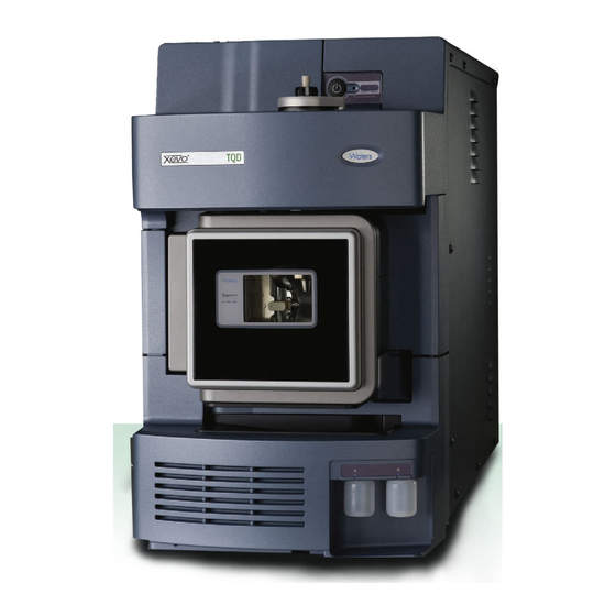
For mass spectrometer specifications, see the Xevo TQD Site Preparation Guide (part number 715003099). Figure 1–1: Xevo TQD IVD shown with visor down and with visor up 1.1.1 IntelliStart technology IntelliStart™ technology monitors LC/MS/MS performance and reports when the instrument is ready for use. -
Page 20: Software And Data System
Console functions independently of MassLynx software. As such, it does not recognize or control MassLynx data systems. Consult the Instrument Console system’s online Help for details. 1. In Waters product documentation, the term “fluidics” denotes plumbing connections and components and the fluid pathways within and among instruments or devices. It also appears in the product name “IntelliStart fluidics”... -
Page 21: Electrospray Ionization (Esi)
Electrospray ionization (ESI) In electrospray ionization (ESI), a strong electrical charge is applied to the eluent as it emerges from a nebulizer. The droplets that compose the resultant aerosol undergo a reduction in size (solvent evaporation). As solvent continues to evaporate, the charge density increases until the droplet surfaces eject ions (ion evaporation). -
Page 22: System Operation
Figure 1–2: IntelliStart fluidics system: Selector valve LC Column Waste Pump Rinse Source Reservoir A Reservoir B 1.3.2 System operation The software automatically controls solvent and sample delivery during auto-tuning, auto-calibration, and method development. The selector valve systematically makes connections between the components of the IntelliStart fluidics system to carry out operations processed by the software. - Page 23 The mass-separated ions pass into the T-Wave™ collision cell where they either undergo collision-induced dissociation (CID) or pass to the second quadrupole. Any fragment ions are then mass-analyzed by the second quadrupole. The transmitted ions are detected by the photomultiplier detection system. The signal is amplified, digitized, and sent to the MassLynx mass spectrometry software.
-
Page 24: Ms Operating Modes
MS operating modes The following table shows the MS operating modes. Table 1–1: MS operating modes Operating mode Collision cell Pass all masses Resolving (scanning) Pass all masses Resolving (static) In MS mode, used for instrument tuning and calibration before an MS/MS analysis, the instrument can acquire data at scan speeds as high as 10,000 Da/s. -
Page 25: Ms/Ms Operating Modes
MS/MS operating modes The following table shows the MS/MS operating modes, described in more detail in the following pages. Table 1–2: MS/MS operating modes Operating mode Collision cell Product (daughter) ion Static (at precursor Fragment precursor Scanning spectrum mass) ions and pass all masses Precursor (parent) ion Scanning... -
Page 26: Product Ion Mode
1.6.1 Product ion mode Product, or daughter, ion mode is the most commonly used MS/MS operating mode. You can specify an ion of interest for fragmentation in the collision cell, thus yielding structural information. Figure 1–4: Product ion mode Collision cell Static (at precursor mass) Fragmenting precursor Scanning... -
Page 27: Precursor Ion Mode
1.6.5 RADAR In RADAR mode, the Xevo TQD IVD rapidly alternates between MRM and full-scan MS acquisition modes. The instrument tracks target analytes with precision in MRM mode. At the same time, it September 7, 2016, 715003560IVD Rev. C... -
Page 28: Constant Neutral-Loss Mode
scans (in MS mode) the background for all other components. RADAR mode enables fast characterization of potential matrix effects, providing a platform for more robust method development. 1.6.5.1 Typical application You typically use RADAR mode during method development before performing MRM or PICS analyses to quantify known analytes in complex samples: •... -
Page 29: Sample Inlet
Leak sensors Leak sensors in the Xevo TQD IVD, and in the drip trays of the ACQUITY UPLC IVD system and the ACQUITY UPLC I-Class IVD system, continuously monitor system components for leaks. A leak sensor stops system flow when its optical sensor detects about 1.5 mL of accumulated,... -
Page 30: Rear Panel Connections
1.10 Rear panel connections The figure shows the rear-panel locations of connectors used to operate the instrument via external devices. Figure 1–8: Instrument rear panel Event inputs and outputs Shielded Ethernet Roughing pump control Power Source vacuum Turbo vacuum Collision cell gas inlet (Argon) Source vent... -
Page 31: Preparing For Operation
To avoid causing severe damage to the instrument, use compatible solvents only. There are fewer compatible solvents for the Xevo TQD IVD than for the LC systems. Therefore, use only those solvents listed as compatible for the MS. For more details, refer to the following sources: •... -
Page 32: Verifying The Mass Spectrometer's State Of Readiness
Allow 3 minutes for the embedded PC (located inside the mass spectrometer) to initialize and to sound an alert indicating that the PC is ready. Tip: The Power and Status LEDs change as follows: • The Power LED of each system instrument and device shows green. •... -
Page 33: Tuning And Calibration Information
The ACQUITY UPLC IVD and ACQUITY UPLC I-Class IVD systems run at high flow rates. To optimize desolvation, and thus sensitivity, run the ACQUITY Xevo TQD IVD system at appropriate gas-flows and desolvation temperatures. When you specify a flow rate, IntelliStart software specifies these parameter settings. -
Page 34: Purging The Infusion Pump
To install the reservoir bottles: Remove the reservoir bottle caps. Screw the reservoir bottles onto the instrument, as shown below. TP03410 For each reservoir bottle, ensure that the end of the solvent delivery tube is positioned so that it is close to, but does not touch, the bottom of the bottle. To install low-volume vials: If a standard reservoir bottle is fitted, remove it. -
Page 35: Leaving The Mass Spectrometer Ready For Operation
To reboot the instrument’s software: Ensure that MassLynx software is closed. Insert a short length (about 7.5 cm) of PEEK™ tubing, or a similar object, into the reset button aperture at the top, right-hand side of the instrument’s front panel. Reset button aperture TP03415 Remove the PEEK tubing from the reset button aperture. - Page 36 September 7, 2016, 715003560IVD Rev. C Page 36...
-
Page 37: Installing And Removing The Esi Probe
Installing and removing the ESI probe Preparing the mass spectrometer for ESI (electrospray ionization) requires installing the ESI probe. For further details on running ESI applications, see page Installing the ESI probe 3.1.1 Required material Chemical-resistant, powder-free gloves Warning: To avoid personal contamination with biohazards or toxic materials, and to avoid spreading contamination to uncontaminated surfaces, wear clean, chemical-resistant, powder-free gloves while performing this procedure. - Page 38 With the probe label facing you, carefully slide the ESI probe into the hole in the probe adjuster assembly, ensuring that the probe location dowel aligns with the location hole of the probe adjuster assembly. Probe label Probe locking ring Probe location dowel Location hole of the probe adjuster assembly...
-
Page 39: Removing The Esi Probe
Requirements: • If you are replacing the tubing between the selector valve and the probe, minimize the new tubing’s, length to reduce peak broadening. • When cutting the tubing to length, cut it squarely (that is, perpendicular to its horizontal axis). - Page 40 September 7, 2016, 715003560IVD Rev. C Page 40...
-
Page 41: Maintenance Procedures
Replace the turbomolecular pump oil. Every 4 years. page Replace the turbo pump bearings and Every 4 years. Contact Waters. oil. September 7, 2016, 715003560IVD Rev. C Page 41... -
Page 42: Spare Parts
Replace only spare parts, which are the parts mentioned in this document. For details about spare ® parts, use the Waters Quality Parts Locator on the Waters Web site’s Services & Support page. September 7, 2016, 715003560IVD Rev. C Page 42... -
Page 43: Troubleshooting With Connections Insight
“intelligent” device management (IDM) Web service that enables Waters to provide proactive service and support for the ACQUITY UPLC IVD and ACQUITY UPLC I-Class IVD systems. To use Connections INSIGHT, you must install its service agent software on your MassLynx workstation. -
Page 44: Safety And Handling
In the Instrument Console, click Stop Flow to stop the LC flow; if column flow is required, divert the LC flow to waste as follows: In the Instrument Console system tree, expand Xevo TQD IVD, Interactive Fluidics. Click Control Select Waste, as the flow state. -
Page 45: Removing And Refitting The Source Enclosure
In the Instrument Console, click Standby , and confirm that the Operate indicator is not illuminated. Wait 3 minutes to allow the desolvation gas flow to cool the probe and source. In the Instrument Console, click API , to stop the desolvation gas flow. Lift the visor on the front of the instrument so that it is clear of all the source components and probe. -
Page 46: Fitting The Source Enclosure To The Instrument
Using both hands, grasp the source enclosure and lift it vertically off the two supporting studs on the source adaptor housing. Cable storage positions Supporting stud TP03164 Source enclosure Store the cables neatly by plugging them into the cable-storage positions on the rear of the source enclosure. -
Page 47: Operating The Source Isolation Valve
Operating the source isolation valve You must close the source isolation valve to isolate the source from the instrument vacuum system for certain maintenance procedures. 4.7.1 Required material Chemical-resistant, powder-free gloves Warning: To avoid personal contamination with biohazards or toxic materials, and to avoid spreading contamination to uncontaminated surfaces, wear clean, chemical-resistant, powder-free gloves when working with the source components. - Page 48 Close the source isolation valve by moving its handle counterclockwise, to the vertical position. Isolation valve handle in closed position Warning: To avoid puncture wounds, take great care while working with the source enclosure open; the ESI probe tip is sharp. To open the source isolation valve after completing a maintenance procedure: Open the source isolation valve by moving its handle clockwise to the horizontal position.
-
Page 49: Removing O-Rings And Seals
Removing O-rings and seals When performing certain maintenance procedures, you must remove O-rings or seals from instrument components. An O-ring removal kit can be purchased separately. Figure 4–1: O-ring removal kit Tool 1 Tool 2 Notice: To avoid scratching the O-ring or seal, take care while using the removal tools to remove it from components. -
Page 50: Emptying The Exhaust Trap Bottle
4.10 Emptying the exhaust trap bottle Inspect the exhaust trap bottle in the instrument’s exhaust line daily, and empty it before it is more than 10% full. Figure 4–2: Nitrogen exhaust trap bottle: To laboratory exhaust (12-mm) From instrument waste (12-mm) Valve control cable (from instrument) 4.10.1... -
Page 51: Gas Ballasting The Roughing Pump
Warning: To avoid spreading contamination, dispose of the waste liquid in accordance with local environmental regulations. Dispose of the waste liquid in accordance with local environmental regulations. Fit and fully tighten the nitrogen exhaust trap bottle to the cap. Secure the nitrogen exhaust trap bottle in the upright position. Close the source enclosure. -
Page 52: Gas Ballasting A Pump Fitted With A Screwdriver-Operated Gas Ballast Valve
Notice: To avoid shortening the oil life and pump life, routinely gas ballast the roughing pump according to the guidelines below. Gas ballast the roughing pump when these conditions apply: • With ESI operation, once a week. • When the roughing pump oil appears cloudy. •... -
Page 53: Gas Ballasting A Pump Fitted With A Handle-Operated Gas Ballast Valve
Run the pump for 30 to 60 minutes. Tip: It is normal for the roughing pump temperature to increase during ballasting. To maintain an ambient temperature of less than 40 °C in the space where the pump is located, ensure the space is adequately ventilated. Use the flat-blade screwdriver to turn the gas ballast valve to the closed position 4.11.2 Gas ballasting a pump fitted with a handle-operated gas ballast... -
Page 54: Checking The Roughing Pump Oil Level
4.12 Checking the roughing pump oil level To ensure correct operation of the roughing pump, do not operate it with the oil level at less than 30% of the maximum level, as indicated in the pump’s sight glass. See also: The Sogevac SV40 BI Pump Manual. -
Page 55: Replacing The Roughing Pump's Oil
Use the 8-mm Allen wrench to unscrew and remove the roughing pump’s oil filler plug (see the figure on page 51). Requirement: To maintain pump performance, use only Anderol vacuum oil, type LVO200. Using the funnel, add Anderol vacuum oil, type LVO200, into the oil filler aperture until the oil reaches the oil level sight glass MAX level. - Page 56 • 1-L container of Anderol vacuum oil, type LVO200 To replace the roughing pump oil: Gas ballast the roughing pump for 1 hour, to reduce the oil’s viscosity (see page 51). Rationale: Gas ballasting helps to circulate and mix the oil through the pump before draining.
-
Page 57: Replacing The Roughing Pump's Oil Demister Element
Ensure that the O-ring on the oil drain plug is clean and properly seated. Notice: To avoid oil leakage when fitting the oil drain plug to the roughing pump, observe these precautions: • Ensure that the plug is not cross-threaded. •... - Page 58 • 6-mm Allen wrench • 10-mm wrench To remove the roughing pump oil demister element: Vent and shut down the instrument (see the mass spectrometer’s online Help for details). Allow the roughing pump to cool. Warning: To avoid personal contamination with biohazards or toxic materials, and to avoid spreading contamination to uncontaminated surfaces, wear clean, chemical-resistant, powder-free gloves when adding or replacing oil.
- Page 59 Use the 10-mm wrench to remove the nut that secures the oil demister element to the exhaust flange. Spring Securing nut TP02686 Holding the oil demister element slightly elevated to prevent the loss of the spring, remove the exhaust flange from the oil demister element. TP02692 Remove the spring from the oil demister element.
- Page 60 Dispose of the oil demister element in accordance with local environmental regulations. Warning: To avoid personal contamination with biohazards or toxic materials, and to avoid spreading contamination to uncontaminated surfaces, wear clean, chemical-resistant, powder-free gloves when replacing the oil demister element. The pump oil can be irritant, or contaminated with biohazardous or toxic analyte accumulated during normal operation.
-
Page 61: Replacing The Turbomolecular Pump's Oil Reservoir
4.16 Replacing the turbomolecular pump’s oil reservoir The turbomolecular pump’s oil reservoir regulates the supply of oil to the pump bearings. Replace the oil reservoir every four years. The service interval for the turbomolecular pump’s bearings, which users cannot service, is also four years. 4.16.1 Required materials •... - Page 62 Use the 3 mm screwdriver to remove the 7 screws securing the lower front cover to the instrument, and slide the cover off the instrument to reveal the fan panel. Screws Use the 4 mm screwdriver to remove the screw securing the fan panel to the instrument chassis.
-
Page 63: Cleaning The Source Components
Result: The turbomolecular pump cover plate is now accessible. Turbomolecular pump cover plate If the fan panel is obstructing access to the turbomolecular pump cover plate, disconnect the fans power cable from the fan panel. ® 10. Follow the instructions in the Pfeiffer manual (Pfeiffer TurboDrag Pump, HiPace 300) to remove the turbomolecular pump cover plate, replace the oil reservoir and porex rods, and reattach the cover plate. -
Page 64: Cleaning The Sampling Cone Assembly
If cleaning the ion block and isolation valve fails to increase signal sensitivity, also clean the ion guide assembly. See page If all these steps fail to increase signal sensitivity, contact Waters Technical Service. 4.18 Cleaning the sampling cone assembly You can remove the sampling cone assembly (the sample cone, O-ring, and cone gas nozzle) for cleaning without venting the instrument. -
Page 65: Disassembling The Sampling Cone Assembly
Grasp the cone gas nozzle handle, and use it to rotate the sampling cone assembly 90 degrees, moving the handle from the vertical to the horizontal position. Sampling cone assembly Cone gas nozzle handle TP03131 Notice: To avoid damaging the instrument by sudden venting, do not open the isolation valve at any time while the sampling cone assembly is removed from the ion block assembly. - Page 66 • Combined 2.5-mm Allen wrench and cone extraction tool Warning: To avoid personal contamination with biohazards or toxic materials, and to avoid spreading contamination to uncontaminated surfaces, wear clean, chemical-resistant, powder-free gloves when working with the sampling cone assembly. To disassemble the sampling cone assembly: Slide the collar to the end of the combined 2.5-mm Allen wrench and cone extraction tool.
- Page 67 Rotate the tool and collar counter-clockwise and then lift them to remove the sample cone from the cone gas nozzle. Remove the O-ring from the sample cone. Cone gas nozzle Cone gas nozzle handle O-ring Warning: To avoid personal contamination with biologically hazardous, or toxic materials, and to avoid spreading contamination, dispose of the O-ring or seal in accordance with local environmental regulations.
-
Page 68: Cleaning The Sample Cone And Cone Gas Nozzle
4.18.3 Cleaning the sample cone and cone gas nozzle 4.18.3.1 Required materials • Chemical-resistant, powder-free gloves. • Appropriately sized glass vessels in which to completely immerse components when cleaning. Use only glassware not previously cleaned with surfactants. • HPLC-grade (or better) methanol. •... -
Page 69: Assembling The Sampling Cone Assembly
Carefully remove the components from the vessels, and blow-dry them with inert, oil-free gas. Inspect each component for persisting contamination. If contamination is present, do as follows: Use the wash bottle containing 1:1 methanol/water to rinse the component over the large beaker. -
Page 70: Fitting The Sampling Cone Assembly To The Source
4.18.5 Fitting the sampling cone assembly to the source 4.18.5.1 Required material Chemical-resistant, powder-free gloves Warning: To avoid personal contamination with biohazards or toxic materials, and to avoid spreading contamination to uncontaminated surfaces, wear clean, chemical-resistant, powder-free gloves when working with the source components. Warning: To avoid puncture wounds, take great care while working with the source enclosure open;... -
Page 71: Cleaning The Extraction Cone
4.19 Cleaning the extraction cone Clean the ion block and extraction cone when cleaning the sample cone and cone gas nozzle fails to increase signal sensitivity. You must remove the ion block assembly from the source assembly to clean the extraction cone. 4.19.1 Removing the ion block assembly from the source assembly 4.19.1.1... -
Page 72: Removing The Extraction Cone From The Ion Block
Use the combined 2.5-mm Allen wrench and cone extraction tool to unscrew the 4 captive screws that secure the ion block assembly. Screws securing the Ion block TP03130 Remove the ion block assembly from the PEEK ion block support. PEEK ion block support Ion block assembly TP03130... - Page 73 • Combined 2.5-mm Allen wrench and cone extraction tool Warning: To avoid personal contamination with biohazards or toxic materials, and to avoid spreading contamination to uncontaminated surfaces, wear clean, chemical-resistant, powder-free gloves when working with the ion block components. To remove the extraction cone from the ion block: On the rear of the ion block, use the combined 2.5-mm Allen wrench and cone extraction tool to loosen the captive screws securing the 2 PEEK extraction cone retainer clips, and then rotate the retainer clips clear of the extraction cone.
-
Page 74: Cleaning The Extraction Cone
Remove the extraction cone from the ion block. Extraction cone aperture Remove the extraction cone handle insulator from the extraction cone handle. 4.19.3 Cleaning the extraction cone 4.19.3.1 Required materials • Chemical-resistant, powder-free gloves. • Appropriately sized glass vessel in which to completely immerse the extraction cone when cleaning. -
Page 75: Fitting The Extraction Cone To The Ion Block
To clean the extraction cone: Immerse the extraction cone in the glass vessel containing 1:1 methanol/water. Tip: If the extraction cone is obviously contaminated, use 45:45:10 methanol/water/formic acid. Place the vessel in the ultrasonic bath for 30 minutes. If you used formic acid in the cleaning solution, do as follows: Rinse the extraction cone by immersing it in a glass vessel containing water and then placing the vessel in the ultrasonic bath for 20 minutes. -
Page 76: Fitting The Ion Block Assembly To The Source Assembly
Fit the extraction cone onto the ion block. Rotate the 2 PEEK extraction cone retainer clips to secure the extraction cone, then use the combined 2.5-mm Allen wrench and cone extraction tool to tighten the retainer clip securing screws. 4.19.5 Fitting the ion block assembly to the source assembly 4.19.5.1 Required materials... - Page 77 To avoid personal contamination with biohazards or toxic materials, and to avoid spreading contamination to uncontaminated surfaces, wear clean, chemical-resistant, powder-free gloves when working with the ion block assembly. To disassemble the ion block assembly: Remove the ion block assembly from the source assembly (see page 71).
- Page 78 Use the combined 2.5-mm Allen wrench and cone extraction tool to loosen the 2 ion block cover plate captive securing screws. Ion block cover plate securing screw Ion block cover plate Remove the ion block cover plate. Grasp the isolation valve and pull it out of the ion block. Isolation valve O-ring Use the O-ring removal kit to carefully remove the isolation valve O-ring (see...
- Page 79 If the isolation valve O-ring shows signs of deterioration or damage, dispose of it in accordance with local environmental regulations. 10. Use the combined 2.5-mm Allen wrench and cone extraction tool to loosen the captive PEEK terminal block securing screw. PEEK terminal block securing screw...
- Page 80 13. Use the O-ring removal kit to carefully remove the cover seal from the ion block (see also page 49). Cover seal Cone gas O-ring 14. Use the O-ring removal kit to carefully remove the cone gas O-ring from the ion block. Warning: To avoid spreading contamination, dispose of the cover seal and cone gas O-ring in accordance with local environmental regulations.
- Page 81 16. Insert the combined 2.5-mm Allen wrench and cone extraction tool through the hole in the ion block blanking plug, and then unscrew and remove the ion block blanking plug and associated seal. Blanking plug Combined 2.5-mm Allen wrench and cone extraction tool Warning: To avoid personal contamination with biologically hazardous, or toxic materials, and to avoid spreading contamination, dispose of the blanking plug seal in accordance with...
- Page 82 18. Use the combined 2.5-mm Allen wrench and cone extraction tool to remove the captive screws securing the 2 PEEK extraction cone retainer clips. Securing screw Retainer clip Extraction cone Notice: • To avoid damaging the extraction cone aperture, take great care when removing the extraction cone from the ion block.
-
Page 83: Cleaning The Ion Block Components
21. Remove the extraction cone seal from the ion block. Extraction cone seal 4.20.2 Cleaning the ion block components 4.20.2.1 Required materials • Chemical-resistant, powder-free gloves. • Appropriately sized glass vessels in which to completely immerse components when cleaning. Use only glassware not previously cleaned with surfactants. •... -
Page 84: Assembling The Source Ion Block Assembly
Tip: If the components are obviously contaminated, use 45:45:10 methanol/water/formic acid. Place the vessels in the ultrasonic bath for 30 minutes. If you used formic acid in the cleaning solution, do as follows: Rinse the components by immersing them separately in glass vessels containing water and then place the vessels in the ultrasonic bath for 20 minutes. - Page 85 To assemble the ion block assembly: Fit the extraction cone seal onto the ion block. Notice: To avoid damaging the extraction cone aperture, take great care when fitting the extraction cone to the ion block. Fit the extraction cone handle’s insulator onto the extraction cone handle. Fit the extraction cone onto the ion block.
-
Page 86: Cleaning The Ion Guide Assembly
20. Grasp the sampling cone assembly handle, and use it to rotate the sampling cone assembly through 90 degrees. 21. Fit the ion block assembly onto the source assembly (see page 76). 4.21 Cleaning the ion guide assembly Clean the ion guide assembly if cleaning the ion block and isolation valve fails to increase signal sensitivity. - Page 87 Use the 3-mm Allen wrench to unscrew and remove the 4 screws securing the PEEK ion block support to the adaptor housing, and remove the ion block support. Ion guide assembly Securing screws PEEK ion block Adaptor housing support Warning: To avoid spreading contamination, dispose of the O-rings in accordance with local environmental regulations.
-
Page 88: Cleaning The Ion Guide Assembly
Notice: To avoid damaging the ion guide assembly when removing it from the source assembly, do not grasp the ion guide by its metal lens plates. Instead, grasp the circuit boards on the top and bottom of the device. Carefully grasp the circuit boards on the top and bottom of the ion guide, and remove the guide from the adaptor housing. - Page 89 Notice: To avoid damaging the ion guide assembly, use only methanol and water as solvents. Do not use acetone, chlorinated solvents, or acid. To clean the ion guide assembly: Bend a PEEK or PTFE tube into a hook shape. Insert one end of the hook into one of the holes in the ion guide’s rear circuit board carrier. Notice: To avoid vibration-caused damage to the ion guide assembly, ensure that the bottom of the assembly is not in contact with the bottom of the glass vessel.
-
Page 90: Removing The Differential Aperture From The Ion Guide
4.21.3 Removing the differential aperture from the ion guide Notice: To avoid a reduction in sensitivity, remove and clean the differential aperture only when cleaning the ion guide assembly fails to remove all visible contamination from the differential aperture. Sensitivity can diminish if the differential aperture fails to correctly align with the ion guide during refitting. -
Page 91: Fitting The Differential Aperture To The Ion Guide Assembly
To clean the differential aperture: Warning: To avoid personal contamination with biohazards or toxic materials, and to avoid spreading contamination to uncontaminated surfaces, wear clean, chemical-resistant, powder-free gloves when handling the differential pumping aperture, and throughout this procedure. Use the glass-fiber pen to remove gross contamination from the differential aperture by gentle abrasion. -
Page 92: Fitting The Ion Guide Assembly To The Source Assembly
4.21.5 Fitting the ion guide assembly to the source assembly 4.21.5.1 Required material Clean, chemical-resistant, powder-free gloves Warning: Warning: To avoid personal contamination with biohazards or toxic materials, and to avoid spreading contamination to uncontaminated surfaces, wear clean, chemical-resistant, powder-free gloves when working with the source components. Notice: To avoid damaging the ion guide assembly when fitting it to the source assembly, avoid pushing on the metal ion guide lens plates. -
Page 93: Replacing The Esi Probe Tip And Gasket
Fit the source enclosure onto the instrument (see page 46). 4.22 Replacing the ESI probe tip and gasket Replace the ESI probe tip if a blockage occurs in the internal metal sheathing through which the stainless steel capillary passes or if the probe tip is damaged. 4.22.1 Removing the ESI probe tip and gasket 4.22.1.1... - Page 94 Unscrew and remove the ESI probe tip by holding the probe shaft steady, using the 7-mm wrench, and unscrewing the probe tip using the 10-mm wrench, as shown in the following figure: 10-mm wrench Probe tip 7-mm wrench 10-mm wrench Probe tip September 7, 2016, 715003560IVD Rev.
-
Page 95: Fitting The Esi Probe Tip And Gasket
Remove the metal gasket from the probe tip. Metal gasket Warning: To avoid spreading contamination, dispose of the probe tip and metal gasket in accordance with local environmental regulations. They can be contaminated with biohazards or toxic materials. Dispose of the metal gasket in accordance with local environmental regulations. If the probe tip is damaged, dispose of it in accordance with local environmental regulations. -
Page 96: Replacing The Esi Probe Sample Capillary
Use the nebulizer adjuster knob to adjust the capillary so that it protrudes by approximately 0.5 mm from the end of the probe. Fit the ESI probe onto the source (see page 37). 4.23 Replacing the ESI probe sample capillary Replace the stainless steel sample capillary in the ESI probe if it becomes blocked and cannot be cleared, or if it becomes contaminated or damaged. - Page 97 Use the combined 2.5-mm Allen wrench and cone extraction tool to remove the 3 screws retaining probe end-cover. End-cover retaining screws Remove the end cover and gasket from the probe assembly. Nebulizer adjuster knob Gasket End cover Unscrew and remove the nebulizer adjuster knob. September 7, 2016, 715003560IVD Rev.
- Page 98 Use the 10-mm wrench to remove the probe tip. 10-mm wrench Probe tip Tip: If the probe tip is difficult to remove, use the 7-mm wrench in conjunction with the 10-mm wrench. 7-mm wrench 10-mm wrench Probe tip Remove the metal gasket from the probe tip. Metal gasket September 7, 2016, 715003560IVD Rev.
-
Page 99: Installing The New Capillary
Remove the PEEK union/UNF coupling assembly and capillary from the probe. PEEK union/UNF coupling assembly Capillary Unscrew and remove the knurled collar from the UNF coupling. PEEK union UNF coupling Locknut Knurled collar Conductive sleeve 10. Remove the knurled collar and conductive sleeve from the capillary. 11. - Page 100 • 10-mm wrench • Needle-nose pliers • LC pump • HPLC-grade (or better) 1:1 acetonitrile/water • Ferrule • Seal • PTFE liner tubing • Conductive sleeve • Red PEEK tubing • Sharp knife or PEEK tubing cutter • Metal gasket for the probe tip •...
- Page 101 Fit the UNF coupling onto the new capillary. Use the needle-nose pliers to slide a new liner sleeve and ferrule onto the capillary. Insert the capillary in the PEEK union, and ensure that it is fully seated. Screw the UNF coupling into the PEEK union, finger-tight only. Gently tug on the capillary, testing to ensure that it stays in place.
-
Page 102: Replacing The Ion Block Source Heater
19. Use the combined 2.5-mm Allen wrench and cone extraction tool to fit and tighten the 3 screws retaining the probe end-cover. 20. Return the combined 2.5-mm Allen wrench and cone extraction tool to its storage location on the source adaptor housing. 21. - Page 103 Ensure that the isolation valve is closed. Isolation valve handle in closed position Use the combined 2.5-mm Allen wrench and cone extraction tool to loosen the 2 captive screws securing the ion block cover plate. Ion block cover plate securing screw Ion block cover plate Remove the ion block cover plate.
- Page 104 Use the combined 2.5-mm Allen wrench and cone extraction tool to remove the 2 screws securing the heater wires to the PEEK terminal block. Heater cartridge wire securing screws PEEK terminal block Use the needle-nose pliers to carefully swing the ring terminal tags out of the terminal block. Ring terminal tag September 7, 2016, 715003560IVD Rev.
-
Page 105: Replacing The Source Assembly Seals
Use the needle-nose pliers to gently grasp the heat-shrink tubing on the heater cartridge assembly and slide the assembly out of the ion block. Heat-shrink tubing Heater cartridge assembly Dispose of the heater cartridge assembly. Notice: To avoid damaging the heater cartridge assembly wires, do not bend or twist them when fitting the assembly to the ion block. -
Page 106: Removing The Probe Adjuster Assembly Probe Seal And Source Enclosure Seals
• Probe adjuster assembly nebulization gas seal • Source enclosure seal • Nebulizer gas seal • Desolvation gas seal 4.25.1 Removing the probe adjuster assembly probe seal and source enclosure seals 4.25.1.1 Required materials • Chemical-resistant, powder-free gloves • O-ring removal kit Warning: To avoid personal contamination with biohazards or toxic materials, and to avoid spreading contamination to uncontaminated surfaces, wear clean, chemical-resistant,... -
Page 107: Fitting The New Source Enclosure And Probe Adjuster Assembly Seals
Use the O-ring removal kit to carefully remove the following seals from the source enclosure: • Source enclosure seal • Nebulizer gas seal • Desolvation gas seal Nebulizer gas seal Desolvation gas seal Source enclosure seal TP03164 Warning: To avoid spreading contamination, dispose of the seals in accordance with local environmental regulations. -
Page 108: Replacing The Air Filter
To fit the new source enclosure and probe adjuster assembly probe seals: Ensure that all the grooves for seals are free of dirt and debris. Tip: If contamination is present, use 1:1 methanol/water applied to a lint-free cloth to carefully clean the grooves. Requirement: Ensure that the tails of the source enclosure seals are correctly located in the groove when fitting them to the source enclosure. - Page 109 Disconnect the probe cable from the high-voltage connector, and leave the cable in a position that does not obstruct the air filter grill. Air filter grill Probe cable TP03403 Open the air filter grill by pulling the tab at the top of the grill toward you. Air filter grill tab Air filter grill TP03405...
-
Page 110: Replacing The Instrument's Fuses
Close the air filter grill. Connect the probe cable to the high-voltage connector. Close the source enclosure. 10. Lower the instrument’s visor. 4.27 Replacing the instrument’s fuses Warning: To avoid electrical shock, disconnect the mass spectrometer from the power supply before replacing fuses. The mass spectrometer has two fuses, and uses double pole/neutral fusing circuitry. -
Page 111: A Safety Advisories
Heed all warnings when you install, repair, or operate any Waters instrument or device. Waters accepts no liability in cases of injury or property damage resulting from the failure of individuals to comply with any safety precaution when installing, repairing, or operating any of its instruments or devices. -
Page 112: Specific Warnings
A.1.1.1 Burst warning This warning applies to Waters instruments and devices fitted with nonmetallic tubing. Warning: To avoid injury from bursting, nonmetallic tubing, heed these precautions when working in the vicinity of such tubing when it is pressurized: •... - Page 113 LC solvent should the nitrogen supply fail. A.1.1.4 Biohazard warning The following warning applies to Waters instruments and devices that can process material containing biohazards, which are substances that contain biological agents capable of producing harmful effects in humans.
-
Page 114: Notices
A.1.1.5 Biohazard and chemical hazard warning These warnings apply to Waters instruments and devices that can process biohazards, corrosive materials, or toxic materials. Warning: To avoid personal contamination with biohazards, toxic materials, or corrosive materials, you must understand the hazards associated with their handling. -
Page 115: Warnings That Apply To All Waters Instruments And Devices
Requirement: Wear clean, chemical-resistant, powder-free gloves when handling samples. Warnings that apply to all Waters instruments and devices When operating this device, follow standard quality-control procedures and the equipment guidelines in this section. Attention: Changes or modifications to this unit not expressly approved by the party responsible for compliance could void the user’s authority to operate the equipment. - Page 116 Attention: Manipulez les tubes en polymère sous pression avec precaution: • Portez systématiquement des lunettes de protection lorsque vous vous trouvez à proximité de tubes en polymère pressurisés. • Eteignez toute flamme se trouvant à proximité de l’instrument. • Evitez d'utiliser des tubes sévèrement déformés ou endommagés. •...
- Page 117 警告:当有压力的情况下使用管线时,小心注意以下几点: • 当接近有压力的聚合物管线时一定要戴防护眼镜。 • 熄灭附近所有的火焰。 • 不要使用已经被压瘪或严重弯曲的管线。 • 不要在非金属管线中使用四氢呋喃或浓硝酸或浓硫酸。 要了解使用二氯甲烷及二甲基亚枫会导致非金属管线膨胀,大大降低管线的耐压能力。 경고: 가압 폴리머 튜브로 작업할 경우에는 주의하십시오. • 가압 폴리머 튜브 근처에서는 항상 보호 안경을 착용하십시오. • 근처의 화기를 모두 끄십시오. • 심하게 변형되거나 꼬인 튜브는 사용하지 마십시오. • 비금속(Nonmetallic) 튜브를 테트라히드로푸란(Tetrahydrofuran: THF) 또는 농축...
-
Page 118: Warnings That Address The Replacing Of Fuses
警告: ユ ー ザ ー は、 製造元 に よ り 指定 さ れ て い な い方法で機器 を 使用す る と 、 機器が提供 し て い る 保証が無効 に な る 可能性が あ る こ と に 注意 し て 下 さ い。 Warnings that address the replacing of fuses The following warnings pertain to instruments and devices equipped with user-replaceable fuses. -
Page 119: Electrical And Handling Symbols
Attention: pour éviter tout risque d'incendie, remplacez toujours les fusibles par d'autres du type et de la puissance indiqués dans la rubrique "Remplacement des fusibles" du chapitre traitant des procédures de maintenance. Vorsicht: Zum Schutz gegen Feuer die Sicherungen nur mit Sicherungen ersetzen, deren Typ und Nennwert im Abschnitt "Sicherungen ersetzen"... - Page 120 Table A–1: Electrical symbols (Continued) Symbol Description Alternating current (3 phase) Safety ground Frame, or chassis, terminal Fuse Functional ground Input Output September 7, 2016, 715003560IVD Rev. C Page 120...
-
Page 121: Handling Symbols
A.7.2 Handling symbols The following handling symbols and their associated statements can appear on labels affixed to the packaging in which instruments, devices, and component parts are shipped. Table A–2: Handling symbols Symbol Description Keep upright! Keep dry! Fragile! Use no hooks! Upper limit of temperature Lower limit of temperature Temperature limitation... - Page 122 September 7, 2016, 715003560IVD Rev. C Page 122...
-
Page 123: B External Connections
To avoid damaging the mass spectrometer, observe the following precautions: • Contact Waters Technical Service before moving it. • If you must transport the instrument, or remove it from service, contact Waters Technical Service for recommended cleaning, flushing, and packaging procedures. See page External wiring and vacuum connections Rear panel connections appear in the figure below. -
Page 124: Connecting The Oil-Filled Roughing Pump
PVC exhaust tubing (included in the Waters Rough Pump Connect Kit) • PVC hose clamps (included in the Waters Rough Pump Connect Kit) • 1-inch ID vacuum hose (included in the Waters Rough Pump Connect Kit) September 7, 2016, 715003560IVD Rev. C Page 124... - Page 125 Requirements: Consider the following requirements when connecting the roughing pump: • The pump must be horizontal, or within one degree of horizontal. • The ambient temperature of the area in which you place the pump must range between 15 and 40 ºC. •...
- Page 126 Attach the NW25 tee to the inlet of the pump using the NW25 center ring, and then secure the connection with a clamp. 1-inch ID vacuum hose Clamps 10-mm nylon tube Flange NW25 tee 10-mm reducer fitting Pump inlet TP03414 Using the NW25 center rings and clamp, and the 7-mm nut driver, attach the flanged end of a length of 1-inch ID vacuum hose to the top port on the NW25 tee, and the 10-mm reducer fitting and a length of 10-mm ID nylon tubing to the middle (perpendicular) port on the tee.
-
Page 127: Connecting Electric Cables To The Oil-Filled Roughing Pump
B.2.1 Connecting electric cables to the oil-filled roughing pump Figure B–2: Roughing pump electrical connections Detector rear panel Roughing pump d.c. connector Roughing pump main power connector To power source To connect cables: Connect the relay cable from the roughing pump’s d.c. connector to the pump connector on the instrument’s rear panel. -
Page 128: Connecting The Edwards Oil-Free Roughing Pump
10-mm reducer fitting (included in the installation kit) • 10-mm ID nylon tube (included in installation kit) • 12.7-mm clear PVC exhaust tubing (included in the Waters Rotary Pump Kit) • PVC hose clamps (included in the Waters Rotary Pump Kit) •... - Page 129 Requirements: Consider the following requirements when connecting the roughing pump: • The pump must be horizontal, or within one degree of horizontal. • The ambient temperature of area in which you place the pump must range between 15 and 40 ºC. For proper ventilation, the following minimum clearances must apply: Back-side minimum clearance is Right-side minimum clearance is...
-
Page 130: Connecting Electric Cables To The Edwards Oil-Free Roughing Pump
Connect the opposite end of the 10-mm nylon tube to the 10-mm source vent port on the instrument’s rear panel. Notice: To prevent serious damage to the instrument, two separate exhaust systems are required: one for nitrogen, the other for the roughing pump. Vent the exhausts to atmosphere through separate lines. -
Page 131: Connecting To The Nitrogen Gas Supply
Wrench • Nitrogen supply in-line filter • 6-mm PTFE tubing (included in the Waters Rough Pump Connect Kit) • Nitrogen regulator To connect the nitrogen gas supply: Use the sharp knife to cut a 3.8-cm to 5.0-cm length of 6-mm PTFE tubing. -
Page 132: Connecting To The Collision Cell Gas Supply
B.6.1 Required materials • Chemical-resistant, powder-free gloves • Sharp knife • 10-mm and 12-mm PTFE tubing (included in the Waters Rough Pump Connect Kit) ® • Snoop (or equivalent) leak detector liquid September 7, 2016, 715003560IVD Rev. C Page 132... - Page 133 To connect the nitrogen exhaust line: Warning: To avoid exposure to biohazards or toxic LC solvents carried in the nitrogen exhaust, ensure that the nitrogen exhaust is vented via the nitrogen exhaust trap bottle and laboratory exhaust system. The laboratory exhaust system must provide a minimum vacuum of 0.20 kPa (2 mbar, 0.03 psi) below atmospheric pressure (negative pressure).
- Page 134 Warning: To prevent leaks in the source exhaust system, confirm the integrity of the system by performing the following leak test. Leaks can result in the release of biohazardous or toxic materials. Notice: To avoid damage to the instrument, use snoop (or its equivalent) leak detector liquid only for the purpose described in the following step.
-
Page 135: Connecting The Liquid Waste Line
Connecting the liquid waste line B.7.1 Required material Chemical-resistant, powder-free gloves To connect the liquid waste line: Warning: To prevent personal contamination with biohazards or toxic materials, always wear chemical-resistant, powder-free gloves while performing this procedure. The waste line and connection can be contaminated. - Page 136 Figure B–6: Positioning the drain tube Correct Incorrect TP01807 September 7, 2016, 715003560IVD Rev. C Page 136...
-
Page 137: Connecting The Workstation
Connecting the workstation Warning: To avoid injury from electric shock or fire, and to prevent damage to the workstation and ancillary equipment, do not place objects filled with liquid—such as solvent bottles—on these items, or expose them to dripping or splashing liquids. Before connecting the workstation to the instrument, set up the workstation according to its accompanying instructions. -
Page 138: Connecting Ethernet Cables
Connecting Ethernet cables Requirement: Use shielded Ethernet cables with the instrument to ensure compliance with FCC, and other, limits. To make Ethernet connections: Connect one end of one shielded Ethernet cable to the network switch, and then connect the other end to the Ethernet card on the preconfigured ACQUITY workstation. Tip: On preconfigured systems, the Ethernet card is identified as the Instrument LAN card. -
Page 139: Signal Connections
B.10.1 Signal connections Table B–1: Instrument analog-out/event-in connections Signal connections Description Analog (Out) Used for analog chart output functionality. The output voltage range is 0 to 1 V. The resolution of the voltage output is 12 bits. Stop Flow (Out) Used to stop the solvent flow if the nitrogen gas supply fails. - Page 140 Insert the clamp and shield (with the bend facing down) into the connection cover, and loosely tighten with one self-tapping screw. Clamp Connection cover Shield TP02586 Insert the connector with the signal cable into the connection cover, and position the clamp over the cable leads.
-
Page 141: Connecting To The Power Supply
To avoid electric shock, use the SVT-type power cord in the United States and HAR-type (or better) in Europe. The main power cord must be replaced with one of adequate rating. To learn which cord to use in other countries, contact your local Waters distributor. - Page 142 September 7, 2016, 715003560IVD Rev. C Page 142...
-
Page 143: C Materials Of Construction And Compliant Solvents
Appendix. For information on preventing contamination, refer to Controlling Contamination in LC/MS Systems (part number 715001307). Visit http://www.waters.com. Items exposed to solvent The items that appear in the following table can be exposed to solvent. You must evaluate the safety issues if the solvents used in your application differ from the solvents normally used with these items. -
Page 144: Solvents Used To Prepare Mobile Phases
Table C–1: Items exposed to solvent (Continued) Item Material Source enclosure view port Toughened plate glass Trap bottle Polypropylene Trap bottle push-in fittings Nitrile butadiene rubber, stainless steel, polybutylene terephthalate, and polyoxymethylene Solvents used to prepare mobile phases These solvents are the most common ingredients used to prepare mobile phases for reverse-phase LC/MS (API): •... -
Page 145: D Plumbing The Intellistart Fluidics System
Preventing contamination For information on preventing contamination, refer to Controlling Contamination in LC/MS Systems (part number 715001307). You can find this document on http://www.waters.com; click Services and Support > Support. The selector valve The selector valve is located on the right-hand side of the instrument, behind the visor. -
Page 146: Plumbing Schematic
Table D–1: Selector valve connections (Continued) Port Component Input/Output Sample reservoir B Input Rinse/wash bottle Input Waste bottle Output LC column Input Output ® Xevo TQD IVD ion source Plumbing schematic Selector valve LC column Waste Source Pump Wash Reservoir A Reservoir B Requirement: Ensure that the end of the tubing is fully submerged in the solvent in the wash... -
Page 147: Tubing And Connection Specifications
S, W, R, A and B F130 Important: The tubing for the sample reservoirs (ports A and B) is not user-serviceable. To replace the tubing, contact Waters to arrange an engineer visit. September 7, 2016, 715003560IVD Rev. C Page 147... - Page 148 September 7, 2016, 715003560IVD Rev. C Page 148...
Need help?
Do you have a question about the Xevo TQD IVD and is the answer not in the manual?
Questions and answers