Advertisement
Quick Links
User's Manual
Precise
Controlled Atmosphere Glove
®
Boxes and Precise
CA Models
5220100
5220120
5220121
5220130
5220131
Basic Models
5220000
5220020
5220021
5220030
5220031
To receive important product updates,
complete your product registration card
online at register.labconco.com
Please read the User's Manual before operating the equipment.
Basic Glove Boxes
®
Voltage, Frequency
115V, 60 Hz
230V, 50 Hz
230V, 60 Hz
100V, 50 Hz
100V, 60 Hz
Voltage, Frequency
115V, 60 Hz
230V, 50 Hz
230V, 60 Hz
100V, 50 Hz
100V, 60 Hz
Labconco Corporation
8811 Prospect Avenue
Kansas City, MO 64132-2696
800-821-5525, 816-333-8811
FAX 816-363-0130
E-MAIL
HOME PAGE www.labconco.com
labconco@labconco.com
Advertisement

Related Manuals for Labconco Precise CA 5220100


Summary of Contents for Labconco Precise CA 5220100
- Page 1 5220021 230V, 60 Hz 5220030 100V, 50 Hz 5220031 100V, 60 Hz To receive important product updates, complete your product registration card online at register.labconco.com Labconco Corporation 8811 Prospect Avenue Kansas City, MO 64132-2696 800-821-5525, 816-333-8811 FAX 816-363-0130 E-MAIL labconco@labconco.com HOME PAGE www.labconco.com...
- Page 2 The warranty for all Labconco products will expire one year from date of installation or two years from date of shipment from Labconco, whichever is sooner, except the following;...
-
Page 3: Table Of Contents
CHAPTER 1: INTRODUCTION CHAPTER 2: PREREQUISITES Support, Vibration & Preventive Requirements Location Requirements Exhaust Requirements for the Pressure Relief Valve Electrical Requirements Plumbing Requirements for Gas, Vacuum, & Drying Train Space Requirements CHAPTER 3: GETTING STARTED Unpacking the Glove Box Installing the Glove Box on a Supporting Structure &... - Page 4 CHAPTER 7: ACCESSORIZING YOUR GLOVE BOX CHAPTER 8: ELECTRICAL SYSTEM TROUBLESHOOTING APPENDIX A: REPLACEMENT PARTS APPENDIX B: DIMENSIONS APPENDIX C: SPECIFICATIONS APPENDIX D: PRECISE CONTROLLED ATMOSPHERE PURGE & FILL REDUCTION RATES APPENDIX E: LIFE SPAN FOR OXYGEN REMOVAL COLUMN & MOISTURE TRAP REMOVAL APPENDIX F: IONIZER FAN PERFORMANCE CRITERIA APPENDIX G: HELIUM LEAK TEST METHOD APPENDIX H: PLUMBING DIAMGRAMS...
-
Page 5: Chapter 1: Introduction
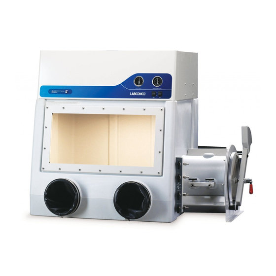
® Congratulations on your purchase of a Labconco Precise Controlled ® Atmosphere Glove Box or Precise Basic Glove Box manufactured with a one-piece molded polyethylene liner. The Precise Controlled Atmosphere Glove Box comes equipped with six valves, pressure relief valve and two chamber pressure gauge indicators, which are omitted from the Precise Basic Glove Box. -
Page 6: Chapter 2: Prerequisites
Before you install the glove box, you need to prepare your site for installation. You must be certain that the area is level and of solid construction. In addition, a dedicated source of electrical power should be located near the installation site to power the glove box. Additionally, the glove box should be strategically placed in the lab to provide efficient workflow and prevent operator interference from normal traffic flow. -
Page 7: Support, Vibration & Preventive Requirements
A bench or stand that is rigidly mounted to the floor or fixed to the wall, but not both, may be appropriate. 35" to 40" (889mm to 1,016mm) is typical for standing height (Labconco stands offered in Chapter 7 vary from 33" to 40" or 838mm to 1,016mm). -
Page 8: Electrical Requirements
4" diameter thimble duct connection to aid in the connection to the building exhaust blower preventing the pressure relief valve from activating due to the negative pressure of the building exhaust. Labconco offers accessory remote blowers listed in Chapter 7 for your convenience in venting the pressure relief to the outside. -
Page 9: Space Requirements
Chapter 2: Prerequisites optional drying train removal traps. The two valves on the transfer chamber are used for gas inlet and vacuum outlet lines. The transfer chamber lines can be connected together with the main chamber gas inlet and vacuum outlet lines to simplify gas and vacuum connections to both chambers. - Page 10 Once the site for your glove box is properly prepared, you are ready to unpack, inspect, install, and validate performance of your system. Read this chapter to learn how to: • Unpack and move the glove box. • Set up the glove box with the proper supporting structure and work surface.
-
Page 11: Chapter 3: Getting Started
THE UNITED STATES INTERSTATE COMMERCE COMMISSION RULES REQUIRE THAT CLAIMS BE FILED WITH THE DELIVERY CARRIER WITHIN FIFTEEN (15) DAYS OF DELIVERY. DO NOT RETURN GOODS WITHOUT THE PRIOR AUTHORIZATION OF LABCONCO. UNAUTHORIZED RETURNS WILL NOT BE ACCEPTED. Product Service 1-800-522-7658... -
Page 12: Installing The Glove Box On A Supporting Structure
Figure B-1 in Appendix B shows the location of the pressure relief valve without any optional vent kits. Labconco provides pressure relief exhaust kits, which exhaust to the outside. HEPA and/or carbon filtered exhaust kits are also available. - Page 13 Chapter 3: Getting Started To connect the Pressure Relief Vent Valve to an exterior exhaust system, order the Ventilation Kit (#5242700) and refer to Figure 3-1. To provide HEPA filtered exhaust to the room or outside, order the HEPA Filtered Pressure Relief Vent Kit (#5238500) and refer to Figure 3-2.
- Page 14 Chapter 3: Getting Started Figure 3-1 Pressure Relief Vent Kit (#5242700) Product Service 1-800-522-7658...
- Page 15 Chapter 3: Getting Started Figure 3-2 HEPA Filtered Pressure Relief Vent Kit (#5238500) Product Service 1-800-522-7658...
- Page 16 Chapter 3: Getting Started Figure 3-3 Carbon Filtered Pressure Relief Vent Kit (#5241200) Product Service 1-800-522-7658...
-
Page 17: Installation Of Gloves To The Glove Ports
Chapter 3: Getting Started Installation of Gloves to the Glove Ports With the thumbs up and in a right/left orientation, secure the gloves in place on the glove ports by stretching the beaded glove cuff into the glove port groove nearest the window. Install the separate 8" diameter O-ring over the gloves, into the outer groove of the glove port surface. -
Page 18: Connect The Plumbing Lines For Gas, Vacuum & Drying Train
Connect the Plumbing Lines for Gas, Vacuum, and Drying Train Labconco offers various vacuum and gas tubing installation kits listed in Chapter 7 for connecting gas and vacuum line, or drying train to the glove box. Refer to Figures 3-6, 3-7, 3-8, 3-9, and 3-10 that depict the installation tubing kits. - Page 19 Chapter 3: Getting Started Hose Connector Small Ferrule Alternative Method with Compression Nut Hose Connector Note: Hose Clamp not supplied. Tube Insert Large Ferrule Small Ferrule Primary Compression Nut Method for Tygon Tubing Figure 3-5 Close-up View of Typical Valve Connection Options Product Service 1-800-522-7658...
- Page 20 Chapter 3: Getting Started Figure 3-6 Typical Tubing Connections for Manual Valve Operation (Tubing Connection Kit 5245100 provides full details) Product Service 1-800-522-7658...
- Page 21 Chapter 3: Getting Started Figure 3-7 Typical Tubing Connections with Automatic Pressure Controller (Tubing Connection Kit 5245200 provides full details) Product Service 1-800-522-7658...
- Page 22 Chapter 3: Getting Started Figure 3-8 Typical Connections Shown with Connection to the Automatic Pressure Controller (Full details provided with Automatic Pressure Controller) Product Service 1-800-522-7658...
- Page 23 Chapter 3: Getting Started Figure 3-9 Typical Tubing Connections for Oxygen & Moisture Removal Shown with the Automatic Pressure Controller (Tubing Connection Kit 5242501 provides full details) Product Service 1-800-522-7658...
-
Page 24: Validating The Glove Box
Chapter 3: Getting Started Figure 3-10 Typical Tubing Connections for Dual Moisture/Solvent Removal System Shown with the Automatic Pressure Controller (Tubing Connection Kit 5242500 provides full details) Validating the Glove Box Each Precise Glove Box has been helium leak tested at the factory for integrity and found to have no leaks greater than 1 x 10 cc/sec while at a positive pressure of 5 inches helium. - Page 25 Chapter 3: Getting Started chambers. Figure 3-11 shows test results of the oxygen decay or oxygen level increase as a function of time. Per ISO specifications, Class 1 controlled atmosphere chambers have a specified hourly leak rate of less than 5 x 10 Table 3-1 listed at the end of Chapter 3.
-
Page 26: Oxygen Method Leak Testing Summary (Iso 10648-2)
Chapter 3: Getting Started Table 3-1 Classification of Glove Box Containment per ISO 10648-2 Class Hourly Leak Rate (T Usage Example ≤ 5 x 10 Controlled atmosphere with high inert gas purity conditions < 2.5 x 10 Controlled atmosphere under inert gas conditions or permanently hazardous atmosphere <... -
Page 27: Pressure Change Method Leak Testing Summary (Iso 10648-2)
Chapter 3: Getting Started Pressure Change Leak Testing Method Summary (ISO-10648-2) The method consists of measuring the pressure rise per unit time after establishing a negative pressure in the main chamber of the glove box. Use -1000 Pa for the acceptance test and -250 Pa for the operational test. The hourly leak rate includes adjustments for barometric pressure and temperature changes which can be calculated as T = (60/t) * ((PnT... -
Page 28: Safety Precautions
The Precise Controlled Atmosphere Glove Box is designed to meet the needs of the laboratory scientists requiring an inert atmosphere for sensitive ambient air operations. Labconco has engineered the Precise Controlled Atmosphere Glove Boxes to meet the ISO 10648-2 Class 1 atmosphere leak specification. - Page 29 Chapter 4: Performance Features and Safety Precautions Generally, 75-100 purge and fill cycles are required to reduce moisture and oxygen levels below 1% (see Appendix D). 100-150 purge and fill cycles will typically reduce moisture and oxygen levels to 0.3% or 3,000 ppm.
- Page 30 Chapter 4: Performance Features and Safety Precautions 11. Interior Switched Duplex is located on the glove box ceiling. The innermost outlet of the duplex labeled “AUX” is controlled by the switch located on the front control panel. The other outlet is on constantly when the glove box is connected to an electrical supply.
-
Page 31: Safety Precautions
Chapter 4: Performance Features and Safety Precautions Safety Precautions 1. It is the responsibility of the user to determine the suitability of this product for the intended applications. Consult your Safety Officer for application review. 2. Although the glove box has been engineered to maintain optimum operator safety, caution should always be used while working. - Page 32 Chapter 4: Performance Features and Safety Precautions 12. All powders, gases, and particulates removed by the operation of the vacuum pumps connected to this glove box are to be filtered and/or ducted to the outside. 13. Exhaust vacuum pumps should be filtered and/or ducted to the outside when using hazardous materials.
-
Page 33: Chapter 5: Using Your Glove Box
Now that the installation of your glove box is completed, you are ready to use Read this chapter to learn about: • Routine Daily Work Procedures. • Hazardous Use with Chemicals. • Prohibited Acid Use. Routine Daily Work Procedures Planning •... - Page 34 (see Appendix E). • Recirculating drying trains are required to further reduce and maintain oxygen and moisture levels below 1%. Labconco oxygen and moisture removal drying trains can maintain oxygen levels below 5 ppm and moisture levels below 50 ppm.
-
Page 35: Hazardous Use With Chemicals
The glove box life span will be limited with use of mineral acids. NOTE: Labconco makes no claims about life span of the glove box with mineral acid use and warranties will become void. Product Service 1-800-522-7658... -
Page 36: Chapter 6: Maintaining Your Glove Box
Review this chapter on maintenance for the following: 1. Routine maintenance. 2. Initial certification. 3. Recertification. 4. Fluorescent light replacement. 5. Pressure relief valve replacement. 6. Service valve and pressure gauge replacement. Routine Maintenance Schedule Weekly • Wipe down the interior surfaces of the glove box with a disinfectant or cleaner, depending upon the application. -
Page 37: Initial Certification
The glove box should be certified by your Safety Officer before use, with one of the two tests listed below under Recertification. See Appendix G for Labconco Helium Leak Test Method performed on all glove boxes at the factory. Recertification Under normal operating conditions, the glove box should be recertified at the time of installation and at least annually thereafter. -
Page 38: Service Valve And Pressure Gauge Replacement
Chapter 6: Maintaining Your Glove Box 7. Install the new pressure relief valve with the gasket to the inside. Tighten the large nut. 8. Turn the glove box ON and re-certify the glove box. 9. Refer to Appendix A, Appendix B and Chapters 3 and 7 for installation diagrams. -
Page 39: Chapter 7: Accessorizing Your Glove Box
2. 30" Standard Base Cabinet (Part #9900200) Two optional base cabinets can be ordered to support the 60" x 30" work surface and glove box. Contact Labconco for additional sizes. 3. Adjustable Height Base Stands with Attached Work Surface (Part #5235500 w/casters, Part #5235501 w/adjustable feet) These stands, 60"... - Page 40 Chapter 7: Accessorizing Your Glove Box separately. This kit can be used if additional valves are desired or valves are added to the Precise Basic Glove Box. For a complete installation of six valves, mounting brackets, pressure relief valve, and labels for the Precise Basic Glove Box, order Full Valve Kit #5232101.
- Page 41 Chapter 7: Accessorizing Your Glove Box Figure 7-1 All dimensions in inches 11. Pressure Relief Vent Kits and Pressure Relief Valve Pressure relief vent kits are detailed in Chapters 2 and 3 and include tubing connections and/or filters. Three pressure relief vent kits are available to vent either unfiltered air or filtered air.
- Page 42 Chapter 7: Accessorizing Your Glove Box 13. Automatic Pressure Controller The Pressure Controller allows the end user the convenience of automatically regulating pressure and vacuum within the glove box main chamber and transfer chamber. The end user can also automate the purge/fill cycles up to 199 cycles for each chamber.
- Page 43 Chapter 7: Accessorizing Your Glove Box 14. Filtration Components for Moisture, Oxygen and Fume Removal The following components can be used to remove organics, acids, ammonia, oxygen, moisture and other gases as indicated. They are connected to the two auxiliary valves on the main glove box chamber for recirculation of main chamber atmosphere and contaminant removal of air (see Figures 3-9 and 3-10).
- Page 44 Chapter 7: Accessorizing Your Glove Box 18. Moisture Monitors/Hygrometers Moisture monitors or hygrometers allow the user to continuously monitor moisture levels inside the glove box. All moisture monitors are placed inside the main chamber. Never operate a transfer chamber vacuum purge on these sensitive hygrometers as damage can occur.
- Page 45 Chapter 7: Accessorizing Your Glove Box 24. IV Bar Kit (Part #5242100) Provides a bar for hanging IV bags or tools. Must be used with one of the interior storage shelf kits (5235000 or 5235001). 25. Gloves (see Appendix A: Replacement Part numbers for other glove sizes and material types) Neoprene gloves are the most resistant to abrasion and tearing.
-
Page 46: Chapter 8: Electrical System Troubleshooting
Refer to the following table if your glove box fails to operate properly. If the suggested corrective actions do not solve your problem, contact Labconco for additional assistance. The Precise Controlled Atmosphere Glove Box and Precise Basic Glove Box have only two electrical circuits. -
Page 47: Appendix A: Replacement Parts
The components that are available for your glove box are listed. The parts shown are the most commonly requested. If other parts are required, please contact Product Service. Item Qty. Part Description Number 5232200 Framed Glass Window (standard) 5236100 Framed Acrylic Window (optional) 1230700 Receptacle, 115V Duplex 1283900... - Page 48 Appendix A: Replacement Parts Figure A-1 Replacement Parts for Precise Glove Boxes (Precise Controlled Atmosphere Glove Box Shown) Product Service 1-800-522-7658...
-
Page 49: Appendix B: Dimensions
See the following dimensions for all the glove boxes. Precise Controlled Atmosphere shown. All dimensions in inches. Figure B-1 Note: Six valves, pressure relief valve, and two pressure gauges are omitted on the Precise Basic Glove Box. Product Service 1-800-522-7658... -
Page 50: Appendix C: Specifications
This Appendix contains technical information about all the glove boxes including electrical specifications and environmental operating conditions. • 8 Amps, 115V or 4 Amps, 230V, 50/60 Hz or 8 Amps, 100V, 50/60 Hz, Precise Glove Box. Environmental Conditions • Indoor use only. •... - Page 51 & & % Oxygen Level Per Number of Purge and Fill Cycles Precise CA 1, 20.3% Glove Box Data Points = 5, 18.1% Number of cycles, % Oxygen 10, 15.1% 15, 12.6% 20, 10.5% 25, 8.8% 30, 7.4% 35, 6.2% 40, 5.2% 45, 4.4% 54, 3.2%...
-
Page 52: Purge & Fill Reduction Rates
Appendix D: Purge & Fill Reduction Rates % Moisture Level Per Number of Purge and Fill Cycles 1, 22.1% Precise CA Glove Data Points = 5, 19% Number of cycles, % Water 10, 15.8% 15, 13.2% 20, 11% 25, 9.1% 30, 7.5% 35, 6.2% 42, 5%... - Page 53 & & Note: Precise Glove Box Volume is 13 cu. ft. or 368 liters; 3000ppm or 0.3% of 368 liters = 1.1 liters of oxygen initially used Glove Box Initial Oxygen Catalog# 5244200 Total Oxygen Total Oxygen Number Main Chamber Pressure Oxygen Leak Rate Capacity Used Oxygen Column Life...
- Page 54 Appendix E: Life Span for Oxygen Removal Column & Moisture Moisture/Oxygen Leak Rate @ -1, 0, +1 Box Pressure Moisture -1 2.9 ppm/min Moisture 0 1.7 ppm/min Moisture +1 1.6 ppm/min Oxygen -1 0.52ppm/min Oxygen 0 0.22 ppm/min Oxygen +1 0.15 ppm/min Time (Minutes) Product Service 1-800-522-7658...
- Page 55 Static Electricity Test The tests were performed by monitoring the level of static electricity found on the work surface and interior surfaces within the glove box. Static electricity levels were measured with an AlphaLab Surface DC Voltmeter http://scientificmeter.com/surface_dc.htm A DESCO Emit Mini Zero Volt Ionizer http://www.descoemit.com/ViewProduct.aspx?pid= was installed in the glove box.
-
Page 56: Appendix F: Ionizer Fan Performance Criteria
Appendix F: Ionizer Fan Performance Criteria Test Point Locations and Voltage Levels Metal Metal Metal Back Left Right Interior Center Housing Housing Transfer Interior Interior Interior Lamp Work Inlet Exhaust Chamber Surface Surface Surface Window Surface HEPA HEPA Handle + 420 + 220 + 734 + 375... -
Page 57: Appendix G: Helium Leak Test Method
Purpose The purpose of this test is to assure that all gasketed joints and seams of the enclosure are helium leak tight. Test Setup 1. Connect one of the valves to a vacuum pump. 2. Connect the other valve to a helium supply tank regulated between 10 and 15 PSI. - Page 58 Precise Controlled Atmosphere Glove Boxes. Other Equipment 1. For a less critical helium leak measurement using a lower cost leak detector, Labconco recommends using Restek (www.restek.com) or other instrumentation available from a laboratory supply dealer. Product Service 1-800-522-7658...
-
Page 59: Appendix H: Plumbing Diamgrams
Product Service 1-800-522-7658... - Page 60 Appendix H: Plumbing Diagrams Product Service 1-800-522-7658...
-
Page 61: Appendix I: Pressure & Flow Rate Conversions
Pressure Conversions mmHg in.Hg in.H ft.H lb/in. Kg/cm From mmHg .03937 .5353 .04461 .00132 .01934 .00136 .1333 .0013 in.Hg 25.40 13.60 1.133 .03342 .4912 .03453 3.387 .0339 1.868 .07355 .08333 .00246 .03612 .00254 .2490 .0025 in.H ft.H2O 22.42 .8826 .02950 .4334 .03048 2.988... -
Page 62: Appendix J: References
Many excellent reference texts and booklets are currently available. The following is a brief listing: Pharmaceutical Isolators, A Guide to their application design and control. Pharmaceutical Press 2004, Editors: Midcalf, Phillips, Neiger, and Coles. Isolation Technology, A Practical Guide, 2004 CRC Press, 2 Edition, www.crcpress.com International Standard ISO 10648-2 Containment Enclosures... -
Page 63: Declaration Of Conformity
I, the undersigned, hereby declare that the equipment specified above conforms to the above Directive(s) and Standard(s). See individual Declaration of Conformity which will be signed by the importer for your country. Place: _______________________________________ (Signature) Date: _______________________________________ (Full Name) _______________________________________ (Position) Labconco P/N 36960-60 REV B, ECO E026 Product Service 1-800-522-7658...
Need help?
Do you have a question about the Precise CA 5220100 and is the answer not in the manual?
Questions and answers