Sign In
Upload
Manuals
Brands
Labconco Manuals
Laboratory Equipment
Axiom C1
Labconco Axiom C1 Biosafety Cabinet Manuals
Manuals and User Guides for Labconco Axiom C1 Biosafety Cabinet. We have
2
Labconco Axiom C1 Biosafety Cabinet manuals available for free PDF download: Technical Manual, User Manual
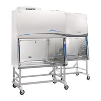
Labconco Axiom C1 Technical Manual (201 pages)
Biosafety Cabinets, Procedure Stations
Brand:
Labconco
| Category:
Laboratory Equipment
| Size: 9 MB
Table of Contents
Table of Contents
4
1: Introduction
11
Contacting Labconco
11
About this Manual
12
Theory of Operation
12
Type A2
12
Type B2
13
Type C1 - a Mode
13
Type C1 - B Mode
14
2: Safety Precautions
15
Typographical Conventions
15
General Safety Precautions
17
Safety Precautions for this Product
19
3: Catalog Number Configurator
21
4: Serial Tag
22
Serial Tag Location
22
Serial Tag Information
23
Primary Serial Tag
23
Secondary Serial Tag
23
5: Factory Test Report
24
Test Report Location
24
Test Report Information
25
6: Additional Product Information
26
Data Plate Location
26
Data Plate Information
27
7: Exhaust System Connections
28
Exhaust Connection Best Practices
28
Air-Tight Damper
30
Exhaust System Requirements
31
Type A2 Models
31
Cell Logic+ Type A2 Models
32
Type B2 Models
32
Type C1 Models
33
8: Configuration
34
Current Configuration
34
Change Configuration
36
9: Calibration
40
Certifier Password
40
Adjusting Blower Speed
41
Adjusting the Internal Air Damper
43
Setting the Filter Life Gauge
45
Type A2 (8-Inch through 10-Inch Sash) and Type B2
45
Type A2 (12-Inch Sash) and Type C1
46
Airflow Sensor Calibration
47
Type A2 and Type C1
47
Type B2
48
Zero Point Calibration
50
Vacuum Start Switch Calibration (Type C1 Only)
51
10: Certification
53
Certifier Password
53
Type A2 HEPA Filter Leak Test Preparation
53
Theoretical Upstream Concentration
54
Upstream Concentration Sampling
54
Type A2 Supply HEPA Filter Leak Test
56
Acceptance Criteria
57
Type A2 Exhaust HEPA Filter Leak Test
58
Acceptance Criteria
59
Type B2 Supply HEPA Filter Leak Test Preparation
60
Theoretical Upstream Concentration
60
Upstream Concentration Sampling
60
Type B2 Supply HEPA Filter Leak Test
62
Acceptance Criteria
63
Type B2 Exhaust HEPA Filter Leak Test Preparation
64
Theoretical Upstream Concentration
64
Type B2 Exhaust HEPA Filter Leak Test
65
Acceptance Criteria
65
Type C1 Supply HEPA Filter Leak Test Preparation
66
Theoretical Upstream Concentration
66
Upstream Concentration Sampling
66
Type C1 Supply HEPA Filter Leak Test
68
Acceptance Criteria
69
Type C1 Exhaust HEPA Filter Leak Test Preparation
70
Theoretical Upstream Concentration
70
Type C1 Exhaust HEPA Filter Leak Test
72
Acceptance Criteria
73
Downflow Velocity
74
Acceptance Criteria
75
Inflow Velocity
76
Primary Method
76
Acceptance Criteria
78
Secondary Method
79
Acceptance Criteria
83
Work Area Air Cleanliness Test (Optional)
84
Acceptance Criteria
84
Lighting Test (Optional)
85
Acceptance Criteria
85
Noise Test (Optional)
86
Acceptance Criteria
86
Vibration Test (Optional)
86
UV Light Intensity Test (Optional)
87
Acceptance Criteria
87
Ground Fault Circuit Interrupter (GFCI) Test
88
Acceptance Criteria
88
11: Quickcharts
89
Quickchart - Type A2 3-Ft & 4-Ft
90
Quickchart - Type A2 5-Ft & 6-Ft
91
Type A2 Footnotes
92
Quickchart - Type B2
93
Type B2 Footnotes
94
Quickchart - Type C1
95
Type C1 Footnotes
96
12: Advanced Service Procedures
97
Tools
97
Required
97
Optional
97
Removal of External Dress Panels
98
Dress Panel
98
Side Panels
99
Front Sash
100
Sash Level Adjustment
100
Sash Sensor Adjustment or Replacement
101
HEPA Filter Replacement
104
Type A2 (8, 9, 10-Inch Sash)
104
Type A2 (12-Inch Sash)
107
Type B2
110
Type C1
114
Blower/Motor Replacement
117
Type A2 (8, 9, 10-Inch Sash) & B2
117
Type A2 (12-Inch Sash) & C1 Supply Blower/Motor
121
Type A2 (12-Inch Sash) & C1 Exhaust Blower/Motor
124
Changing the LED Lamps
129
LED Lamp Socket Cap Replacement
131
Changing the Optional UV Lamp
132
UV Lamp Socket Replacement
133
Type B2 Prefilter Replacement
134
Air-Tight Damper Adjustment
135
Preparing the Biosafety Cabinet for Gaseous Sterilization
136
Service Fixture Installation & Service Connection
137
13: Electrical Components
140
Electronics Module
140
Electronic Module Components
141
Resetting a Circuit Breaker
142
Power Supply Board
143
Display Board
144
Speaker
145
Blower Motor
146
Wiring Diagrams
148
100-115V
148
208-240V
149
14: Troubleshooting
150
Blower and Lights Not Working
150
Blower Only will Not Start
151
Lights Only will Not Illuminate
152
UV Light will Not Illuminate
153
Airflow Alert Activating
154
Filter Life Gauge Not at 100% When New
155
Contamination in the Work Area
156
15: Diagnostics
157
Sash Sensors
157
Keypad
158
Airflow Sensor (Optional)
159
Canopy (Optional)
160
16: Bms Data Output Connection
161
Connection Type
161
Data Output Format
162
Data Output Rate
162
Data Output String Definition
163
Data Output Software Requirements
164
17: Ventus Canopy Connection Kit
165
Kit Catalog Numbers
166
Installation Procedure
166
Exhaust Damper Installation Procedure
168
Canopy Switch Wiring Connection
168
Calibrate for Operation
169
18: Airflow Sensor Kit
171
Installation - Type A2 Without Ventus Canopy
171
Installation - Type A2 with Ventus Canopy
173
Connection to Electronics Module
175
Configuration (New Install Only)
176
Calibration
178
19: Uv Lamp Kit
181
Kit Catalog Numbers
181
Installation
181
Configuration
183
20: IV Bar Kit
185
Kit Catalog Numbers
185
Installation
185
21: Prefilter Kit
187
Kit Catalog Numbers (Type A2 and B2 Only)
187
Installation
187
Attach Prefilter(S) to Towel Catch - G4 Paper
188
Attach Prefilter(S) to Towel Catch - Aluminum Washable
189
22: en Alarm/Relay Contact Kit
190
Installation
190
Example 1 - Blower Relay Contact (Single Phase AC)
194
Example 2 - Blower Relay Contact (Three Phase AC)
195
23: Parts List
196
Type A2 Consumables
196
Type B2 Consumables
197
Type C1 Consumables
198
Advanced Service Components
199
Advertisement
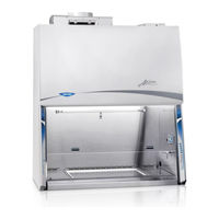
Labconco Axiom C1 User Manual (86 pages)
Brand:
Labconco
| Category:
Laboratory Equipment
| Size: 4 MB
Table of Contents
Table of Contents
4
1 : Introduction
9
About this Manual
9
Contents Included
9
2 : before You Install
10
Location Requirements
10
Clearance Requirements
11
Electrical Requirements
11
Service Line Requirements
11
Exhaust Requirements
12
Air-Tight Damper
14
3 : Safety Precautions
15
Typographical Conventions
15
General Safety Precautions
17
Safety Precautions for this Product
19
4 : Installation
21
Unpacking
21
Electrical Connection
26
Service Line Connection
27
Exhaust Connection
28
Drain Valve Installation (Optional)
29
Certification
31
5 : Performance Features
32
Laminar Airflow
32
Directional Airflow
33
Cabinet Air Intake (Front Grille)
33
Chem-Zone TM Directly Exhausted Work Zone
34
HEPA Filters
34
ULPA Filters
35
Motor/Blower
36
UV Lamp (Optional)
37
6 : Mylogic Operating System
38
Home Screen
38
Display Sleep Mode
39
Keypad
39
Main Menu
40
Configuration Submenu
41
Audible Tones
41
Selecting a Language
41
Setting the Clock
42
Setting Automatic Operation Options
43
Tm Tm
43
TM / Smartstart TM )
43
Navigating the Settings Submenu
44
Selecting the Units of Measure
44
Activating the Security Lock
44
Setting the USB Output Rate
44
UV Parameters
45
The Tools Submenu
45
Timer Operation
46
Interval Timer Operation
46
Stopwatch Timer Operation
46
Airflow Alert
47
Resetting the Airflow Alert System
47
Alarms
48
Power Loss Alarm
48
Sash Height Alarm
48
Blower Failure Alarm
48
Exhaust Airflow Check
49
Starting Exhaust Alarm
49
Running Exhaust Alarm - Active Protection
49
Overdriven Exhaust Alarm
50
7 : Using Your Axiom Type C1
51
Feature Overview
51
System Reset Switch
52
Keypad
53
Sash Operation
54
Blower Operation
54
Light Operation
54
Outlet Operation
54
Vacu-Pass TM Cord & Cable Pass Thru (Optional)
55
Working in the Cabinet
56
Planning
56
Cabinet Start-Up
56
Wipe down
56
Loading Materials and Equipment
57
Work Techniques
57
Final Purging
57
Unloading Materials and Equipment
57
Wipe down
57
Shutdown
58
8 : Maintaining Your Axiom Type C1
59
Maintenance Safety Precautions
59
Recommended Maintenance Schedule
60
Service Operations
61
Resetting a Circuit Breaker
61
Center Work Surface Removal
62
Wing Work Surface Removal
63
Center Drip Tray Removal
64
Front Grille Removal
64
Front Panel Removal
65
Changing the LED Lamps
66
Changing the Optional UV Lamp
68
Storage
69
9 : Accessories
70
Telescoping Base Stands
70
Manual or Electric Hydraulic Lift Base Stands
70
Solo TM Electric Hydraulic Lift Base Stands
71
IV Bar
71
Flat Work Surface
71
Airflow Sensor
72
Bag in Bag out Exhaust HEPA Filter
72
Sash Prop
73
10 : Troubleshooting
74
Blower and Lights Not Working
74
Blower Only will Not Start
75
Lights Only will Not Illuminate
76
UV Light will Not Illuminate
77
Airflow Alert Activating
78
Filter Life Gauge Not at 100% When New
79
Contamination in the Work Area
80
Appendix A: Parts List
81
Appendix B: Dimensions
83
Appendix C: Specifications
84
Advertisement
Related Products
Labconco CentriVap-105 Cold Trap
Labconco Precise CA 5220100
Labconco Precise CA 5220120
Labconco Precise CA 5220121
Labconco Precise CA 5220130
Labconco Precise CA 5220131
Labconco CentriVap DNA Systems
Labconco Intelli-Sense CS 10
Labconco Intelli-Sense CS 12
Labconco 37400-00
Labconco Categories
Laboratory Equipment
Ventilation Hood
Enclosure
Dryer
Fan
More Labconco Manuals
Login
Sign In
OR
Sign in with Facebook
Sign in with Google
Upload manual
Upload from disk
Upload from URL