Labconco Purifier Axiom 30441 Series User Manual
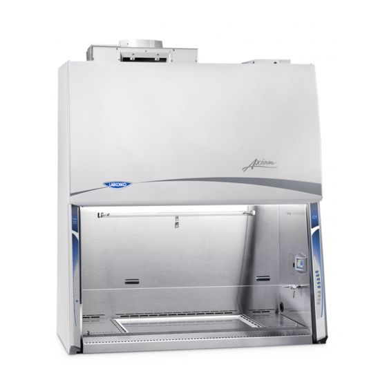
Biological safety cabinet
Hide thumbs
Also See for Purifier Axiom 30441 Series:
- Technical manual and specifications (164 pages)
Table of Contents
Advertisement
Quick Links
TYPE
C1
User's Manual
Purifier
Biological Safety Cabinets
30441 Series
30461 Series
To receive important product updates,
complete your product registration card
online at register.labconco.com
Please read the User's Manual before operating the equipment.
®
Models
30448 Series
30468 Series
Labconco Corporation
8811 Prospect Avenue
Kansas City, MO 64132-2696
800-821-5525, 816-333-8811
FAX 816-363-0130
E-MAIL
HOME PAGE www.labconco.com
Original instructions
labconco@labconco.com
Advertisement
Table of Contents

Related Manuals for Labconco Purifier Axiom 30441 Series


Summary of Contents for Labconco Purifier Axiom 30441 Series
- Page 1 Biological Safety Cabinets Models 30441 Series 30448 Series 30461 Series 30468 Series To receive important product updates, complete your product registration card online at register.labconco.com TYPE Labconco Corporation 8811 Prospect Avenue Kansas City, MO 64132-2696 800-821-5525, 816-333-8811 FAX 816-363-0130 E-MAIL labconco@labconco.com...
- Page 2 Original instructions This page is intentionally blank.
- Page 3 Warranty Labconco Corporation provides a warranty to the original buyer for the repair or replacement of parts and reasonable labor as a result of normal and proper use of the equipment with compatible chemicals. Broken glassware and maintenance items, such as filters, gaskets, light bulbs, finishes and lubrication are not warranted.
-
Page 4: Table Of Contents
Unpacking the Biosafety Cabinet Moving and Lifting the Biosafety Cabinet Installing the Biosafety Cabinet on an Existing Work Surface Installing the Biosafety Cabinet on a Labconco Base Stand Telescoping Base Stands Manual or Electric Hydraulic Lift Base Stands SoLo™ Electric Hydraulic Lift Base Stands... - Page 5 Original instructions Cabinet Air Intakes (Grilles) Ultraviolet (UV) Lamp Safety Precautions CHAPTER 5: USING THE CABINET System Reset Switch Blower Startup Sequence Information Center Alarm Screens Operating the Sliding Sash Starting the Biosafety Cabinet The Axiom Touchpad Navigating the Axiom Menu Screens Navigating the MyLogic Menu Screens Setting the Clock...
- Page 6 Original instructions CHAPTER 7: TROUBLESHOOTING APPENDIX A: COMPONENTS APPENDIX B: DIMENSIONS APPENDIX C: SPECIFICATIONS Electrical Data Motor Specifications Environmental Conditions APPENDIX D: ACCESSORIES APPENDIX E: QUICK CHART CAUTION – See Manual. When this symbol is on the unit it indicates a caution that is detailed in this manual. ATTENTION - Voir manuel.
-
Page 7: Chapter 1: Introduction
Original instructions Chapter 1: Introduction ® ® Congratulations on the purchase of a Labconco Purifier Axiom Biosafety Cabinet. The biosafety cabinet is designed to protect you, the product and the laboratory environment from biohazardous aerosols. The Axiom is the result of years of experience in manufacturing biohazard cabinetry, and users like you suggested many of its features. -
Page 8: Chapter 2: Prerequisites
Original instructions Chapter 2: Prerequisites Before you install the Axiom, you need to prepare the site for installation. Examine the location where you intend to install the cabinet. You must be certain that the area is level and of solid construction. In addition, a dedicated source of electrical power must be located near the installation site. -
Page 9: Location Requirements
Original instructions Chapter 2: Prerequisites Location Requirements Note: The biosafety cabinet should be located away from traffic patterns, doors, fans, ventilation registers, fume hoods and any other air-handling devices that could disrupt its airflow patterns. All windows in the room should remain closed. -
Page 10: Exhaust Requirements
Original instructions Chapter 2: Prerequisites If you intend to connect the biosafety cabinet to an exhaust system: Figure 2-1b NOTE: Only connect the cabinet to a suitable exhaust system, one dedicated to the cabinet itself, or dedicated to exhausting laboratory ventilation equipment. - Page 11 Original instructions Chapter 2: Prerequisites Figure 2-1e If additional room exhaust is needed to be drawn through the exhaust system, install an additional duct and balancing damper downstream of the cabinet’s damper. This will allow for proper balancing of the system. The exhaust system must be capable of moving the following volumes of exhaust air at the negative pressures listed.
-
Page 12: Electrical Requirements
Note: On 100 and 115 VAC models, both electrical outlets are protected by a ground fault interrupter circuit (GFIC). Labconco does not recommend plugging the biosafety cabinet into a GFIC outlet. Electrical outlets in the cabinet are restricted to 5 amps maximum current. -
Page 13: Service Line Requirements
Original instructions Chapter 2: Prerequisites Service Line Requirements All utility service lines should be ¼ inch O.D., brass, copper, or stainless steel, and equipped with an easily accessible shut-off valve. The service valves are rated for operation at 40 PSI (275 kPa). If the service line pressure exceeds this, it must be equipped with a pressure regulator to reduce the line pressure. -
Page 14: Chapter 3: Getting Started
Original instructions Chapter 3: Getting Started Now that the installation is properly prepared, you are ready to inspect, install, and certify the Axiom biosafety cabinet. This chapter covers how to: Unpack and move the biosafety cabinet. Install the cabinet. ... -
Page 15: Unpacking The Biosafety Cabinet
Unauthorized returns will not be accepted. If the cabinet was damaged in transit, you must file a claim directly with the freight carrier. Labconco Corporation and its dealers are not responsible for shipping damages. Do not discard the carton or packing material for the biosafety cabinet until all of the components have been checked, installed and tested. -
Page 16: Installing The Biosafety Cabinet On An Existing Work Surface
Installing the Cabinet on a Labconco Base Stand Labconco offers accessory Base Stands in a variety of configurations to suit your particular needs. Stands can be ordered with adjustable telescoping legs or with a manually or electrically adjustable hydraulic lift. -
Page 17: Solo Electric Hydraulic Lift Base Stands
3780337 3780341 Preparing the Biosafety Cabinet for Operation Installation instructions (Labconco P/N 1056801) are attached to the sash of the biosafety cabinet. If these instructions are missing or unclear, contact Product Service at 800-821-5525 or 816-333-8811. The following are located in a box either underneath or secured to the work surface: ... -
Page 18: Connecting The Biosafety Cabinet To Utility Service Lines
Original instructions Chapter 3: Getting Started Connecting the Biosafety Cabinet to Utility Service Lines Note: Some models have a solenoid valve connected to the service valve on the right side, rear position. The solenoid prevents gas from flowing to the service valve when the unit blower is off. -
Page 19: Optional Exhaust Connection Requirements
Prerequisites Note: If the research involves the use of toxic compounds or volatile materials, contact the facility’s safety officer or Labconco to ensure that the biosafety cabinet and its exhaust system are compatible with the materials you will be working with. -
Page 20: Exhaust Connection Configuration
Original instructions Chapter 3: Getting Started Exhaust Connection Configuration Note: The Axiom is configured at the factory to operate unconnected to an exhaust system. When operating in this mode, the cabinet ignores the inlet relief valve position. If you intend to connect the cabinet to an exhaust system, YOU MUST RECONFIGURE IT FOR THIS INSTALLATION. -
Page 21: Selecting The Configuration Menu
Original instructions Chapter 3: Getting Started b) Electronic configuration Keypad operations are shown as blue bold italic. Menu screen selections are shown as green italics. 1. With the unit in operation, access the menu by pressing the Menu button. The display panel will show the first level menu. Select ▲... - Page 22 The interval can be programmed from 0-300 seconds. Note: Consult with your facility’s safety officer or Labconco to help establish how long the Axiom should continue to operate after an exhaust system failure.
- Page 23 Original instructions Chapter 3: Getting Started 7. The fourth screen allows you to select whether the Axiom has a UV light or not. IT IS CRITICAL THAT THE YOU LEAVE THE UV LIGHT CONFIGURATION AS IT WAS SET AT THE FACTORY.
-
Page 24: Disconnecting The Axiom From An Exhaust System
Original instructions Chapter 3: Getting Started Disconnecting the Axiom from an Exhaust System c) Mechanical configuration 1. Using an appropriate ladder or platform, remove the exhaust cover panel(s) on the top left side of the exhaust cover, and install them on the studs on the right side. Hand tighten the wing nuts to secure it, as shown in figure 3-2a. -
Page 25: Selecting The Configuration Menu
Original instructions Chapter 3: Getting Started d) Electronic configuration Keypad operations are shown as blue bold italic. Menu screen selections are shown as green italics. 1. With the unit in operation, access the menu by pressing the Menu button. The display panel will show the first level menu. Select ▲... - Page 26 Original instructions Chapter 3: Getting Started 3. The screen will now prompt you for the password; it is: Light UV Light Timer Timer Note: Any other key sequence will return you to the Attention screen. 4. The first screen allows you to select whether the Axiom is connected to an exhaust system or not.
-
Page 27: Optional Vacu-Pass Tm Cord And Cable Portal Use
Original instructions Chapter 3: Getting Started Optional Vacu-Pass Cord & Cable Portal Use Note: There must be enough clearance to pass the cord or cable between the Axiom’s exterior dress panel and any obstruction. Note: Some Vacu-Pass components and the cord or cable passing through it may become contaminated during use of the cabinet. -
Page 28: Drain Valve Installation
Original instructions Chapter 3: Getting Started Drain Valve Installation In order to prevent damage during shipping, the drain valve assembly has not been installed. If desired, the valve should be installed after the cabinet is in its final location. To install the valve assembly, follow these steps: Note: The work surface is heavy. -
Page 29: Initial Certification
*These tests are user comfort related tests and may be omitted at the user’s or certifier’s discretion. If you have any questions regarding certification agencies or need assistance in locating one, contact Labconco’s Product Service Department at 1-800- 522-7658 or 816-333-8811. Product Service 1-800-522-7658... -
Page 30: Chapter 4: Performance Features And Safety Precautions
Original instructions Chapter 4: Performance Features and Safety Precautions The Type C1 Purifier Axiom Biosafety Cabinet operates using the following principles: Filtration and retention of particulates by High Efficiency Particulate Air (HEPA) filter(s) Laminar airflow Directional airflow ... -
Page 31: Hepa Filters
Original instructions Chapter 4: Performance Features and Safety Precautions HEPA Filters HEPA filters are disposable, dry-type particulate filters. The filter material or media is typically made of borosilicate microfibers formed into a thin sheet, in a process similar to the production of paper. This sheet is folded, or pleated to increase its surface area. -
Page 32: Laminar Airflow
Original instructions Chapter 4: Performance Features and Safety Precautions Laminar Airflow Laminar airflow is defined as the movement of a body of air in a single direction, with a uniform velocity. In practice, the laminar downflow of air in the cabinet captures any aerosol generated in the work area of the cabinet, and directs it to the HEPA filters. -
Page 33: Directional Airflow
Original instructions Chapter 4: Performance Features and Safety Precautions Directional Airflow Directional airflow also plays a key role in biosafety cabinet performance. Air is drawn into the front of the cabinet at the front grille. This “curtain” of air makes it more difficult for aerosols to escape out of the work area of the cabinet and into the outside environment. -
Page 34: Chem-Zone Directly Exhausted Work Zone
Original instructions Chapter 4: Performance Features and Safety Precautions Chem-Zone Directly Exhausted Work Zone Unique to the Axiom is the Chem-Zone, a directly exhausted work zone. The central portion of the work surface is surrounded by grilles on the sides, front and back. -
Page 35: Motor/Blowers
The motors utilize Labconco’s exclusive Constant Airflow Profile (CAP) programming to deliver a consistent volume of air, throughout the life of the HEPA filters. -
Page 36: Cabinet Air Intakes (Grilles)
Original instructions Chapter 4: Performance Features and Safety Precautions Cabinet Air Intakes (Grilles) The location, size, and pattern of the grilles in the work area affect cabinet containment and performance. Note: Do not block or obstruct the grilles of the biosafety cabinet. Ultraviolet (UV) Lamp The optional UV lamp generates a primary wavelength of light of 254nm. -
Page 37: Safety Precautions
HEPA filter during installation or normal operation. If you suspect that a HEPA filter has been damaged, DO NOT use the cabinet; contact a local certification agency or Labconco at 800-821-5525 or 816-333- 8811 for re-certification information. The HEPA filters in the biosafety cabinet will gradually accumulate airborne particulate matter from the room and from work performed in the cabinet. - Page 38 Original instructions Chapter 4: Performance Features and Safety Precautions operating time and the nature of work being done in the cabinet. The Filter Gauge accurately displays the amount of filter life remaining. Proper operation of the cabinet depends largely upon its location and the operator’s work habits.
-
Page 39: Chapter 5: Using The Cabinet
Original instructions Chapter 5: Using the Cabinet System Reset Switch The biosafety cabinet has a system reset switch for resetting its microprocessors. The switch is located on the front of the electronics module, on top of the cabinet, as shown in Figure 5-1. Ensure that the switch is in the “ON”... -
Page 40: Information Center
Original instructions Chapter 5: Using The Cabinet Information Center The Information Center is an LCD display located on the right side wall at eye level. When the blower is started, if the Axiom is configured to be connected to an exhaust system, Figure 5-2a will appear for 60 seconds while the unit initiates operation. -
Page 41: Alarm Screens
Original instructions Chapter 5: Using The Cabinet Alarm Screens Figure 5-4a Sash is too high The sash is open too far for safe operation. Figure 5-4b Airflow Alerts The airflow patterns in the cabinet have changed, resulting in a sudden change in either motor speed. This is most likely due to a blockage of the grille or the exhaust filter outlet. -
Page 42: Operating The Sliding Sash
Original instructions Chapter 5: Using The Cabinet Operating the Sliding Sash The counterbalanced, anti-racking sash mechanism requires only a few pounds of force to move the sash up or down. You can open or close the sash smoothly with one or two hands positioned on either handle. The sash position alarm and safety interlock system senses the sash position and acts appropriately. -
Page 43: The Axiom Touchpad
Original instructions Chapter 5: Using The Cabinet The Axiom Touchpad The touchpad of the Axiom is shown in Figure 5-6. Take a moment to get familiar with the buttons, their locations and functions. Also familiarize yourself with the display located on the right side wall. The display will report system functions, such as filter capacity, timer displays, alarm or error messages, as well as icons that illuminate when cabinet functions such as UV light and blower are operational. -
Page 44: Navigating The Axiom Menu Screens
Original instructions Chapter 5: Using The Cabinet Navigating the Axiom Menu Screens MyLogic allows you to use the Smart-Start or Night-Smart features that activate functions automatically when the sash is opened or closed. Night- Smart will only work if the cabinet is not connected to an exhaust system. If equipped, the UV lamp can be programmed to operate for a given time interval when the sash is closed, before it shuts off. -
Page 45: Navigating The Mylogic Tm Menu Screens
Original instructions Chapter 5: Using The Cabinet Navigating the MyLogic Menu Screens The MyLogic screens will allow you to set the cabinet’s clock, and to personalize its operation. Please note all MyLogic screens have a blue background. Setting the Clock ▲... -
Page 46: Configuring The Axiom
Original instructions Chapter 5: Using The Cabinet Configuring the Axiom ▲ ▼ In the first MyLogic screen, use the buttons on the touchpad to highlight configure my Axiom for use -it will turn white when selected. Press to enter the first configuration screen: The first screen gives you the option of activating the Smart-Start option for the blower;... -
Page 47: Navigating The Settings Menu Screens
Original instructions Chapter 5: Using The Cabinet If you choose to use Night-Smart option for the UV lamp, this screen allows you to control the time the UV lamp will remain on after the sash ▲ ▼ is closed. Use the buttons on the touchpad to cycle through the time intervals available, and then press... -
Page 48: Startup Tone
Original instructions Chapter 5: Using The Cabinet Startup tone ▲ ▼ Using the buttons on the touchpad, highlight the Startup Tone option-it will turn white ▲ when selected, and then press OK. Using the ▼ buttons on the touchpad, highlight either Turned Turned off option. -
Page 49: Uv Settings
Original instructions Chapter 5: Using The Cabinet UV Settings For models equipped with the optional UV light the Axiom has an integral UV light maintenance system. It allows you to define how many hours you want the UV lamp to operate before receiving a reminder to replace it, a way to monitor how many hours the lamp has been on, and the means to reset the UV lamp hourmeter. -
Page 50: Change Uv Lamp Life
Service Menu screens that can alter the performance of the Axiom are password protected. If you have any questions about these screens, contact Labconco’s Product Service Department at 1-800-821-5525 or www.labconco.com for assistance. -
Page 51: Stopwatch Timer Operation
Original instructions Chapter 5: Using The Cabinet 4. When the timer reaches 0:00:00, an audible alarm will sound, and the timer will reset itself and repeat the countdown. 5. Press the button to pause the timer. 6. Press the Menu button to clear the interval timer and return to the main timer menu. - Page 52 Original instructions Chapter 5: Using The Cabinet Allow the cabinet to operate until the display screen is shown. Warm up screen- Connected to an exhaust system no exhaust system 10:03 Display screen Wash hands and arms thoroughly with germicidal soap. ...
- Page 53 Original instructions Chapter 5: Using The Cabinet Work Techniques If your work involves volatile toxic chemicals or radionuclides, ensure that the Type C1 is connected to an operational exhaust system, and is properly configured. Keep these materials in the center work area, so that any air flowing over these materials will be directed to the exhaust HEPA filter and out of the lab.
- Page 54 Original instructions Chapter 5: Using The Cabinet Inspect and clean the towel catch located at the rear of the work area, beneath the work pan. Dispose of rubber gloves appropriately, and have lab coat laundered properly. Wash hands and arms thoroughly with germicidal soap. Shutdown ...
-
Page 55: Chapter 6: Maintaining The Cabinet
Biosafety Cabinets. This manual is available from Labconco’s website: www.labconco.com. A complete certifier service kit is available to qualified certifiers from Labconco. Call Labconco’s Product Service Department at 800-821-5525 or 816-333-8811. Do NOT contact blower wheel while still in motion. -
Page 56: Service Operations
Original instructions Chapter 6: Maintaining The Cabinet Check all service valves, if so equipped, for proper operation. Check the UV and fluorescent light hourmeters, and record their readings in an operational log. All weekly activities. Semiannually or Annually ... -
Page 57: Wing Work Surfaces Removal
Original instructions Chapter 6: Maintaining The Cabinet Wing Work Surfaces Removal: Note: The work surfaces must be thoroughly decontaminated before removing it from the cabinet. 1. Lift the front edge of either wing work surface straight up by grasping the knob handles. -
Page 58: Front Grille Removal
Original instructions Chapter 6: Maintaining The Cabinet Front Grille Removal: Note: The grille must be thoroughly decontaminated before removing it. 1. Remove the work surface as described earlier. 2. At one end of the grille, grip the front of grille with one hand, and the back with the other hand. -
Page 59: Front Panel Removal & Installation
Original instructions Chapter 6: Maintaining The Cabinet Font Panel Removal and Installation: Figure 6-3 1. Locate and remove the two Phillips screws that secure the front panel as shown in Figure 6-3. They are located on the bottom corners of the front dress panel. -
Page 60: Changing The Fluorescent Lamps
Original instructions Chapter 6: Maintaining The Cabinet Changing the Fluorescent Lamps: 1. Unplug the cabinet or turn off the System Reset Switch located on the top of the cabinet. 2. Remove the front dress panel as noted in Figure 6-3. 3. -
Page 61: Storage
Original instructions Chapter 6: Maintaining The Cabinet Storage If the biosafety cabinet is to be left unused for more than one month, it should be prepared for storage. Note: The cabinet should not be stored in areas of excess humidity or temperature extremes. -
Page 62: Chapter 7: Troubleshooting
Original instructions Chapter 7: Troubleshooting Refer to the following table if the biosafety cabinet fails to operate properly. If the suggested corrective actions do not solve the problem, contact Labconco for additional assistance. PROBLEM CAUSE CORRECTIVE ACTION Unit not plugged into... - Page 63 Original instructions Appendix 7: Troubleshooting PROBLEM CAUSE CORRECTIVE ACTION Open sash – Fluorescent lights will not Sash is closed Fluorescent light not working work with the sash closed. Lamp(s) are defective Replace defective lamp(s) Lamp wiring is Inspect lamp wiring. disconnected Defective lamp Replace lamp ballasts.
- Page 64 Original instructions Appendix 7: Troubleshooting PROBLEM CAUSE CORRECTIVE ACTION Airflow Alert goes HEPA filter loading The gauge reading steadily decreases as off and/or there is a the cabinet is used. slight decrease in filter life gauge Blockage of the Check all return air slots and grilles to return air slots or ensure that they are not blocked or grille...
-
Page 65: Appendix A: Components
Original instructions Appendix A: Components Illustration A-1 indicates the location of the following service parts, and replacement accessory parts: Biosafety Cabinet Replacement Parts Item Quantity Part No. Description 3838901 Exhaust HEPA Filter 4-ft 3838903 Exhaust HEPA Filter 6-ft 3838401 Supply HEPA Filter 4-ft 3838403 Supply HEPA Filter 6-ft 9721900... - Page 66 Original instructions Appendix A: Components Product Service 1-800-522-7658...
-
Page 67: Appendix B: Dimensions
Original instructions Appendix B: Dimensions – 4 foot models All dimensions in inches (cm). Product Service 1-800-522-7658... - Page 68 Original instructions Appendix B: Dimensions Dimensions – 6 foot models All dimensions in inches (cm). Product Service 1-800-522-7658...
-
Page 69: Appendix C: Specifications
Original instructions Appendix C: Specifications Electrical Data Model # Requirements 3044xxx0x 115 VAC, 60 Hz, 16 Amps 3044xxx1x 100 VAC, 50/60 Hz, 16 Amps 3044xxx-20, 30, 40, 50, 60, 70 230 VAC, 50/60 Hz, 8 Amps 3046xxx0x 115 VAC, 60 Hz, 16 Amps 3046xxx1x 100 VAC, 50/60 Hz, 16 Amps 3046xxx-20, 30, 40, 50, 60, 70, 80... -
Page 70: Appendix D: Accessories
Original instructions Appendix D: Accessories Labconco offers a full line of accessories to enhance your Axiom’s operation and usability. For a complete list of these accessories, please consult our website at www.labconco.com Product Service 1-800-522-7658... -
Page 71: Appendix E: Quick Chart
The next 5 digits are the sequence of production, and the letter following the serial number is the revision level of the cabinet. Each motor must be programmed by Labconco for the appropriate width cabinet. Product Service 1-800-522-7658...
Need help?
Do you have a question about the Purifier Axiom 30441 Series and is the answer not in the manual?
Questions and answers