
Related Manuals for Labconco Logic+ 30348 Series


Summary of Contents for Labconco Logic+ 30348 Series
- Page 1 LABCONCO CORPORATION Please read this manual before operating equipment 8811 Prospect Avenue Kansas City, MO 64132 Original Instructions (800) 821-5525 I +1 (816) 333-8811 labconco@labconco.com User’s Manual...
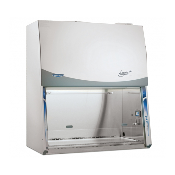
- Page 2 +® Logic Type B2 Biosafety Cabinets 2019—Present (Catalog Numbers Ending in -x1) 30348xxxx 30368xxxx...
- Page 3 + Biological Safety Cabinets and PuriCare Procedure Stations carry a five-year warranty from date of installation or six years from date of shipment from Labconco, whichever is sooner. Warranty is non- transferable and only applies to the owner (organization) of record.
-
Page 4: Table Of Contents
Unpacking the Cabinet Preparing the Cabinet for Operation Moving and Lifting the Cabinet Installing the Cabinet on an Existing Work Surface Installing the Cabinet on a Labconco Base Stand Telescoping Base Stands Manual or Electric Hydraulic Lift Base Stands Exhaust System Connections... - Page 5 5: USING THE CABINET System Reset Switch Information Center Alarm Screens 33-34 Operating the Sliding Sash Starting the Cabinet Using the Cabinet Keypad Navigating the Cabinet Menu Screens Navigating the Configuration Submenu 38-40 Activating a Startup Tone Selecting a Language Setting the Clock Setting Automatic Operation Options Navigating the Settings Submenu...
- Page 6 APPENDIX C: SPECIFICATIONS Electrical Data Motor Specifications Environmental Conditions APPENDIX D: ACCESSORIES APPENDIX E: QUICK CHART CAUTION – See Manual. When this symbol is on the unit it indicates a caution that is detailed in this manual. ATTENTION - Voir manuel. Lorsque ce symbole est allumé l'appareil, il indique une mise en garde qui est indiqué...
-
Page 7: 1: Introduction
1: Introduction ® © Congratulations on the purchase of a Labconco Purifier Biosafety Cabinet. The cabinet is designed to protect you, the product and the laboratory environment from biohazardous aerosols. It is the result of years of experience in manufacturing biohazard cabinetry, and users like you suggested many of its features to us. -
Page 8: 2: Prerequisites
2: Prerequisites Before you install the cabinet, you need to prepare the site for installation. Examine the location where you intend to install it. You must be certain that the area is level and of solid construction. In addition, a dedicated source of electrical power must be located near the installation site. -
Page 9: Location Requirements
2: Prerequisites Location Requirements The cabinet should be located away from traffic patterns, doors, fans, ventilation registers, fume hoods and any other air-handling devices that could disrupt its airflow patterns. All windows in the room should remain closed. Figure 2-1 shows the preferred location for the cabinet. -
Page 10: Exhaust Requirements
CAN BE CONFIGURED TO SIGNAL THE EXHAUST BLOWER TO TURN ON WHEN THE LOGIC+’s BLOWER IS ON. FOR FURTHER INFORMATION, CONTACT LABCONCO’S PRODUCT SERVICE DEPARTMENT. AS AN ALTERNATIVE, A REMOTE ELECTRICAL SWITCH FOR THE EXHAUST BLOWER CAN BE INSTALLED NEAR THE LOGIC+. -
Page 11: Electrical Requirements
On 100 and 115 VAC models, both internal electrical outlets are protected by a ground fault interrupter circuit (GFIC). Labconco does not recommend plugging the cabinet into a GFIC outlet. Electrical outlets in the cabinet are restricted to 5 amps (115 Volt models) or 2 amps (230 Volt models) maximum current. -
Page 12: Service Line Requirements
2: Prerequisites Service Line Requirements All utility service lines should be ¼ inch O.D., brass, copper, or stainless steel, and equipped with an easily accessible shut-off valve. If the service line pressure exceeds 40 PSI, it must be equipped with a pressure regulator to reduce the line pressure. -
Page 13: 3: Getting Started
3: Getting Started Now that the installation is properly prepared, you are ready to inspect, install, and certify the Logic+ Biosafety Cabinet. This Section covers how to: Unpack and move the cabinet Install the cabinet Connect the electrical supply source ... -
Page 14: Unpacking The Cabinet
Note: United States Interstate Commerce Commission rules require that claims be filed with the delivery carrier within fifteen (15) days of delivery. Do not return goods without the prior authorization of Labconco. Unauthorized returns will not be accepted. If the cabinet was damaged in transit, you must file a claim directly with the freight carrier. -
Page 15: Preparing The Cabinet For Operation
3: Getting Started Preparing the Cabinet for Operation Installation instructions (Labconco P/N 1056801) are attached to the sash of the cabinet. If these instructions are missing or unclear, contact Product Service at (800) 821-5525 or +1 (816) 333-8811. The following are located in a box (see Fig. -
Page 16: Installing The Cabinet On A Labconco Base Stand
3: Getting Started Installing the Cabinet on a Labconco Base Stand Labconco offers accessory base stands in a variety of configurations to suit your particular needs. If assembly of the base stand is required, the assembly instructions are packaged with the base stand. -
Page 17: Exhaust System Connections
BOARD HAS DRY CONTACTS THAT CAN BE CONFIGURED TO SIGNAL THE EXHAUST BLOWER TO TURN ON WHEN THE LOGIC BLOWER IS ON. FOR FURTHER INFORMATION, CONTACT LABCONCO’S PRODUCT SERVICE DEPARTMENT. AS AN ALTERNATIVE, A REMOTE ELECTRICAL SWITCH FOR THE EXHAUST BLOWER CAN BE INSTALLED NEAR THE LOGIC. -
Page 18: Exhaust System Requirements
3: Getting Started If your research involves the use of toxic compounds or volatile materials, contact your facility’s safety officer or Labconco to ensure that your Purifier and its exhaust system are compatible with the materials you will be working with. - Page 19 3: Getting Started 4. Push the tube into the fitting until it is properly seated. The tube will go approximately ¾ inch (19 mm) into the fitting. 5. Tighten the tube fitting nut hand tight and then, using a 7/16-inch wrench, tighten it at least ¾...
-
Page 20: Tm Cord And Cable Portal Use
3: Getting Started Using the Optional Vacu-Pass Cord & Cable Portal There must be enough clearance to pass the cord or cable between the cabinet’s exterior dress panel and any obstruction. Note: Some Vacu-Pass components and the cord or cable passing through it may become contaminated during use of the cabinet. -
Page 21: Installing The Drain Valve
3: Getting Started Installing the Drain Valve In order to prevent damage during shipping, the drain valve assembly has not been installed. If desired, the valve should be installed after the cabinet is in its final location. To install the valve assembly, follow these steps: Note: The work surface is heavy. -
Page 22: Initial Certification
*These tests are user comfort related tests and may be omitted at the user’s or certifier’s discretion. If you have any questions regarding certification agencies or help locating one, contact Labconco’s Product Service Department at (800) 821-5525 or +1 816-333- 8811. -
Page 23: 4: Performance Features & Safety Precautions
4: Performance Features and Safety Precautions All Cabinets operate using the following principles: Filtration and retention of particulates by High Efficiency Particulate Air (HEPA) filter(s) Laminar airflow Directional airflow The major components in a cabinet are: The HEPA filter(s) or optional ULPA filters ... -
Page 24: Ulpa Filters
4: Performance Features and Safety Precautions Note: The HEPA filter media is very fragile. DO NOT touch the media. If you think the media of a HEPA filter is damaged, DO NOT USE THE CABINET. Have the HEPA filter integrity tested by a certifier before using the cabinet. Note: HEPA Filters are only effective against particulate material. -
Page 25: Laminar Airflow
4: Performance Features and Safety Precautions Laminar Airflow Laminar airflow is defined as the movement of a body of air in a single direction, with a uniform velocity. In practice, the laminar downflow of air in the cabinet captures any aerosol generated in the work area of the cabinet, and directs it to the HEPA filters. -
Page 26: Directional Airflow
4: Performance Features and Safety Precautions Directional Airflow Directional airflow also plays a key role in cabinet performance. Air is drawn into the front of the cabinet at the front grille. This “curtain” of air makes it more difficult for aerosols to escape out of the work area of the cabinet and into the outside environment. -
Page 27: Motor/Blower
The motor utilizes Labconco’s exclusive Constant Airflow Profile (CAP) program to deliver a consistent volume of air, throughout the life of the cabinet. -
Page 28: Cabinet Grilles, Ductwork & Air Balance Controls
4: Performance Features and Safety Precautions Cabinet Grilles, Ductwork and Air Balance Controls The location, size, and pattern of the grilles at the front and rear of the work area affect cabinet containment and performance. Note: Do not block or obstruct the grilles of the cabinet. The internal ductwork of the cabinet conveys the air from the work area to the blower, and then from the blower to the filters. -
Page 29: Safety Precautions
HEPA filter during installation or normal operation. If you suspect that a HEPA filter has been damaged, DO NOT use the cabinet; contact a local certification agency or Labconco at (800) 821-5525 or +1 (816) 333-8811 for re- certification information. - Page 30 4: Performance Features and Safety Precautions Proper operation of the cabinet depends largely upon its location and the operator’s work habits. Consult the Installation and Normal Operation sections of this manual for further details. Avoid direct exposure of plastic or coated materials to ultraviolet (UV) radiation. Never bypass the UV safety interlock that only allows the UV light to work when the sash is closed.
-
Page 31: 5: Using The Cabinet
5: Using the Cabinet System Reset Switch The cabinet has a system reset switch for resetting its microprocessors. The switch is located on the front of the electronics module, on top of the cabinet, as shown in Figure 5-1. Ensure that the switch is in the “ON” (up) position before attempting to operate the cabinet. -
Page 32: Information Center
5: Using The Cabinet Information Center The Information Center is an LCD display located on the right side wall at eye level. When the blower is started, the “Blower Starting” screen will be displayed, as shown in Figure 5-2. After approximately 30 seconds, the display will switch to normal operation. -
Page 33: Alarm Screens
5: Using The Cabinet Alarm Screens Power Loss Alarm The cabinet has lost power. Press [OK] on the Keypad to acknowledge that a power loss occurred. Figure 5-4a Figure 5-4b Sash Height Alarm The sash is not in the proper operating height. Return sash to proper working height. - Page 34 5: Using The Cabinet Figure 5-4d Blower Failure Alarm Either the motor has failed, or the motor and display circuit board are not communicating properly. DO NOT USE THE CABINET UNTIL BLOWER FAILURE THE PROBLEM HAS BEEN CORRECTED. DETECTED CONTACT CERTIFIER Figure 5-4e Exhaust Airflow Check...
-
Page 35: Operating The Sliding Sash
5: Using The Cabinet Operating the Sliding Sash The counterbalanced, anti-racking sash mechanism requires only a few pounds of force to move the sash up or down. You can open or close the sash smoothly with one or two hands positioned on either handle. The sash position alarm and safety interlock system senses the sash position and acts appropriately. -
Page 36: Using The Cabinet Keypad
5: Using The Cabinet Using the Cabinet Keypad The keypad of the cabinet is shown in Figure 5-6. Take a moment to familiarize yourself with the buttons, their locations and functions. Also familiarize yourself with the display located on the right side wall. The display will report system functions, such as filter capacity, timer displays, alarm or error messages, as well as icons that illuminate when cabinet functions such as the light and blower are operational. -
Page 37: Navigating The Cabinet Menu Screens
5: Using The Cabinet Navigating the Cabinet Menu Screens Keypad button presses are shown as [blue with brackets]. Menu screen selections are shown as green italics. NOTE: Pressing the appropriate keypad button will override Automatic Operation mode functions (such as SmartStart and NightSmart). To access the main menu, press the [MENU] button. -
Page 38: Navigating The Configuration Submenu
5: Using The Cabinet Navigating the Configuration Submenu Figure 5-7c This submenu allows you to activate the cabinet startup tone, set the language, set the clock, and configures how the unit operates when the sash is opened or closed. Startup Tone Language Clock SmartStart / Night Smart... -
Page 39: Setting The Clock
5: Using The Cabinet Setting the Clock Figure 5-7f Select either 12 Hour (AM/PM) format or 24 Hour format. [OK/MUTE] The selected field (Hours Minutes) will flash, set the current time using [UP] and [DOWN]. Hours will flash first, once correct, use [OK/MUTE] to switch to Minutes. -
Page 40: Setting Automatic Operation Options
5: Using The Cabinet Setting Automatic Operation Options The cabinet allows you to configure it to activate functions automatically when the sash is opened or closed. Figure 5-7g The first screen gives you the option of activating the blower; if you want the cabinet blower to start every time you raise the sash, select Blower On, and then... -
Page 41: Navigating The Settings Submenu
5: Using The Cabinet Navigating the Settings Submenu Figure 5-7l This submenu allows you to select: Units of Measure, System Lock, Data Output, or Parameters. Units of Measure System Lock Data Output UV Parameters Selecting the Units of Measure Figure 5-7m If your cabinet is equipped with an airflow sensor, the units of measure can be set for FT/MIN... -
Page 42: Navigating Uv Parameters
5: Using The Cabinet Navigating UV Parameters For models equipped with the optional UV light, the cabinet has an integral UV light maintenance system. It allows you to monitor how many hours the lamp has been on, to reset the UV lamp hourmeter, and to define how many hours you want the UV lamp to operate before receiving a reminder to replace it. -
Page 43: Timer Operation
5: Using The Cabinet Timer Operation The timer button allows activation of an interval (countdown) or elapsed (stopwatch) timer. The timers cannot be operated simultaneously. To access the timer menu, press [Timer] anytime during normal operation (from the Home Screen). The main timer menu is displayed (Fig. 5-8a). Select Interval Stopwatch Timer, then [OK/MUTE]. -
Page 44: If An Airflow Alert Activates
5: Using The Cabinet If An Airflow Alert Activates Figure 5-9 The most common causes of an Airflow Alert are: Blockage of the inlet grilles or exhaust outlet Removal of the work surface or grille during operation Resetting the Airflow Alert System The Airflow Alert automatically resets to normal operation once the motor speed has stabilized. - Page 45 5: Using The Cabinet Wash hands and arms thoroughly with germicidal soap Wear appropriate personnel protective equipment (PPE) Wipe-Down Raise the sash to its full open position (approximately 21.75 inches or 552 mm). Mute the alarm by pressing [OK/MUTE] ...
- Page 46 5: Using The Cabinet Final Purging Upon completion of work, the cabinet should be allowed to operate for two to three minutes undisturbed, to purge airborne contaminants from the work area Unloading Materials and Equipment Objects in contact with contaminated material should be surface decontaminated before removal from the cabinet ...
-
Page 47: 6: Maintaining The Cabinet
+ Cabinets Second Generation. This manual is available from Labconco’s Logic ® website labconco.com. A complete certifier service kit is available to qualified certifiers from Labconco. Call Labconco’s Product Service Department at (800) 821-5525 or +1 (816) 333-8811. Do NOT contact blower wheel while still in motion. -
Page 48: Suggested Maintenance Schedule
6: Maintaining The Cabinet Suggested Maintenance Schedule Maintenance Frequency Activity Weekly Monthly Annually Disinfect interior surfaces (with suitable chemical disinfectant) Wipe down interior surfaces after contact time elapsed with 70% alcohol solution ... -
Page 49: Service Operations
6: Maintaining The Cabinet Service Operations Work Surface Removal: Note: The work surface must be thoroughly decontaminated before removing it from the cabinet. 1. Lift the front edge of the work surface straight up by grasping the knob handles at either front corner. 2. -
Page 50: Towel Catch Removal
6: Maintaining The Cabinet Towel Catch Removal: Although not normally required, the towel catch can be removed for cleaning, inspection, etc. Note: The work surface of the cabinet and the towel catch must be thoroughly decontaminated before removing either. 1. Remove the work surface as described above. 2. -
Page 51: Front Panel Removal & Installation
6: Maintaining The Cabinet Front Panel Removal and Installation: Figure 6-3 Dress Panel 1. Locate and remove the two Phillips screws that secure the front panel as shown. They are located on the bottom corners of the dress panel. 2. Swing the bottom of the dress panel out to clear the LED lamps and then lift the dress panel straight up and away... -
Page 52: Changing The Led Lamps
6: Maintaining The Cabinet Changing the LED Lamps: 1. Unplug the cabinet or turn off the System Reset Switch located on the top of the cabinet. 2. Remove the front dress panel as noted in Figure 6-3. 3. Locate the Left End Cap that aligns both LED lamps (Fig. 6-5a), remove the Left End Cap by pulling it away from the lamp ends. -
Page 53: Changing The Optional Uv Lamp
6: Maintaining The Cabinet 5. Pull each LED Lamp straight toward you to release the lamp from the two Spring Clips holding it in place (Fig. 6-5b). Note the rotational position of the old LED lamps (there is a dead band stripe that will need to be oriented the same when reinstalling the new LED Lamps). -
Page 54: Resetting A Circuit Breaker
6: Maintaining The Cabinet The UV lamp and the work area of the cabinet must be thoroughly decontaminated before removing the lamp. 1. Start the cabinet’s blower and let it operate for 5 minutes. 2. Raise the sash to its full open position. 3. -
Page 55: 7: Troubleshooting
7: Troubleshooting Refer to the following table if the cabinet fails to operate properly. If the suggested corrective actions do not solve the problem, contact Labconco for additional assistance. PROBLEM CAUSE CORRECTIVE ACTION Cabinet blower and Unit not plugged Plug the cabinet into appropriate... - Page 56 7: Troubleshooting PROBLEM CAUSE CORRECTIVE ACTION Open sash – Lights will not work Light not working Sash is closed with the sash closed Lamp(s) are Replace defective lamp(s) defective Lamp wiring is Inspect lamp wiring disconnected Keypad Run keypad diagnostics and check disconnected or connections defective...
- Page 57 7: Troubleshooting PROBLEM CAUSE CORRECTIVE ACTION Airflow Alert goes HEPA filter loading The gauge reading steadily off and/or there is decreases as the cabinet is used. a slight decrease A very slow decrease (over months) in filter life is normal remaining gauge Blockage of the Check all return air slots and grilles...
- Page 58 7: Troubleshooting PROBLEM CAUSE CORRECTIVE ACTION Contamination of Improper technique See Working In the Cabinet section work in the or procedure for the at the end of Section 5 in this cabinet cabinet manual Restriction of the Ensure that all return air slots, return air slots or grilles and the exhaust outlet are grille –...
-
Page 59: Appendix A: Components
Appendix A: Components Illustration A-1 indicates the location of the following service parts, and replacement accessory parts: Cabinet Replacement Parts Quantity Item Required Catalog Number Description 3850500 Pre-Filter for 4 Foot B2 Model 3850501 Pre-Filter for 6 Foot B2 Model 3438501 Exhaust HEPA Filter 4 Foot B2 Model 3438503... -
Page 60: Appendix B: Dimensions
Appendix B: Dimensions All dimensions are shown in inches. Exhaust duct stub sized for 10 inch outside diameter duct connection Power Cord Connection Width 54.3 48.5 17.2 78.3 72.5 28.9 Power Cord Connection 72.6 61.7 29.2 25.7 21.7 Max Loading 17.6 31.2... -
Page 61: Appendix C: Specifications
Appendix C: Specifications Electrical Data Typical Startup - Electrical Circuit Catalog Number Operating Current Requirements 3034xxx01 115 V, 60 Hz, 12 A 3034xxx21 100 V, 50/60 Hz, 12 A 3034xxx-11, 31, 41, 51, 61, 71 1.5 A 230 V, 50/60 Hz, 6 A 3036xxx01 115 V, 60 Hz, 12 A 3036xxx21... -
Page 62: Environmental Conditions
Appendix C: Specifications Environmental Conditions Indoor use only Ambient temperature range: 41° to 104°F (5° to 40°C) Maximum relative humidity: 80% for temperatures up to 88°F (31°C), decreasing linearly to 50% relative humidity at 104°F (40°C) Main supply voltage fluctuations not to exceed ±10% of the nominal voltage ... -
Page 63: Appendix D: Accessories
Appendix D: Accessories Labconco offers a full line of accessories to enhance your cabinet’s operation and usability. For a complete list visit labconco.com. -
Page 64: Appendix E: Quick Chart
2. These values equal the Concurrent Balance Values (CVB) published by National Sanitation Foundation International (NSF). 3. Each motor must be programmed by Labconco for the appropriate width cabinet. 4. THIS PRODUCT USES DIRECT DRIVE T8 LED LAMPS INSTEAD OF FLUORESCENT LAMPS.
Need help?
Do you have a question about the Logic+ 30348 Series and is the answer not in the manual?
Questions and answers