Labconco Purifier Logic+ 30231 Series User Manual
Biological safety cabinets
Hide thumbs
Also See for Purifier Logic+ 30231 Series:
- Technical manual and specifications (174 pages)
Table of Contents
Advertisement
Quick Links
TYPE
A2
User's Manual
Purifier
Biological Safety Cabinets
30231 Series
30241 Series
30251 Series
30261 Series
To receive important product updates,
complete your product registration card
online at register.labconco.com
Please read the User's Manual before operating the equipment.
®
Models
30238 Series
30248 Series
30258 Series
30268 Series
Labconco Corporation
8811 Prospect Avenue
Kansas City, MO 64132-2696
800-821-5525, 816-333-8811
FAX 816-363-0130
E-MAIL
HOME PAGE www.labconco.com
Original instructions
labconco@labconco.com
Advertisement
Table of Contents

Subscribe to Our Youtube Channel
Related Manuals for Labconco Purifier Logic+ 30231 Series


Summary of Contents for Labconco Purifier Logic+ 30231 Series
- Page 1 30241 Series 30248 Series 30251 Series 30258 Series 30261 Series 30268 Series To receive important product updates, complete your product registration card online at register.labconco.com Labconco Corporation TYPE 8811 Prospect Avenue Kansas City, MO 64132-2696 800-821-5525, 816-333-8811 FAX 816-363-0130 E-MAIL labconco@labconco.com...
- Page 2 Original instructions This page is intentionally blank.
- Page 3 This limited warranty covers parts and labor, but not transportation and insurance charges. In the event of a warranty claim, contact Labconco Corporation or the dealer who sold you the product. If the cause is determined to be a manufacturing fault, the dealer or Labconco Corporation will repair or replace all defective parts to restore the unit to operation.
-
Page 4: Table Of Contents
Preparing the Biosafety Cabinet for Operation Moving and Lifting the Biosafety Cabinet Installing the Biosafety Cabinet on an Existing Work Surface Installing the Biosafety Cabinet on a Labconco Base Stand Telescoping Base Stands Manual or Electric Hydraulic Lift Base Stands... - Page 5 Original instructions System Reset Switch Information Center Alarm Screens Operating the Sliding Sash Starting the Biosafety Cabinet The Logic+ Touchpad Navigating the Logic+ Menu Screens Navigating the MyLogic Menu Screens 29-31 Setting the Clock Configuring the Logic+ 30-31 Navigating the Settings Screens 31-34 Display Options 31-32...
- Page 6 Original instructions APPENDIX C: SPECIFICATIONS Electrical Data Motor Specifications Environmental Conditions APPENDIX D: ACCESSORIES APPENDIX E: QUICK CHART CAUTION – See Manual. When this symbol is on the unit it indicates a caution that is detailed in this manual. ATTENTION - Voir manuel. Lorsque ce symbole est allumé l'appareil, il indique une mise en garde qui est indiqué...
-
Page 7: Chapter 1: Introduction
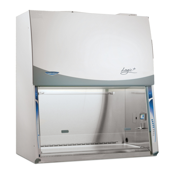
Original instructions ® © Congratulations on the purchase of a Labconco Purifier Logic+ Biosafety Cabinet. The biosafety cabinet is designed to protect you, the product and the laboratory environment from biohazardous aerosols. The Logic+ is the result of years of experience in manufacturing biohazard cabinetry, and users like you suggested many of its features to us. -
Page 8: Chapter 2: Prerequisites
Original instructions Before you install the Logic+, you need to prepare the site for installation. Examine the location where you intend to install the cabinet. You must be certain that the area is level and of solid construction. In addition, a dedicated source of electrical power must be located near the installation site. -
Page 9: Location Requirements
Original instructions Chapter 2: Prerequisites Location Requirements Note: The biosafety cabinet should be located away from traffic patterns, doors, fans, ventilation registers, fume hoods and any other air-handling devices that could disrupt its airflow patterns. All windows in the room should remain closed. -
Page 10: Exhaust Requirements
Note: On 100 and 115 VAC models, both electrical outlets are protected by a ground fault interrupter circuit (GFIC). Labconco does not recommend plugging the biosafety cabinet into a GFIC outlet. Product Service 1-800-522-7658... -
Page 11: Service Line Requirements
Original instructions Chapter 2: Prerequisites Electrical outlets in the cabinet are restricted to 5 amps maximum current. Prises électriques dans l'armoire sont limitées à 5 courant maximum ampères. Do not use any detachable power cord that is not adequately rated for the unit. Ne pas utliser un fil électrique amovible qui n’est pas du tension nominale de l’appareil. - Page 12 Original instructions Now that the installation is properly prepared, you are ready to inspect, install, and certify the Logic+ biosafety cabinet. This chapter covers how to: • Unpack and move the biosafety cabinet. • Install the cabinet. • Connect the electrical supply source. •...
-
Page 13: Chapter 3: Getting Started
Unauthorized returns will not be accepted. If the cabinet was damaged in transit, you must file a claim directly with the freight carrier. Labconco Corporation and its dealers are not responsible for shipping damages. Do not discard the carton or packing material for the biosafety cabinet until all of the components have been checked, installed and tested. -
Page 14: Moving And Lifting The Biosafety Cabinet
Installing the Cabinet on a Labconco Base Stand Labconco offers accessory Base Stands in a variety of configurations to suit your particular needs. Stands can be ordered with adjustable telescoping legs or with a manually or electrically adjustable hydraulic lift. -
Page 15: Telescoping Base Stands
Original instructions Chapter 3: Getting Started Telescoping Base Stands These stands are included with some Logic+ models, or are available separately. The base stands for each width cabinet are listed in Table 3-1 below. An optional caster wheel kit is available (part # 3730500). Table 3-1 Width Base Stand w/Feet Model #... -
Page 16: Connecting The Biosafety Cabinet To Utility Service Lines
Original instructions Chapter 3: Getting Started Connecting the Biosafety Cabinet to Utility Service Lines Note: Some models have a solenoid valve connected to the service valve on the right side, rear position. The solenoid prevents gas from flowing to the service valve when the unit blower is off. -
Page 17: Optional Ventus Tm Exhaust System Connections
Accessories. Note: If the research involves the use of toxic compounds or volatile materials, contact the facility’s safety officer or Labconco to ensure that the biosafety cabinet and its exhaust system are compatible with the materials you will be working with. -
Page 18: Optional Vacu-Pass Tm Cord And Cable Portal Use
Original instructions Chapter 3: Getting Started Optional Vacu-Pass Cord & Cable Portal Use Note: There must be enough clearance to pass the cord or cable between the Logic+’s exterior dress panel and any obstruction. Note: Some Vacu-Pass components and the cord or cable passing through it may become contaminated during use of the cabinet. -
Page 19: Drain Valve Installation
Original instructions Chapter 3: Getting Started Drain Valve Installation In order to prevent damage during shipping, the drain valve assembly has not been installed. If desired, the valve should be installed after the cabinet is in its final location. To install the valve assembly, follow these steps: Note: The work surface is heavy. -
Page 20: Initial Certification
*These tests are user comfort related tests and may be omitted at the user’s or certifier’s discretion. If you have any questions regarding certification agencies or need assistance in locating one, contact Labconco’s Product Service Department at 1-800- 522-7658 or 816-333-8811. Product Service 1-800-522-7658... -
Page 21: Hepa Filters
Original instructions All Purifier Logic+ Biosafety Cabinets operate using the following principles: • Filtration and retention of particulates by High Efficiency Particulate Air (HEPA) filter(s) • Laminar airflow • Directional airflow The major components in a biosafety cabinet are: • The HEPA filter(s) or optional ULPA filters •... -
Page 22: Chapter 4: Performance Features And Safety Precautions
Original instructions Chapter 4: Performance Features and Safety Precautions Note: The HEPA filter media is very fragile. DO NOT touch the media. If you think the media of a HEPA filter is damaged, DO NOT USE THE CABINET. Have the HEPA filter integrity tested by a certifier before using the cabinet. -
Page 23: Laminar Airflow
Original instructions Chapter 4: Performance Features and Safety Precautions Laminar Airflow Laminar airflow is defined as the movement of a body of air in a single direction, with a uniform velocity. In practice, the laminar downflow of air in the cabinet captures any aerosol generated in the work area of the cabinet, and directs it to the HEPA filters. -
Page 24: Directional Airflow
Original instructions Chapter 4: Performance Features and Safety Precautions Directional Airflow Directional airflow also plays a key role in biosafety cabinet performance. Air is drawn into the front of the cabinet at the front grille. This “curtain” of air makes it more difficult for aerosols to escape out of the work area of the cabinet and into the outside environment. -
Page 25: Motor/Blower
The motor utilizes Labconco’s exclusive Constant Airflow Profile (CAP) program to deliver a consistent volume of air, throughout the life of the cabinet. -
Page 26: Cabinet Air Intakes (Grilles), Ductwork & Air Balance Controls
Original instructions Chapter 4: Performance Features and Safety Precautions Cabinet Air Intakes (Grilles), Ductwork and Air Balance Controls The location, size, and pattern of the grilles at the front and rear of the work area affect cabinet containment and performance. Note: Do not block or obstruct the grilles of the biosafety cabinet. -
Page 27: Safety Precautions
HEPA filter during installation or normal operation. If you suspect that a HEPA filter has been damaged, DO NOT use the cabinet; contact a local certification agency or Labconco at 800-821-5525 or 816-333- 8811 for re-certification information. The HEPA filters in the biosafety cabinet will gradually accumulate airborne particulate matter from the room and from work performed in the cabinet. - Page 28 Original instructions Chapter 4: Performance Features and Safety Precautions Proper operation of the cabinet depends largely upon its location and the operator’s work habits. Consult the Installation and Normal Operation sections of this manual for further details. Avoid direct exposure of plastic or coated materials to ultraviolet (UV) radiation.
-
Page 29: Chapter 5: Using The Cabinet
Original instructions System Reset Switch The biosafety cabinet has a system reset switch for resetting its microprocessors. The switch is located on the front of the electronics module, on top of the cabinet, as shown in Figure 5-1. Ensure that the switch is in the “ON”... -
Page 30: Information Center
Original instructions Chapter 5: Using The Cabinet Information Center The Information Center is an LCD display located on the right side wall at eye level. When the blower is started, the words “please wait” will be displayed, as shown in Figure 5-2. After approximately 90 seconds, the display will switch to normal operation. -
Page 31: Alarm Screens
Original instructions Chapter 5: Using The Cabinet Alarm Screens Figure 5-4a Sash is too high The sash is open too far for safe operation. Figure 5-4b Airflow Alert The airflow patterns in the cabinet have changed, resulting in a sudden change in the motor speed. This is most likely due to a blockage of the grille or the exhaust filter outlet. -
Page 32: Operating The Sliding Sash
Original instructions Chapter 5: Using The Cabinet Operating the Sliding Sash The counterbalanced, anti-racking sash mechanism requires only a few pounds of force to move the sash up or down. You can open or close the sash smoothly with one or two hands positioned on either handle. The sash position alarm and safety interlock system senses the sash position and acts appropriately. -
Page 33: The Logic+ Touchpad
Original instructions Chapter 5: Using The Cabinet The Logic+ Touchpad The touchpad of the Logic+ is shown in Figure 5-6. Take a moment to get familiar with the buttons, their locations and functions. Also familiarize yourself with the display located on the right side wall. The display will report system functions, such as filter capacity, timer displays, alarm or error messages, as well as icons that illuminate when cabinet functions such as UV light and blower are operational. -
Page 34: Navigating The Logic+ Menu Screens
Original instructions Chapter 5: Using The Cabinet Navigating the Logic+ Menu Screens MyLogic allows you to use the Smart-Start or Night-Smart features that activate functions automatically when the sash is opened or closed. If equipped, the UV lamp can be programmed to operate for a given time interval when the sash is closed, before it shuts off. -
Page 35: Navigating The Mylogic
Original instructions Chapter 5: Using The Cabinet Navigating the MyLogic Menu Screens The MyLogic screens will allow you to set the cabinet’s clock, and to personalize its operation. Please note all MyLogic screens have a blue background. Setting the Clock ▲... -
Page 36: Configuring The Logic
Original instructions Chapter 5: Using The Cabinet Configuring the Logic+ In the first MyLogic screen, use the ▲ ▼ buttons on the touchpad to highlight configure my Logic for use -it will turn white when selected. Press to enter the first configuration screen: The first screen gives you the option of activating the Smart-Start option for the blower;... -
Page 37: Navigating The Settings Screens
Original instructions Chapter 5: Using The Cabinet If you choose to use Night-Smart option for the UV lamp, this screen allows you to control the time the UV lamp will remain on after the sash is closed. Use the ▲ ▼... -
Page 38: Startup Tone
Original instructions Chapter 5: Using The Cabinet Startup tone Using the ▲ ▼ buttons on the touchpad, highlight the Startup Tone option-it will turn white when selected, and then press OK. Using the ▲ ▼ buttons on the touchpad, highlight either Turned on Turned off... -
Page 39: Uv Settings
Original instructions Chapter 5: Using The Cabinet UV Settings For models equipped with the optional UV light the Logic+ has an integral UV light maintenance system. It allows you to define how many hours you want the UV lamp to operate before receiving a reminder to replace it, a way to monitor how many hours the lamp has been on, and the means to reset the UV lamp hourmeter. -
Page 40: Change Uv Lamp Life
Service Menu screens that can alter the performance of the Logic+ are password protected. If you have any questions about these screens, contact Labconco’s Product Service Department at 1-800-821-5525 or www.labconco.com for assistance. -
Page 41: Timer Operation
Original instructions Chapter 5: Using The Cabinet Timer Operation NOTE: The timer button allows activation of an interval (countdown) or stopwatch (elapsed) timer. The timers cannot be operated simultaneously. To access the main timer menu, press the Timer button anytime during normal operation. -
Page 42: Working In The Biosafety Cabinet
Original instructions Chapter 5: Using The Cabinet Working In the Biosafety Cabinet Note: A more thorough review of using the BSC can be found in: Biosafety in Microbiological and Biomedical Laboratories (BMBL), Published by the Centers for Disease Control and Prevention (www.cdc.gov/biosafety/publications). - Page 43 Original instructions Chapter 5: Using The Cabinet Loading Materials and Equipment • Only load the materials required for the procedure. Do not overload the cabinet. • Do not obstruct the front, side, or rear return air grilles. • Large objects should not be placed close together. •...
- Page 44 Original instructions Chapter 5: Using The Cabinet Unloading Materials and Equipment • Objects in contact with contaminated material should be surface decontaminated before removal from the cabinet. • All open trays or containers should be covered before being removed from the cabinet. Wipe-Down •...
-
Page 45: Routine Maintenance Schedule
• Using an appropriate glass cleaner, or LabSolutions Glass & Surface Wipes, Labconco part # 1570000; clean the sash and the surface of the UV lamp, if so equipped. • Operate the cabinet blower, noting the percent filter life remaining in an operational log. -
Page 46: Chapter 6: Maintaining The Cabinet
Original instructions Chapter 6: Maintaining The Cabinet particularly the front and top of the cabinet, to remove any accumulated dust. • Disinfect and lift the work surface. Surface disinfect the area beneath the work surface with a suitable disinfectant, or 70% ethanol, and allow to dry. -
Page 47: Towel Catch Removal
Original instructions Chapter 6: Maintaining The Cabinet 4. Reinstall the grille by reversing the above sequence, ensuring that the grille properly engages the bottom edge of the cabinet. Figure 6-1 Towel Catch Removal: Although not normally required, the towel catch can be removed for cleaning, inspection, etc. -
Page 48: Front Panel Removal & Installation
Original instructions Chapter 6: Maintaining The Cabinet Figure 6-2 Sampling/Decontamination Tube Towel Catch Retaining Spring Towel Catch Note: Upper and lower towel catch flanges point to the front of the cabinet, and the bottom of the towel catch rests against the back wall. -
Page 49: Changing The Fluorescent Lamps
Original instructions Chapter 6: Maintaining The Cabinet Figure 6-4 1. To reinstall the panel, reverse these steps, ensuring that the plastic pin in the top corners of the dress panel properly engage the corner posts. Changing the Fluorescent Lamps: 1. Unplug the cabinet or turn off the System Reset Switch located on the top of the cabinet. -
Page 50: Resetting A Circuit Breaker
Original instructions Chapter 6: Maintaining The Cabinet 4. Unplug the cabinet or turn off the System Reset Switch, located on the top of the cabinet. 5. Remove the UV lamp by rotating it 90 degrees and lifting it straight up and out of its sockets. -
Page 51: Chapter 7: Troubleshooting
Original instructions Refer to the following table if the biosafety cabinet fails to operate properly. If the suggested corrective actions do not solve the problem, contact Labconco for additional assistance. PROBLEM CAUSE CORRECTIVE ACTION Cabinet blower and Unit not plugged into... - Page 52 Original instructions Chapter 7: Troubleshooting PROBLEM CAUSE CORRECTIVE ACTION Fluorescent light not Sash is closed Open sash – Fluorescent lights will not working work with the sash closed. Lamp(s) are defective Replace defective lamp(s) Lamp wiring is Inspect lamp wiring. disconnected Defective lamp Replace lamp ballasts.
- Page 53 Original instructions Chapter 7: Troubleshooting PROBLEM CAUSE CORRECTIVE ACTION Airflow Alert goes HEPA filter loading The gauge reading steadily decreases as off and/or there is a the cabinet is used. slight decrease in filter life remaining gauge Blockage of the Check all return air slots and grilles to return air slots or ensure that they are not blocked or...
-
Page 54: Appendix A: Components
Original instructions Illustration A-1 indicates the location of the following service parts, and replacement accessory parts: Biosafety Cabinet Replacement Parts Item Quantity Part No. Description 3838500 Exhaust HEPA Filter 3-ft 3838501 Exhaust HEPA Filter 4-ft 3838502 Exhaust HEPA Filter 5-ft 3838503 Exhaust HEPA Filter 6-ft 3838400... - Page 55 Original instructions Appendix A: Components Product Service 1-800-522-7658...
-
Page 56: Appendix B: Dimensions
Original instructions All dimensions in inches. Exhaust duct connection sized for 10 inch (254 mm) outside diameter duct. Power Cord Connection 9.06 Width “A” “B” “C” 42.3 36.5 13.6 54.3 48.5 19.9 66.3 60.5 26.9 78.3 72.5 32.9 Power Cord Connection 65.4 61.7... - Page 57 Original instructions Electrical Data Model # Requirements 3023xxx0x 115 VAC, 60 Hz, 12 Amps 3023xxx1x 100 VAC, 50/60 Hz, 12 Amps 3023xxx-20, 30, 40, 50, 60, 70 230 VAC, 50/60 Hz, 6 Amps 3024xxx0x 115 VAC, 60 Hz, 12 Amps 3024xxx1x 100 VAC, 50/60 Hz, 12 Amps 3024xxx-20, 30, 40, 50, 60, 70, 80...
- Page 58 Original instructions Appendix C: Specifications Environmental Conditions • Indoor use only. • Ambient temperature range: 41° to 104°F (5° to 40°C). • Maximum relative humidity: 80% for temperatures up to 88°F (31°C), decreasing linearly to 50% relative humidity at 104°F (40°C). •...
- Page 59 Original instructions Labconco offers a full line of accessories to enhance your Logic+’s operation and usability. For a complete list of these accessories, please consult our website at www.labconco.com Product Service 1-800-522-7658...
- Page 60 The next 5 digits are the sequence of production, and the letter following the serial number is the revision level of the cabinet. Each motor must be programmed by Labconco for the appropriate width cabinet. Product Service 1-800-522-7658...
Need help?
Do you have a question about the Purifier Logic+ 30231 Series and is the answer not in the manual?
Questions and answers