Table of Contents
Advertisement
Quick Links
ECAT-2610 EtherCAT to Modbus
RTU Gateway
User Manual
English Ver. 1.0, Dec. 2017
WARRANTY
All products manufactured by ICP DAS are warranted against
defective materials for a period of one year from the date of
delivery to the original purchaser.
WARNING
ICP DAS assumes no liability for damages consequent to the use
of this product. ICP DAS reserves the right to change this manual
at any time without notice. The information furnished by ICP
DAS is believed to be accurate and reliable. However, no
responsibility is assumed by ICP DAS for its use, nor for any
infringements of patents or other rights of third parties resulting
from its use.
COPYRIGHT
Copyright © 2017 by ICP DAS. All rights are reserved.
TRADEMARK
Names are used for identification only and may be registered
trademarks of their respective companies.
CONTACT US
If you have any questions, please feel free to contact us via email at:
service@icpdas.com, service.icpdas@gmail.com
Advertisement
Table of Contents

Related Manuals for ICPDAS ECAT-2610


Summary of Contents for ICPDAS ECAT-2610
- Page 1 ECAT-2610 EtherCAT to Modbus RTU Gateway User Manual English Ver. 1.0, Dec. 2017 WARRANTY All products manufactured by ICP DAS are warranted against defective materials for a period of one year from the date of delivery to the original purchaser.
-
Page 2: Table Of Contents
EtherCAT to Modbus RTU Gateway TABLE OF CONTENTS PACKAGE LIST ................................4 MORE INFORMATION ..............................4 INTRODUCTION ..............................5 ................................6 EATURES ..............................6 LOCK IAGRAM HARDWARE INFORMATION ..........................7 ................................. 7 PPEARANCE ..............................10 PECIFICATION ..............................11 SSIGNMENTS EtherCAT Interface ..............................11 COM1 (Console Port) .............................. - Page 3 TANDARD BJECT ..............................68 PECIFIC BJECTS Input Buffer ................................68 Output Buffer ................................68 APPLICATIONS ..............................69 ECAT F ICPDAS ............................69 AMILY OF .............................. 72 ELCOME APPENDIX ................................. 75 A1. H RTU C DCON U ? ..................75 OW DO...
-
Page 4: Package List
Software CD x 1 CA-0915 Cable x 1 ECAT-2610 x 1 If any of these items is missing or damaged, please contact your local distributor for more information. Keep the shipping materials and overall package in case you want to NOTE ship the module back in the future. -
Page 5: Introduction
Just connect, configure and it’s finished. The ECAT-2610 Communicator is a proven and trusted protocol converter gateway that connects non-networked industrial devices and equipment to EtherCAT. The gateway performs an intelligent protocol conversion and presents the serial data to the Master PLC/Controller as easily processed I/O data. -
Page 6: Features
Supports maximum Baud Rate 115200 bps. 1.2 Block Diagram The block diagram of the ECAT-2610 module is given as follows: Figure 1-2 Block Diagram of ECAT-2610 Copyright © 2017 ICP DAS CO., Ltd. All Rights Reserved. - 6 -... -
Page 7: Hardware Information
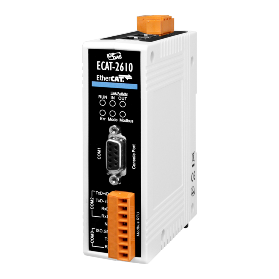
EtherCAT to Modbus RTU Gateway 2. Hardware Information 2.1 Appearance The front panel and top panel of the ECAT-2610 module contain the Modbus COM Port, PC COM port, LEDs, Ethernet Port and power connector. Top Panel 1. DC Power Input Connector Figure 2-1 2. - Page 8 Indicators 4. ECAT-2610 Status Indicators 5. COM1 (Console Port) 6. COM2/COM3 (Modbus RTU) Figure 2-2 Front panel of ECAT-2610 EtherCAT bus Status Indicators Notation Color States Description The device is in state INIT Blinking The device is in state PRE-OPERARIONAL...
- Page 9 EtherCAT to Modbus RTU Gateway ECAT-2610 Status Indicators Notation Color States Description Normal Blinking Error Flashing for 0.3 sec DC enable Flashing for 1 sec Normal Mode Green No configuration file or configuration file Flashing for 2 sec error Flashing for 4 sec...
-
Page 10: Specification
EtherCAT to Modbus RTU Gateway 2.2 Specification Model ECAT-2610 Protocol EtherCAT Communication RJ-45 x 1 Distance between Stations: Max. 100 m (100BASE-TX) RJ-45 Port Data Transfer Medium: Ethernet/EtherCAT Cable (Min.CAT 5e) The RS-232, RS-422 and RS-485 cannot be used simultaneously... -
Page 11: Pin Assignments
EtherCAT to Modbus RTU Gateway 2.3 Pin Assignments EtherCAT Interface Pin Assignment F.G. GND(-) PWR(+) COM1 (Console Port) Terminal Terminal Pin Assignment Pin Assignment COM2/COM3 (Modbus RTU) Pin Assignment Terminal No. TxD+/D+ TxD-/D- NOTE COM2 RxD+ The RS-232, RS-422 and RS-485 cannot be used RxD- simultaneously. -
Page 12: Wiring Connections
EtherCAT to Modbus RTU Gateway 2.4 Wiring Connections 3-wire RS-232 Wiring 4-wire RS-422 Wiring NOTE 1. Usually, you have to connect all signal grounds of RS-422/485 devices together to reduce common-mode voltage between devices. 2. Twisted-pair cable must be used for the DATA+/- wires. -
Page 13: Init/Normal Operating Mode
2. Short the TxD and RxD pins on the COM3 to Init mode. 3. Run the 7188ECAT.exe, and power on the ECAT-2610 module to verify that enter the init mode. 4. Disconnect the TxD and RxD pins on the COM3 to normal mode. -
Page 14: Dimensions
EtherCAT to Modbus RTU Gateway 2.6 Dimensions The following diagrams provide the dimensions of the ECAT-2610 module and can be used as a reference when defining the specifications for any custom enclosures. All dimensions are in millimeters. Front Rear Left Side... -
Page 15: Getting Started
This chapter provides detailed information about the Self-test process, which is used to confirm that the ECAT-2610 is operating correctly. 3.1 Factory Default Settings The following is an overview of the factory default settings for ECAT-2610 module: Item Default Settings... -
Page 16: Connecting The Power And The Host Pc
3.2 Connecting the Power and the Host PC Step 1 Connect both the IN port of ECAT-2610 module and RJ-45 Ethernet port of Host PC. Ensure that the network settings on the Host PC have been correctly configured and are functioning normally. - Page 17 EtherCAT to Modbus RTU Gateway Step 3 Verify that LEDs indicator on the ECAT-2610 module is given as follows: RUN = Red IN = Green Flashing Mode = Green Flashing Figure 3-2.2 Copyright © 2017 ICP DAS CO., Ltd. All Rights Reserved.
-
Page 18: Configuration And Operation
This can be downloaded from the ICP DAS website (http://ftp.icpdas.com/pub/cd/fieldbus_cd/ethercat/slave/ecat-2000/software/) and installed according to the installation instructions. Step 1 Install the ESI file Copy the “ICPDAS ECAT-2610.xml” file to the Master Tools installation folder, as indicated in the table below. Software Default Path Beckhoff EtherCAT Configuration C:\EtherCAT Configurator\EtherCAT Beckhoff TwinCAT 3.X... - Page 19 In000 is 0x80 (status_low) and In001 is 0xC0 (status_hi). Figure 3-2.4 NOTE For detailed information about the status_low and status_hi of ECAT-2610, refer to Section 3.3.1 “Module Status and Error Mode”. Copyright © 2017 ICP DAS CO., Ltd. All Rights Reserved.
-
Page 20: Module Status And Error Mode
ECAT-2610 module in the default configuration file. Under this command, once power is supplied to the ECAT-2610 module, the ECAT-2610 module will read and check the configuration file from EEPROM. If there is any error detected that ECAT-2610 module will enter the error mode, the details as below: The Err LED indicator will illuminate as follows: ... - Page 21 EtherCAT to Modbus RTU Gateway Check results of the Modbus command are given in status_hi as follows: InTxPDO[01] = status_hi = 0xC0 (normal settings), the status_hi is defined as follows: Cmd Fun Cmd Length CmdNum Error Error Error Command Function Error, refer to Chapter 5 “Modbus Information”...
-
Page 22: Modbus Rtu Device Setup
EtherCAT to Modbus RTU Gateway 4. Modbus RTU Device Setup Before beginning the “Modbus RTU device Setup” process, ensure that your ECAT-2610 module is operating correctly, refer to Chpater 3 “Getting Started” for more NOTE detailed information. Here, the M-7050D module is used as an example. For other Modbus RTU device or third party Modbus RTU device, refer to the specific Quick Start Guide or User Manual for that Modbus RTU device. -
Page 23: Configure The Modbus Rtu Device
For ICP DAS Modbus RTU slave device, the DCON Utility Pro is free download and installation, it can be obtained from the ICP DAS web site at: http://ftp.icpdas.com/pub/cd/8000cd/napdos/driver/dcon_utility/ to search modules out and configure the searched devices. Copyright © 2017 ICP DAS CO., Ltd. All Rights Reserved. - Page 24 EtherCAT to Modbus RTU Gateway Step 3 Search Module Click “COM Port” button to select COM Port (e.g., COM1) depends on Host PC COM Port that connects to M-7050D and click “OK” button. Figure 4-1.2 Click “Start Search” button to search Modbus RTU device. Figure 4-1.3 ...
- Page 25 EtherCAT to Modbus RTU Gateway Step 4 Configuring the Net ID , Baud Rate and Data Format Click the module name to open the configuration dialog box. Set the Address (Net ID), Baud Rate and Data Format for Modbus RTU device. ...
-
Page 26: Configuring And Uploading
EtherCAT to Modbus RTU Gateway 4.2 Configuring and Uploading Step 1 Connect the Download Cable to the Host PC. Connect the COM1 of ECAT-2610 to COM Port of Host PC using the CA-0915 download cable. CA-0915 Cable Step 2 Download the ECAT-2610_Utl_xxxxxx.zip. - Page 27 EtherCAT to Modbus RTU Gateway Step 3 Execute the ECAT-2610 Configuration Tool.exe. Double-click the “ECAT-2610 Configuration Tool.exe” to open configuration toolkit. Figure 4-2.2 Copyright © 2017 ICP DAS CO., Ltd. All Rights Reserved. - 27 -...
- Page 28 Modify COM Port number, Baud Rate and Data Format. 1. Modify COM Port number in “COM” field, depend on your Host PC COM Port (e.g., COM4) that connect to ECAT-2610. 2. Select the appropriate Baud Rate and Data Format settings from the relevant drop down options depending on the Modbus RTU device (e.g., M-7050D).
- Page 29 Figure 4-2.5 Step 6 Click the “CONNECT”to connect the ECAT-2610 Verify that status column shows “Connecting” and “UPLOAD CONFIGURATION” button is unlocked. Figure 4-2.6 Copyright © 2017 ICP DAS CO., Ltd. All Rights Reserved. - 29 -...
- Page 30 Figure 4-2.7 2. The “ECAT-2610 CFG TOOL” dialog box will be displayed asking you to reboot the ECAT-2610 module. 3. Power off and power on the ECAT-2610 module and click the “OK” button to continue.
- Page 31 4. The “ECAT-2610 CFG TOOL” dialog box is displayed again asking you to reboot the ECAT-2610 module when the upload is successful. 5. Power off and power on the ECAT-2610 module and click the “OK” button to complete the upload.
-
Page 32: Testing Modbus Rtu Device
Section 3.2 “Connecting the Power and the Host PC” for more details. Connect the ECAT-2610 module with Modbus RTU device (e.g., M-7050D, optional) using the RS-485 bus. Supply power to the Modbus RTU device (e.g., M-7050D, +10 ~ +30 V power used). - Page 33 EtherCAT to Modbus RTU Gateway Step 2 Open the TwinCAT Master Software. Install the ESI file (ICPDAS ECAT-2610.xml) and run the EtherCAT Master software (e.g., Beckhoff TwinCAT 2.X), refer to Section 3.3 “Configuration and Operation” for more details. Step 3...
- Page 34 Configuration via TwinCAT In the left-hand of the TwinCAT System Manager, click on the branch of the EtherCAT Box you wish to configure (ECAT-2610). Click Inxxx and Outxxx to get and configure state. Figure 4-3.3 Verify the test results of the DO functions for M-7050D module in the following manner.
- Page 35 EtherCAT to Modbus RTU Gateway In the “Set value Dialog” dialog box, enter the “0xff” in the “Hex:” field (configure all DO is ON) and click the OK. Figure 4-3.5 Check all DO LED on the M-7050D module are lighting. Figure 4-3.6 Copyright ©...
-
Page 36: Modbus Information
EtherCAT to Modbus RTU Gateway 5. Modbus Information Modbus is a communication protocol developed by Modicon in 1979. You can also visit http://www.modbus.org to find more valuable information. The Different versions of Modbus used today include Modbus RTU (based on serial communication interfaces such as RS-485 and RS-232), Modbus ASCII and Modbus TCP, which is the Modbus RTU protocol embedded into TCP packets. -
Page 37: 01(0 X 01) Read The Status Of The Coils (Readback Do S )
EtherCAT to Modbus RTU Gateway Net ID (Station Number) The first byte in the message structure of Modbus is the receiver’s address. The valid addresses are in the range of 0 to 247. Addresses 0 is used for broadcast, while addresses 1 to 247 are given to individual Modbus devices. - Page 38 EtherCAT to Modbus RTU Gateway Data Field Data is transmitted in 8-, 16- and 32-bit format. The data for 16-bit registers is transmitted in high-byte first format. For example: 0x0A0B ==> 0x0A, 0x0B. The data for 32-bit registers is transmitted as two 16-bit registers, and is low-word first. For example: 0x0A0B0C0D ==> 0x0C, 0x0D, 0x0A, 0x0B.
- Page 39 EtherCAT to Modbus RTU Gateway 01(0x01) Read the Status of the Coils (Readback DOs) This function code is used to read either the current status of the coils or the current digital output readback value. [Request] Byte Description Size Value Net ID (Station Number) 1 Byte 1 to 247...
-
Page 40: 02(0 X 02) Read The Status Of The Input (Read Di S )
EtherCAT to Modbus RTU Gateway 02(0x02) Read the Status of the Input (Read DIs) This function code is used to read the current digital input value. [Request] Byte Description Size Value Net ID (Station Number) 1 Byte 1 to 247 Function Code 1 Byte 0x02... -
Page 41: 03(0 X 03) Read The Holding Registers (Readback Ao S )
EtherCAT to Modbus RTU Gateway 03(0x03) Read the Holding Registers (Readback AOs) This function code is used to readback either the current values in the holding registers or the analog output value. [Request] Byte Description Size Value Net ID (Station Number) 1 Byte 1 to 247 Function Code... -
Page 42: 04(0 X 04) Read The Input Registers (Read Ai S )
EtherCAT to Modbus RTU Gateway 04(0x04) Read the Input Registers (Read AIs) This function code is used to read either the input registers or the current analog input value. [Request] Byte Description Size Value Net ID (Station Number) 1 Byte 1 to 247 Function Code 1 Byte... -
Page 43: 05(0 X 05) Force A Single Coil (Write Do)
EtherCAT to Modbus RTU Gateway 05(0x05) Force a Single Coil (Write DO) This function code is used to set the status of a single coil or a single digital output value. [Request] Byte Description Size Value Net ID (Station Number) 1 Byte 1 to 247 Function Code... -
Page 44: 06) Preset A Single Register (Write Ao)
EtherCAT to Modbus RTU Gateway 06(0x06) Preset a Single Register (Write AO) This function code is used to set a specific holding register to store the configuration values. [Request] Byte Description Size Value Net ID (Station Number) 1 Byte 1 to 247 Function Code 1 Byte 0x06... -
Page 45: Force Ultiple Oils Rite Do )
EtherCAT to Modbus RTU Gateway 15(0x0F) Force Multiple Coils (Write DOs) This function code is used to set multiple coils status or write multiple digital output values. [Request] Byte Description Size Value Net ID (Station Number) 1 Byte 1 to 247 Function Code 1 Byte 0x0F... -
Page 46: Reset Ultiple Egisters Rite Ao )
EtherCAT to Modbus RTU Gateway 16(0x10) Preset Multiple Registers (Write AOs) This function code is used to set multiple holding registers that are used to store the configuration values. [Request] Byte Description Size Value Net ID (Station Number) 1 Byte 1 to 247 Function Code 1 Byte... -
Page 47: Diagnostic Operation
6. Diagnostic Operation If the ECAT-2610 module is not function correctly (e.g., the module is no response, or if the LED is always displayed as either off or on), please short the TxD and RxD pins of the ECAT-2610 module (See Figure 6-1.1), the ECAT-2610 module will enter the Init Mode (debug mode), it will bypass the... - Page 48 EtherCAT to Modbus RTU Gateway Step 2 Run the 7188ECAT.exe (Configuration/Diagnostic Utility) 1. In the Search field, type “cmd” and the press Enter to open the Command Prompt window. Figure 6-1.2 2. A Command Prompt window will be displayed and type “e:” (7188ECAT folder location on your hard drive) and the press Enter.
- Page 49 EtherCAT to Modbus RTU Gateway Step 3 Power on the ECAT-2610 module to enter the Init Mode Figure 6-1.4 There are 8 commands designed for download and diagnostic as follows: Command Description Download/Debug CTRL+F4 Download commands.txt to EEPROM Download...
- Page 50 Upload new configuration file to EEPROM 1. Type “Erase” and the press Enter to erase the EEPROM. Key-in erase and press Enter Figure 6-1.6 2. Reboot the ECAT-2610 module. 3. Pressing keyboard [Ctrl]+[F4] to download new configuration file (commands.txt) to the ECAT-2610 module. Starting upload Figure 6-1.7...
- Page 51 EtherCAT to Modbus RTU Gateway 4. Reboot the ECAT-2610 module. 5. Then click the "X" icon on the right-top corner of the window to close it. The download is complete and new configuration file will be displayed here. Figure 6-1.8 Copyright ©...
-
Page 52: Distributed Clocks (Dc)
EtherCAT to Modbus RTU Gateway 7. Distributed Clocks (DC) “Distributed Clocks” (DC) refers to a logical network of synchronized, distributed local clocks in the EtherCAT fieldbus system. By using distributed clocks, EtherCAT, the real-time Ethernet protocol, is able to synchronize the time in all local bus devices within a very narrow tolerance rang. Further and more detailed information about EtherCAT in general and distributed clocks in particular can be found under http://www.ethercat.org/. - Page 53 Figure 7.1-2 The ECAT-2610 will send command 01 0F 00 00 00 08 01 00 FE 95 to the M-7050 first, then read response 01 0F 00 00 00 08 54 0D from the M-7050. The send_ then_read process will not stop and repeat one by one.
- Page 54 A1 88 NOTE: The are check sum bytes. to download DIO_Addr01_1.txt (see Figure 7.1-5) to the Refer to A3. “Manually Configure and Upload” ECAT-2610 module. Figure 7.1-5 Copyright © 2017 ICP DAS CO., Ltd. All Rights Reserved. - 54 -...
- Page 55 EtherCAT to Modbus RTU Gateway The ECAT-2610 will send command 01 02 00 00 00 07 39 C8 to the M-7050 first, then read response 01 02 01 00 A1 88 from the M-7050. The send_ then_read process will not stop and repeat one by one.
- Page 56 EtherCAT to Modbus RTU Gateway Write DO + Read DI Write DO Command_01 = (send) 01 0F 00 00 00 08 01 00 FE 95 + (read) 01 0F 00 00 00 08 54 0D Read DI Command_02 = (send) 01 02 00 00 00 07 39 C8 + (read) 01 02 01 00 A1 88 The M-7050 will send_read command_01 first, then send_read command_02.
- Page 57 EtherCAT to Modbus RTU Gateway DC Cycle Time The ECAT-2610 module will auto detect and synchronized to DC signal at every first command. The cycle time of DIO_Addr01_0.txt is about 7 ms and the cycle time of DIO_Addr01_1.txt is about 13.2 If the DC is set to 20 ms, the cycle time of DIO_Addr01_0.txt is given as follows:...
- Page 58 One command_1 + command_02 = about 13.2ms. If the DC cycle time is set to 10 ms < 13.2 ms, the ECAT-2610 will sync to DC at every first command. So the timing diagram of DC=10 mS is as same as DC=20 ms above. The total command cycle time can be greater then DC cycle time without any problem.
-
Page 59: Dc Configuration And Operation
EtherCAT to Modbus RTU Gateway 7.2 DC Configuration and Operation The image below shows an example of the setup for Distributed Clocks (DC) test: DC is active One DI = ECAT-2052 One DO1=M-7055 slave1, another DO2=M-7055 slave2 DO1=DI, DO2=DI ... - Page 60 Scan for devices I/O -> Devices-> Right click-> Scan Figure 7.2-2 Step 2 DC mode settings for ECAT-2610 Click Box1 and Box2 [ECAT-2610] on left side. Click DC on Right side. Select DC-Synchron. Figure 7.2-3 Copyright © 2017 ICP DAS CO., Ltd. All Rights Reserved.
- Page 61 EtherCAT to Modbus RTU Gateway Step 3 Activate PLC PCL -> Right click-> Add New Item… on left side. Figure 7.2-4 Enter the project name (e.g., Task1) Clike Add Figure 7.2-5 Task1 -> Right click-> Activate Boot Project…...
- Page 62 EtherCAT to Modbus RTU Gateway Step 4 Mapping M-7055 Output variables Double click MAIN.M7055_DO_SLAVE1_0 Select Out000 from Box1 [ECAT-2610] Click OK Figure 7.2-7 Step 5 Cycle time settings Click PlcTask Click Task Set cycle time to 10 ms Figure 7.2-8...
- Page 63 EtherCAT to Modbus RTU Gateway Step 6 Run PLC Click Activate Configuration symbol Figure 7.2-9 Click OK Figure 7.2-10 Click OK Figure 7.2-11 Copyright © 2017 ICP DAS CO., Ltd. All Rights Reserved. - 63 -...
- Page 64 EtherCAT to Modbus RTU Gateway Click Login symbol Figure 7.2-12 Click Start symbol Figure 7.2-13 Copyright © 2017 ICP DAS CO., Ltd. All Rights Reserved. - 64 -...
- Page 65 EtherCAT to Modbus RTU Gateway If the DC-Synchron is disable, the DO1 and DO2 is independent, the typical timing diagram is about some ms given as follows: DO1 to DO2 = 2 ms Figure 7.2-13 DO1 to DO2 = 5 ms ...
- Page 66 EtherCAT to Modbus RTU Gateway If the DC-Synchron is active, the DO1 and DO2 will be sync to DC together, the typical timing diagram is about some us given as follows: DO1 to DO2 = 6 us Figure 7.2-15 DO1 to DO2 = 100 us ...
-
Page 67: Object Description And Parameterization
No. of assigned TxPDO(0-1) Tx PDO Assign Assigned TxPDO UINT8 Assigned to TxPDO 1600h Table 8-1: The PDO mapping of ECAT-2610 module is static and looks as follows: Corresponding Object Internal Memory TxPDO 1A00h Index 2000h, sub-index 1 to 128... -
Page 68: Specific Objects
EtherCAT to Modbus RTU Gateway 8.2 Specific Objects Input Buffer Index Object Name Sub-Index Meaning Data type Flags 2000h Inputs No. of entries UINT8 Input byte 0000 UINT8 Input byte 0001 UINT8 Input byte 0127 UINT8 NOTE The gateway will only create the number of objects needed to hold the subnetwork configuration. Output Buffer Index Object Name... -
Page 69: Applications
EtherCAT to Modbus RTU Gateway Applications 9.1 ECAT Family of ICPDAS For more information, please visit the EtherCAT Selection Guide web site. The system diagram of ECAT Motion Slave is given as follows: Copyright © 2017 ICP DAS CO., Ltd. All Rights Reserved. - Page 70 EtherCAT to Modbus RTU Gateway The system diagram of ECAT Motion Master is given as follows: The system diagram of ECAT Gateway is given as follows: Copyright © 2017 ICP DAS CO., Ltd. All Rights Reserved. - 70 -...
- Page 71 EtherCAT to Modbus RTU Gateway The system diagram of ECAT family is given as follows: Copyright © 2017 ICP DAS CO., Ltd. All Rights Reserved. - 71 -...
-
Page 72: Odm Is Welcome
EtherCAT to Modbus RTU Gateway 9.2 ODM is Welcome ICPDAS has rich platform for ECAT master solution as follows: ICPDAS has slave simple_IO solution as follows: Copyright © 2017 ICP DAS CO., Ltd. All Rights Reserved. - 72 -... - Page 73 EtherCAT to Modbus RTU Gateway ICPDAS has slave complex_IO (ESC+uC: ARM or MIPS, 32-bit) solution as follows: ICPDAS has rich software package as follows: Copyright © 2017 ICP DAS CO., Ltd. All Rights Reserved. - 73 -...
- Page 74 EtherCAT to Modbus RTU Gateway ICPDAS has rich software environment as follows: ICPDAS has rich software utility as follows: Copyright © 2017 ICP DAS CO., Ltd. All Rights Reserved. - 74 -...
-
Page 75: Appendix
EtherCAT to Modbus RTU Gateway Appendix A1. How do I get the Modbus RTU Command Via DCON Utility? The following configure method for ICP DAS Modbus RTU device. Please connect the Modbus RTU device (e.g., M-7050) to Host PC and supply power to the Modbus RTU device, refer to Section 4.1 Configure the Modbus RTU Device for more details. -
Page 76: A2. Configuration Files Reference
Figure A2-1 INIT.txt The INIT.txt is default settings commands.txt (default command is “FF 03 00 00 00 01” that used to read the status_low and status_hi of ECAT-2610 module), refer to Section 3.3.1 “Module Status and Error for more details. -
Page 77: 115200_N81_Init.txt
EtherCAT to Modbus RTU Gateway 115200_N81_INIT.txt The 115200_N81_INIT.txt is initial commands.txt (no command) as follows: For Example, Baud rate = 115200, Parity = (None), Stop Bit = 1, Number of command = 9600_N81.txt The 9600_N81.txt support 2 typical Modbus RTU commands (Write DO and Read DI) as follows : For Example, Baud rate = 9600, Parity = (None), Stop Bit = 1, Number of command =... - Page 78 EtherCAT to Modbus RTU Gateway NOTE: Refer to Chapter 5 “Modbus Information” Modbus RTU command details. Figure A2-2 [02] Modbus RTU Command, PDO[Addr], Update Mode, = 01 02 00 00 00 07, 00, 00, This command will read DI from module first, then write the read value to InTxPDO[00]. To get command of read DI is given as follows (see Figure A2-3): 1.
-
Page 79: 19200_N82.Txt
EtherCAT to Modbus RTU Gateway 19200_N82.txt The 19200_N82.txt is very similar to 9600_N81.txt except the Baud Rate and Stop Bit. For Example, Baud rate = 19200, Stop Bit = 38400_E81.txt The 38400_E81.txt is very similar to 9600_N81.txt except the Baud Rate and Parity. For Example, Baud rate = 38400, Parity = 57600_O81.txt The 57600_O81.txt is very similar to... -
Page 80: Dio_Addr01_0/Addr01_1/Dio_Addr01_2.Txt
EtherCAT to Modbus RTU Gateway DIO_Addr01_0/Addr01_1/DIO_Addr01_2.txt The DIO_Addr01_00.txt and DIO_Addr01_01.txt support 1 and 2 typical Modbus RTU commands (Write DO and Read DI), refer to 9600_N81.txt for more detail. The DIO_Addr01_2.txt support 3 typical Modbus RTU commands (Read DI0 Counter) as follows: For Example: Baud rate = 115200, Parity = (None), Stop Bit = 1, Number of command =... -
Page 81: Dio_Addr01_3.Txt
EtherCAT to Modbus RTU Gateway DIO_Addr01_3.txt The DIO_Addr01_3.txt support 4 typical Modbus RTU commands (Clear DI0 Counter) as follows: For Example, Baud rate = 115200, Parity = (None), Stop Bit = 1, Number of command = Commands [01] to [02], refer to 9600_N81.txt for more detail. -
Page 82: Dio_Addr01_4.Txt
EtherCAT to Modbus RTU Gateway DIO_Addr01_4.txt The DIO_Addr01_4.txt support 16 typical Modbus RTU commands (Read/Clear DI0 to DI6 Counter) as follows: For Example, Baud rate = 115200, Parity = (None), Stop Bit = 1, Number of command = [01] to [02], refer to Commands 9600_N81.txt for more detail. - Page 83 EtherCAT to Modbus RTU Gateway The M-7050 module is used as an example, it support seven event counters. The commands [03] to [16] that read these seven event counters cyclically. If the bit0 to bit6 of OutRxPDO[01] is rising, the related event counter 0 To 6 will be clear to zero once.
-
Page 84: Dio_Addr01_5.Txt
EtherCAT to Modbus RTU Gateway DIO_Addr01_5.txt The DIO_Addr01_5.txt support 19 typical Modbus RTU commands (High/Low_Latch) as follows: For Example, Baud rate = 115200, Parity = (None), Stop Bit = 1, Number of command = [01] to [16], refer to Commands DIO_Addr01_4.txt for more detail. - Page 85 EtherCAT to Modbus RTU Gateway The M-7050 module is used as an example, its DI can latch the High_pulse or Low_pulse. These latches can be clear to 0. To get command of read DI High_Latch is given as follows: (see Figure A2-6) NOTE: Refer to Chapter 5 “Modbus Information”...
-
Page 86: Dio_Addr01_6.Txt
EtherCAT to Modbus RTU Gateway DIO_Addr01_6.txt The DIO_Addr01_6.txt support 8 typical Modbus RTU commands (Write DO Bit0 to Bit7) as follows: For Example, Baud rate = 115200, Parity = (None), Stop Bit = 1, Number of command = 01 05 00 00 FF 00, 00, 00, [01] Modbus RTU Command, PDO[Addr], Update Mode, = [02] Modbus RTU Command, PDO[Addr], Update Mode, = 01 05 00 01 FF 00, 00, 00,... -
Page 87: Dio_Addr01_7.Txt
EtherCAT to Modbus RTU Gateway DIO_Addr01_7.txt The DIO_Addr01_7.txt support 128 typical Modbus RTU commands (Write DO and Read DI) as follows: For Example, Baud rate = 115200, Parity = (None), Stop Bit = 1, Number of command = Commands [01] to [128], refer to 9600_N81.txt for more detail. -
Page 88: Addr02_1.Txt
EtherCAT to Modbus RTU Gateway DA_Addr02_1.txt The DA_Addr02_1.txt support 4 typical Modbus RTU commands (Write AO0 to AO3) as follows: For Example, Baud rate = 9600, Parity = (None), Stop Bit = 1, Number of command = [01] Modbus RTU Command, PDO[Addr], Update Mode, = 02 06 00 00 00 00, 00, 00, [02] Modbus RTU Command, PDO[Addr], Update Mode, = 02 06 00 01 00 00, 02, 00,... -
Page 89: Addr02_2.Txt
EtherCAT to Modbus RTU Gateway DA_Addr02_2.txt The DA_Addr02_2.txt support 1 typical Modbus RTU commands (Write all AO) as follows: For Example, Baud rate = 9600, Parity = (None), Stop Bit = 1, Number of command = [01] Modbus RTU Command, PDO[Addr], Update Mode, = 02 10 00 00 00 04 08 12 34 12 34 12 34 12 34, 00, 00, The M-7024 module is used as an example, its support 4 channels of 16-bit DA. -
Page 90: Addr02_3.Txt
EtherCAT to Modbus RTU Gateway DA_Addr02_3.txt The DA_Addr02_3.txt support 8 typical Modbus RTU commands (AO0 to AO3 Readback) as follows: (The M-7024 module is used as an example.) For Example, Baud rate = 9600, Parity = (None), Stop Bit = 1, Number of command = [01] to [04], refer to Commands... -
Page 91: Addr02_4.Txt
EtherCAT to Modbus RTU Gateway DA_Addr02_4.txt The DA_Addr02_4.txt support 2 typical Modbus RTU commands (read all AO Readback) as follows: (The M-7024 module is used as an example.) For Example, Baud rate = 9600, Parity = (None), Stop Bit = 1, Number of command = Command [01], refer to AD_Addr02_2.txt for more detail. -
Page 92: Ad_Addr03_1.Txt
EtherCAT to Modbus RTU Gateway AD_Addr03_1.txt The AD_Addr03_1.txt support 8 typical Modbus RTU commands (read AI0 to AI7) as follows: For Example, Baud rate = 9600, Parity = (None), Stop Bit = 1, Number of command = [01] Modbus RTU Command, PDO[Addr], Update Mode, = 03 04 00 00 00 01, 00, 00, [02] Modbus RTU Command, PDO[Addr], Update Mode, = 03 04 00 01 00 01, 02, 00,... - Page 93 EtherCAT to Modbus RTU Gateway To get command of read AI0 to AI7 is given as follows (see Figure A2-12): NOTE: Refer to Chapter 5 “Modbus Information” Modbus RTU command details. Figure A2-12 Copyright © 2017 ICP DAS CO., Ltd. All Rights Reserved. - 93 -...
-
Page 94: Ad_Addr03_2.Txt
EtherCAT to Modbus RTU Gateway AD_Addr03_2.txt The AD_Addr03_2.txt support 1 typical Modbus RTU commands (read all AI) as follows: (The M-7017 module is used as an example.) For Example, Baud rate = 9600, Parity = (None), Stop Bit = 1, Number of command = [01] Modbus RTU Command, PDO[Addr], Update Mode, = 03 04 00 00 00 08, 00, 00, To get command of read all AI is given as follows (see Figure A2-13):... -
Page 95: Dio_Da_Ad_1.Txt
EtherCAT to Modbus RTU Gateway DIO_DA_AD_1.txt The DIO_DA_AD_1.txt support DI + DO + DA + AD Modbus RTU commands as follows: For Example, Baud rate = 115200, Parity = (None), Stop Bit = 1, Number of command = [01] Modbus RTU Command, PDO[Addr], Update Mode, = 01 0F 00 00 00 08 01 00, 08, 00, [02] Modbus RTU Command, PDO[Addr], Update Mode, = 01 02 00 00 00 07, 16, 00,... -
Page 96: A3. Manually Configure And Upload
Download the 7188ECAT folder. The 7188ECAT folder is a configuration and diagnostic utility that can be obtained either from the companion CD or ICP DAS web site at: CD:\Napdos\ECAT-2000\Software\ http://ftp.icpdas.com/pub/cd/fieldbus_cd/ethercat/slave/ecat-2000/software/ Step 2 Double-click the“commands.txt”to open configuration file. Figure A3-1 Step 3 Set the Baud Rate and Data Format depend on Modbus RTU device. - Page 97 EtherCAT to Modbus RTU Gateway Step 4 Set the delay time in the end of command. Figure A3-3 Command Description This parameter is used to set the delay time. Settings Range: 0 ~ 255 ms 0 0 0 0 0 These parameters are reserved and have no function.
- Page 98 ≠0: This command will update in the rising edge of InTxPDO[Addr]. Step 6 Connect the Download Cable to the Host PC. Power-off the ECAT-2610 module. Connect the COM1 of ECAT-2610 to COM Port of Host PC using the CA-0915 download cable, refer to Figure 4-2.1 for more detail.
- Page 99 EtherCAT to Modbus RTU Gateway Step 7 Modify COM Port number in execCOM1.bat file, depend on your Host PC COM Port (e.g., COM4) that connect to ECAT-2610. NOTE If your Host PC has COM1 or COM2 can directly execute execCOM1.bat or execCOM2.bat file, you can skip this step.
- Page 100 Figure A3-8 Power-on the ECAT-2610 module. This ECAT-2610 is a brand new one, so there is one default command in the EEPROM. Figure A3-9 Copyright © 2017 ICP DAS CO., Ltd. All Rights Reserved. - 100 -...
- Page 101 Type “erase” and the press Enter to erase the EEPROM. Key-in erase and press Enter Figure A3-10 Reboot (Power off and Power on) the ECAT-2610 module. Pressing keyboard [Ctrl] + [F4] at the same time to upload the configuration file (commands.txt) to ECAT-2610 module.
- Page 102 NOTE If there is any error in the configuration file (commands.txt), the ECAT-2610 module will stop and wait to power OFF and ON to continue as Figure A3-13, you can refer to Figures A3-2 ~ A3-5 to configure the correct parameters.
-
Page 103: A4. Support In Icp Das Modbus Rtu Products
EtherCAT to Modbus RTU Gateway A4. Support in ICP DAS Modbus RTU Products The following is a summary of Modbus RTU slave device produced by ICP DAS that support the ECAT-2610 module. Model Description RS-485 Remote I/O Modules M-7000 Series WebSite:http://www.icpdas.com/root/product/solutions/remote_io/rs-485/i-7000_m-7000/i-7000_... -
Page 104: A5. Revision History
EtherCAT to Modbus RTU Gateway A5. Revision History This chapter provides revision history information to this document. The table below shows the revision history. Revision Date Description Dec. 2017 Initial issue Copyright © 2017 ICP DAS CO., Ltd. All Rights Reserved. - 104 -...
Need help?
Do you have a question about the ECAT-2610 and is the answer not in the manual?
Questions and answers