Brainlab CURVE DUAL System User's Manual
Hide thumbs
Also See for CURVE DUAL:
- System and technical user manual (196 pages) ,
- System user's manual (138 pages) ,
- Technical user manual (90 pages)

Related Manuals for Brainlab CURVE DUAL


Summary of Contents for Brainlab CURVE DUAL
- Page 1 CURVE DUAL DISPLAY CURVE SINGLE DISPLAY Version 1.0 System User Guide Revision 1.0 Copyright 2011, Brainlab AG Germany. All rights reserved.
-
Page 3: Table Of Contents
............... . . 34 System User Guide Rev. 1.0 Curve Dual Display, Curve Single Display Ver. 1.0... - Page 4 ................. . 85 System User Guide Rev. 1.0 Curve Dual Display, Curve Single Display Ver. 1.0...
- Page 5 ............. . . 125 System User Guide Rev. 1.0 Curve Dual Display, Curve Single Display Ver. 1.0...
- Page 6 ................. 127 System User Guide Rev. 1.0 Curve Dual Display, Curve Single Display Ver. 1.0...
-
Page 7: General Information
GENERAL INFORMATION Chapter Overview 1.1.1 Contents Topics Covered Section Contact Data and Legal Information Page 8 Symbols Page 10 Intended Use Page 11 Training and Documentation Page 14 System User Guide Rev. 1.0 Curve Dual Display, Curve Single Display Ver. 1.0... -
Page 8: Contact Data And Legal Information
France and Tel: +33-800-67-60-30 support_fr@brainlab.com French-speaking regions Feedback Despite careful review, this manual may contain errors. Please contact us at igs.manuals@brainlab.com if you have suggestions as to how we can improve this manual. Manufacturer Brainlab AG Olof-Palme-Str. 9 81829 Munich Germany System User Guide Rev. -
Page 9: Legal Information
Apple Inc., registered in the US and other countries. Trademarks CE Label • The CE label shows that the Brainlab product complies with the essential re- quirements of Medical Device Directive (MDD). • According to MDD, Council Device Directive 93/42/EEC, classification of the Brainlab product is defined in the corresponding Software User Guide. -
Page 10: Symbols
Such problems include device malfunctions, device failure, damage to device or damage to property. Notes NOTE: Notes are formatted in italic type and indicate additional useful hints. System User Guide Rev. 1.0 Curve Dual Display, Curve Single Display Ver. 1.0... -
Page 11: Intended Use
• Sterile nurse is responsible for maintaining sterility during surgery, including the draping of devices. • Surgeons and/or surgical assistants steer and interact with the Brainlab software running on the system using the system touchscreen(s). For detailed information on use of the software, see the relevant Software User Guide. - Page 12 Do not look directly into the laser beam or point laser beam into the patient’s face or eyes Laser radiation emitted from aperture Do not stare into beam Class 2 laser product max. output 1mW wavelength 635 nm System User Guide Rev. 1.0 Curve Dual Display, Curve Single Display Ver. 1.0...
- Page 13 Danger of tilting: Do not move system when brakes are locked or if device is blocked by obstacles Plausibility Review Before patient treatment, review the plausibility of all information input to and output from the system. System User Guide Rev. 1.0 Curve Dual Display, Curve Single Display Ver. 1.0...
-
Page 14: Training And Documentation
Training Brainlab Training When using the navigation system for the first time, a Brainlab representative should be present for guidance. Start with procedures of low complexity, where you can easily verify how a navigation sys- tem will assist you and where limitations are. Simulate procedures on cadavers and/or phantoms before using the system with a patient. -
Page 15: Documentation
Detailed technical information on the system, including Technical User Guide specifications and compliances NOTE: Available user guides vary depending on the Brainlab product. If you have questions re- garding the user guides you received, contact Brainlab support. Quick Reference Quick Reference Guides are available for most software applications and for some complex instru- Guides ments. - Page 16 Training and Documentation System User Guide Rev. 1.0 Curve Dual Display, Curve Single Display Ver. 1.0...
-
Page 17: System Overview
2.1.1 Contents Topics Covered Section System Components Page 18 System Setup Page 21 Proper System Handling Page 26 Inspections Page 29 Malfunctions and Return Instructions Page 33 System User Guide Rev. 1.0 Curve Dual Display, Curve Single Display Ver. 1.0... -
Page 18: System Components
Overview Terminology Unless otherwise specified, both the Curve Dual Display and Curve Single Display shall be re- ferred to as “Curve system” in this user guide. Similarly, unless otherwise specified, the carts for both the Curve Dual Display and Curve Single Display shall be referred to as “Monitor Cart”... - Page 19 Curve Dual Display Figure 1 Component Camera Cart - Curve Dual Display Page 62 Camera Page 66 26” touchscreens Page 38 Monitor Cart - Curve Dual Display Page 36 System User Guide Rev. 1.0 Curve Dual Display, Curve Single Display Ver. 1.0...
- Page 20 Display Figure 2 Component Camera Cart - Curve Single Display Page 62 Camera Page 66 26” touchscreen Page 38 Monitor Cart - Curve Single Display Page 36 System User Guide Rev. 1.0 Curve Dual Display, Curve Single Display Ver. 1.0...
-
Page 21: System Setup
Communication other. If people are positioned directly between the antennas, wireless connection may be negatively influenced. If wireless camera communication appears to be unstable, use cable-based communication. System User Guide Rev. 1.0 Curve Dual Display, Curve Single Display Ver. 1.0... - Page 22 For EMC reasons, do not use system components adjacent to or stacked on other equipment. If it is unavoidable, verify that the Curve system operates normally. MR Safety The Curve system has not been tested in an MR environment. System User Guide Rev. 1.0 Curve Dual Display, Curve Single Display Ver. 1.0...
-
Page 23: Or Setups
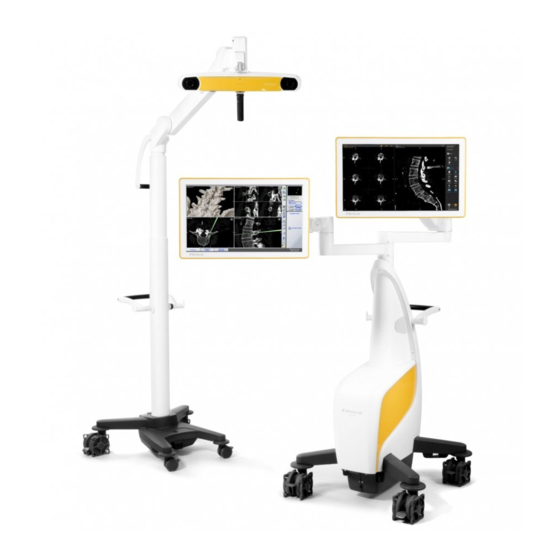
The below setup examples are only suggestions. For detailed setup descriptions please see the rel- Information evant Software User Guide. Curve Dual Display Both monitors facing the user for enhanced software interaction: Setup - Example 1 Figure 3 System User Guide Rev. 1.0 Curve Dual Display, Curve Single Display Ver. 1.0... - Page 24 Maximum extension of Monitor Cart - Curve Dual Display: Setup - Example 2 • Possibility to use second touchscreen, e.g., for unsterile software interaction • Maximum distance between patient and Monitor Cart body Figure 4 System User Guide Rev. 1.0 Curve Dual Display, Curve Single Display Ver. 1.0...
- Page 25 SYSTEM OVERVIEW Curve Single Display - Setup Example Figure 5 System User Guide Rev. 1.0 Curve Dual Display, Curve Single Display Ver. 1.0...
-
Page 26: Proper System Handling
Proper System Handling 2.4.1 Overview Classification The Monitor Cart and the Camera Cart - Curve Dual Display are classified as Class I Equipment according to IEC 60601-1 and must be tested accordingly. Classification Definition Refers to equipment classification regarding protection against electric Class I shock. - Page 27 Do not place Camera Cart, Monitor Cart or any parts thereof over the patient. System Radio The Curve Dual Display system is available with radio devices, which can be set to “enabled” or Devices “disabled” by default, including the below configurations: •...
- Page 28 NOTE: For more information on the operating and storage environment restrictions, see the Technical User Guide. Protection Covers Keep protection covers in a clean and dry place during surgery. System User Guide Rev. 1.0 Curve Dual Display, Curve Single Display Ver. 1.0...
-
Page 29: Inspections
All servicing and maintenance is to be carried out by trained Brainlab authorized technicians. Expected Service Brainlab provides a minimum of five years of service for platforms. During this period of time, spare Life parts as well as field support are offered. -
Page 30: Annual Inspection
Automatically performed by Brainlab. Contact Brainlab support for arrangement. Scope This inspection covers all components and functions as well as the items specified on the safety in- spection form. System User Guide Rev. 1.0 Curve Dual Display, Curve Single Display Ver. 1.0... -
Page 31: Weekly And Monthly Inspections
To optimize battery lifetime of the UPS it is recommended to fully discharge the battery once every three months. System User Guide Rev. 1.0 Curve Dual Display, Curve Single Display Ver. 1.0... -
Page 32: Safety Inspection
• Informs Brainlab immediately in writing if the equipment is deemed unsafe Inspections by • If a suitably qualified person is not available at the customer site, Brainlab support will perform Brainlab Personnel this inspection for a set fee. -
Page 33: Malfunctions And Return Instructions
Steps Turn off system. Unplug system from wall outlet. NOTE: If applicable, unplug the mains power cable from the Camera Cart - Curve Dual Display. Contact Brainlab support. Attach a notice such as “DO NOT USE” to equipment to prevent it from being used inadvertently. -
Page 34: Return Instructions
Westchester, IL 60154 Brainlab Ltd. Brainlab KK RMA Dept. RMA Dept. Tamachi East Bldg. 2F 100 Queen’s Road Central 3-2-16 Shibaura, Hong Kong Minato-ku, Tokyo 108-0023 Japan System User Guide Rev. 1.0 Curve Dual Display, Curve Single Display Ver. 1.0... -
Page 35: Monitor Cart
MONITOR CART Chapter Overview 3.1.1 Contents Topics Covered Section Components Page 36 Cart Arms and Monitors Page 38 Panels and System Ventilation Page 47 Cabling Page 57 System User Guide Rev. 1.0 Curve Dual Display, Curve Single Display Ver. 1.0... -
Page 36: Components
Wireless communication antenna (Curve Dual Display only) Page 69 Cable storage hooks Page 60 Adjustable monitor arm Page 44 Touchscreen monitor Page 38 Transport handle Page 112 Power connection Page 58 System User Guide Rev. 1.0 Curve Dual Display, Curve Single Display Ver. 1.0... - Page 37 MONITOR CART Back and Sound Panels Figure 8 Component Storage flap Page 60 Connection panel Page 49 User panel Page 47 Sound panel Page 53 System User Guide Rev. 1.0 Curve Dual Display, Curve Single Display Ver. 1.0...
-
Page 38: Cart Arms And Monitors
Viewing options vary depending on the software application and user preferences. For more infor- mation see the relevant Software User Guide. The Curve Dual Display system has two touchscreens, with which numerous combinations are pos- sible for displaying Brainlab software, including and external data sources. - Page 39 • When the system is powered on, the touchscreen(s) are always on and can be used. • Only one interaction is recognized at a time. • Curve Dual Display only: Depending on the software used, input on one touchscreen may affect what is displayed on the other (see relevant Software User Guide).
- Page 40 Do not attach or hang anything on the Monitor Cart arms. This may cause the cart to tip over. Do not lean on the Monitor Cart arms. System User Guide Rev. 1.0 Curve Dual Display, Curve Single Display Ver. 1.0...
-
Page 41: Range Of Motion
• Approximately 1 - 1.5 m above the ground. • With an rotation of 30° - 60° depending on the ideal height for the surgical set-up. 1499 mm ±50° (± 2°) 1007 mm Figure 11 System User Guide Rev. 1.0 Curve Dual Display, Curve Single Display Ver. 1.0... - Page 42 Cart Arms and Monitors Cart Arms • The arm of the Curve Single Display and the lower arm of the Curve Dual Display can be rotated 330° around the Monitor Cart center joint with a restricted area of 30° at the backside of the device.
- Page 43 MONITOR CART Articulated Arm 165° 165° Figure 13 Monitor Rotation The monitors can be rotated 180° around the vertical display axis. 90° 90° Figure 14 System User Guide Rev. 1.0 Curve Dual Display, Curve Single Display Ver. 1.0...
-
Page 44: Positioning Monitors
Move the Monitor Cart arms carefully to avoid clamping fingers or other body parts be- tween elements of the Monitor Cart arms or other system joints. When moving a monitor on the Curve Dual Display, be aware that the second monitor may also move unintentionally. - Page 45 • Ensure that you will not injure anyone or damage equipment (e.g., if the second monitor is unin- tentionally moved). NOTE: For information on how to move Monitor Cart into transport position, see page 104. System User Guide Rev. 1.0 Curve Dual Display, Curve Single Display Ver. 1.0...
-
Page 46: Locking Monitors
• Before docking the system • Before transportation • Curve Dual Display only: Before using motorized camera controls, especially if using a Sterile Touchpen to press camera control buttons (see page 92) System User Guide Rev. 1.0 Curve Dual Display, Curve Single Display Ver. 1.0... -
Page 47: Panels And System Ventilation
Figure 16 Component CD/DVD drive Page 48 On/off switch Page 88 UPS LED Page 56 Error LED Page 56 Mains power switch Page 88 USB ports Page 50 System User Guide Rev. 1.0 Curve Dual Display, Curve Single Display Ver. 1.0... - Page 48 • DVD 4,7GB (DVD±R, DVD±RW, DVD-RAM) • Double Layer±R • CD-R • CD-RW Only insert standard CD/DVDs of 120 mm diameter. Do not insert irregularly shaped CD/DVDs. System User Guide Rev. 1.0 Curve Dual Display, Curve Single Display Ver. 1.0...
- Page 49 2 port is covered on the Curve Single Display system. Imaging ports: • SDI In • Composite In • Camera • Serial • S-Video In • Microscope System User Guide Rev. 1.0 Curve Dual Display, Curve Single Display Ver. 1.0...
- Page 50 Serial communication port (female SUBD 9 pin cable). Serial Always fix the screws to lock the cable connector. System User Guide Rev. 1.0 Curve Dual Display, Curve Single Display Ver. 1.0...
- Page 51 Please note that local laws take priority over the above-mentioned require- ments. In doubt, consult your local representative or the technical service department. NOTE: Unless otherwise specified, the use of multiple socket outlet(s) is not permitted. System User Guide Rev. 1.0 Curve Dual Display, Curve Single Display Ver. 1.0...
- Page 52 Do not connect equipment to an unsecured network. Only operate the system in secured network environments. Otherwise, system func- tion cannot be guaranteed due to possible malicious software infections. System User Guide Rev. 1.0 Curve Dual Display, Curve Single Display Ver. 1.0...
-
Page 53: Sound Panel
Brainlab support. Docking station: standard connection for iPhone or iPod touch Aux-In: Stereo jack for external, battery-powered music source Mute button Mute LED (see page 54) System User Guide Rev. 1.0 Curve Dual Display, Curve Single Display Ver. 1.0... - Page 54 Mute is activated. Sounds from the connected device are not audible. Stereo Jack Connector to connect an external passive music source via an audio cable (max. 3 m) with 3.5 mm stereo jack. System User Guide Rev. 1.0 Curve Dual Display, Curve Single Display Ver. 1.0...
-
Page 55: System Ventilation
Do not place system near or over a radiator or heat register or in direct sunlight. Place computer in a small enclosure only if sufficiently ventilated. System User Guide Rev. 1.0 Curve Dual Display, Curve Single Display Ver. 1.0... -
Page 56: Led Indications
Malfunction has been detected (see page 33). Contact Brainlab Solid support. CD/DVD LED Color Status Explanation CD/DVD not being accessed or no CD/DVD inserted. Green Flashing CD/DVD is being accessed. System User Guide Rev. 1.0 Curve Dual Display, Curve Single Display Ver. 1.0... -
Page 57: Cabling
(Yellow/Green) conductive parts of other objects during operation Cable Before using the system, connect the potential equalization cable to the Monitor Cart and the corresponding wall outlet. System User Guide Rev. 1.0 Curve Dual Display, Curve Single Display Ver. 1.0... - Page 58 How to Connect Potential Equalization Cable Figure 20 Steps Plug potential equalization cable into potential equalization port of Monitor Cart Plug potential equalization cable into an equivalent wall outlet. System User Guide Rev. 1.0 Curve Dual Display, Curve Single Display Ver. 1.0...
- Page 59 Always remove the mains power cable from the wall outlet first, before unplugging the cable from the system. Connecting Camera For information on connecting Camera Cart to the Monitor Cart using the camera cable, see page 68. System User Guide Rev. 1.0 Curve Dual Display, Curve Single Display Ver. 1.0...
-
Page 60: Cable Storage
(see page 36). Even if you plan to use wireless camera communication with the Curve Dual Display system, store the camera cable on the cable hooks or in the storage flap at all times in case wireless communica- tion fails. -
Page 61: Camera Cart
CAMERA CART CAMERA CART Chapter Overview 4.1.1 Contents Topics Covered Section Cart Components Page 62 Cabling Page 67 Camera Use Page 71 LEDs and Acoustic Signals Page 85 System User Guide Rev. 1.0 Curve Dual Display, Curve Single Display Ver. 1.0... -
Page 62: Cart Components
Page 112 Telescopic post Page 83 Height adjustment handle Page 83 Motor control unit Page 80 Motorized joint Page 80 Camera Page 66 Camera handle Page 77 System User Guide Rev. 1.0 Curve Dual Display, Curve Single Display Ver. 1.0... - Page 63 Wireless communication antenna (not visible) Page 69 Docking release mechanism Page 101 On/off switch for camera motors Page 80 Mains power plug (for wireless communication) Page 69 System User Guide Rev. 1.0 Curve Dual Display, Curve Single Display Ver. 1.0...
-
Page 64: Camera Cart - Curve Single Display
Camera Cart - Curve Single Display Components Figure 24 Component Camera Cart base Page 65 Transport handle with cable hooks Page 112 Post Page 77 Camera Page 66 Camera handle Page 77 System User Guide Rev. 1.0 Curve Dual Display, Curve Single Display Ver. 1.0... - Page 65 Component Wheels with cable deflector and double-sided brakes Page 98 Small wheels with single-sided brakes Page 98 Camera cable connection Page 67 Docking release mechanism Page 101 System User Guide Rev. 1.0 Curve Dual Display, Curve Single Display Ver. 1.0...
-
Page 66: Camera
The infrared LED array is located around the inner ring of the lenses. The infrared LED array is a “Class I LED product”. Do not directly look into the infrared LED array at a distance less than 15 cm. System User Guide Rev. 1.0 Curve Dual Display, Curve Single Display Ver. 1.0... -
Page 67: Cabling
Cabling 4.3.1 Cable Attachment General Both the Curve Single Display and Curve Dual Display systems offer wired camera communica- Information tion with the Monitor Cart. The cabling procedure for wired camera communication is described be- low. Follow the cabling procedure on page 70, for the use of wireless camera communication with the Curve Dual Display system. - Page 68 Cabling Disconnecting Camera Cable Figure 27 When disconnecting cables, do not twist the plug. Grasp the plug, rather than the ca- ble, and pull it straight out. System User Guide Rev. 1.0 Curve Dual Display, Curve Single Display Ver. 1.0...
-
Page 69: Wireless Camera Communication
4.3.2 Wireless Camera Communication General The Camera Cart - Curve Dual Display offers wireless communication with the Monitor Cart. Information Only use one wireless device at a time. Only use wireless devices specified by Brainlab. NOTE: If the wireless connection is not functioning properly or if it is weak, use the cable to connect the camera to the Monitor Cart. - Page 70 Cabling How to Attach For wireless camera communication with the Curve Dual Display system, follow the below cabling Cables for Wireless procedure: Camera Communication Steps Ensure that Monitor Cart is turned off. Plug in Camera Cart mains power (see page 70).
-
Page 71: Camera Use
Information • Enable mobile positioning of camera • Allow adjustment of angle and height of camera • Can be attached via cable to the Monitor Cart (or communicate wirelessly with Curve Dual Display) Safe Use Only one person should operate the Camera Cart at any given time. - Page 72 When the Camera Cart is connecting via cable to the Monitor Cart, the Camera Cart is powered on as soon as the Monitor Cart is turned on (see page 89). When using wireless communication with the Curve Dual Display, the camera mains power must be plugged in and turned on (see page 70).
-
Page 73: Range Of Motion
• A distance of at least 520 mm from the base (when adjusted to a height of 2300 mm) • A rotation of 160° around the post 520 mm 160° Figure 28 System User Guide Rev. 1.0 Curve Dual Display, Curve Single Display Ver. 1.0... - Page 74 Camera Use Camera Cart Height The below minimum and maximum height values refer to the range of motion of the Camera Cart - Curve Dual Display (first value) and Camera Cart - Curve Single Display (second value). 2194 mm/ 2530 mm...
- Page 75 CAMERA CART Camera Range of The camera can be: Motion • Pivoted 90° in one direction • Angled 30° upward and 90° downward 90° 30° 90° Figure 30 System User Guide Rev. 1.0 Curve Dual Display, Curve Single Display Ver. 1.0...
-
Page 76: Operating Position
Safe Positioning Lock all four wheel brakes when Camera Cart is in operating position. Do not place Camera Cart or any of its parts over the patient. System User Guide Rev. 1.0 Curve Dual Display, Curve Single Display Ver. 1.0... -
Page 77: Adjusting Camera Position
System Joints When adjusting the arm of the cart, be careful that fingers or other body parts do not accidentally become pinched in the joints of the system. System User Guide Rev. 1.0 Curve Dual Display, Curve Single Display Ver. 1.0... - Page 78 Be extremely careful not to clamp fingers or other body parts when positioning the Camera Cart. Camera Cart joints that may clamp body parts include, but are not limited to: Camera Cart post Camera axis Camera arm and post System User Guide Rev. 1.0 Curve Dual Display, Curve Single Display Ver. 1.0...
- Page 79 System User Guide Rev. 1.0 Curve Dual Display, Curve Single Display Ver. 1.0...
- Page 80 Check the camera field of view in the software to ensure that all required marker spheres are visible (see relevant Software User Guide). NOTE: If motorized camera controls are not working, check the Camera Cart on/off switch (see page 81). System User Guide Rev. 1.0 Curve Dual Display, Curve Single Display Ver. 1.0...
- Page 81 Brainlab support. You can continue the surgery, using manual camera adjustment if necessary (see page 77). Track- ing is not affected. System User Guide Rev. 1.0 Curve Dual Display, Curve Single Display Ver. 1.0...
- Page 82 Figure 34 Steps While holding the camera handle , pull the rotation knob and rotate the camera 90°. Release the rotation knob, ensuring that it locks into position. System User Guide Rev. 1.0 Curve Dual Display, Curve Single Display Ver. 1.0...
- Page 83 Push up or pull down on handle to adjust the telescopic post. When adjusting the camera height, be aware that the suspended arm may move unin- tentionally. System User Guide Rev. 1.0 Curve Dual Display, Curve Single Display Ver. 1.0...
- Page 84 Ensure that all highly reflective items or sources of light do not obstruct the camera’s view. Artifacts caused by reflections can reduce accuracy, especially during registra- tion. System User Guide Rev. 1.0 Curve Dual Display, Curve Single Display Ver. 1.0...
-
Page 85: Leds And Acoustic Signals
CAMERA CART LEDs and Acoustic Signals 4.5.1 Overview Illustration Figure 37 Component Power LED Status LED Error LED System User Guide Rev. 1.0 Curve Dual Display, Curve Single Display Ver. 1.0... - Page 86 Solid amber • Contact Brainlab support (even if navigation is still possible). NOTE: If there is no signal from the power LED or status LED, contact Brainlab support (even if navigation is still possible). Acoustic Signals Camera emits two beeps when: •...
-
Page 87: Using The System
USING THE SYSTEM USING THE SYSTEM Chapter Overview 5.1.1 Contents Topics Covered Section Powering System On Page 88 System Shutdown Page 90 Sterile Use Page 92 System User Guide Rev. 1.0 Curve Dual Display, Curve Single Display Ver. 1.0... -
Page 88: Powering System On
Only establish or interrupt an electrical connection when all associated devices are fully turned off. Only operate the system using the mains power cable provided with the system. System User Guide Rev. 1.0 Curve Dual Display, Curve Single Display Ver. 1.0... -
Page 89: Turning On System
Ensure that all required cables have been connected at the connection panel (see page 49). Plug in mains power at Monitor Cart (page 59). If using wireless camera communication with Curve Dual Display: Plug in mains power at Camera Cart (see page 70). Turn on mains power switch Wait until the blue mains power LED is lit and solid. -
Page 90: System Shutdown
When the power LED turns off, unplug and secure all cables, storage devices and MP3 players. If applicable, unplug the mains power cable from the Camera Cart - Curve Dual Display. The on/off button does not disconnect the Monitor Cart from mains voltage. Use the... - Page 91 Apply mains power or shut down the system to avoid irre- versible loss of data. Loss of Data Failure to follow system shutdown procedure prior to disconnecting power may result in irreversible loss of data. System User Guide Rev. 1.0 Curve Dual Display, Curve Single Display Ver. 1.0...
-
Page 92: Sterile Use
Do not use the Sterile Camera Handle Sleeve if it rips or becomes damaged during mounting. How to Remove Packaging Figure 39 Steps Have a second person open and peel back packaging. Remove Sterile Camera Handle Sleeve from packaging. System User Guide Rev. 1.0 Curve Dual Display, Curve Single Display Ver. 1.0... - Page 93 , pull the sleeve off. NOTE: Avoid coming in contact with the camera cable when adjusting the camera sterilely. Verify that Sterile Camera Handle Sleeve has snapped properly into place. System User Guide Rev. 1.0 Curve Dual Display, Curve Single Display Ver. 1.0...
-
Page 94: Sterile Touchscreen Use
Verify prior to opening that the expiration date on the sterile packaging has not lapsed. If the product has expired, dispose of it immediately. Only use the Sterile Touchpen to control the software. Do not use sharp tools on the touchscreen. System User Guide Rev. 1.0 Curve Dual Display, Curve Single Display Ver. 1.0... - Page 95 Sterile Touchpen. The Sterile Touchpen is delivered sterile. If the Sterile Touchpen comes in contact with an unsterile environment during unpacking or use, dispose of it immediately. System User Guide Rev. 1.0 Curve Dual Display, Curve Single Display Ver. 1.0...
- Page 96 Sterile Touchpen. If the Sterile Touchpen comes in contact with the patient or fluids, dispose of it immediately. Disposal To maintain sterility, dispose of the Sterile Touchpen after each touchscreen interac- tion. System User Guide Rev. 1.0 Curve Dual Display, Curve Single Display Ver. 1.0...
-
Page 97: Transport
Contents Topics Covered Section Locking and Unlocking Brakes Page 98 Docking Camera and Monitor Carts Page 101 Transporting the System Page 112 Parking and Storage Page 116 System User Guide Rev. 1.0 Curve Dual Display, Curve Single Display Ver. 1.0... -
Page 98: Locking And Unlocking Brakes
Each wheel has an individual foot brake so that it can be easily transported and securely parked. Information Fully lock all brakes when the carts are stored, parked or in operation. Before Transport Release all brakes before moving the system. System User Guide Rev. 1.0 Curve Dual Display, Curve Single Display Ver. 1.0... -
Page 99: Monitor Cart Brakes
To lock, push the brake pedal down with your foot it snaps into locked position To unlock, push brake pedal up until it snaps into unlocked position System User Guide Rev. 1.0 Curve Dual Display, Curve Single Display Ver. 1.0... -
Page 100: Camera Cart Brakes
To lock, push the brake pedal down with your foot it snaps into locked position To unlock, push brake pedal up until it snaps into unlocked position System User Guide Rev. 1.0 Curve Dual Display, Curve Single Display Ver. 1.0... -
Page 101: Docking Camera And Monitor Carts
Disconnect camera from Monitor Cart. Clean touchscreens before applying the monitor protection covers (see page 120). Monitor Cover (Front) Figure 46 System User Guide Rev. 1.0 Curve Dual Display, Curve Single Display Ver. 1.0... - Page 102 After the monitor has cooled down, pull monitor protection cover over the monitor. Ensure that cover sits properly on monitor. Secure Velcro fasteners at back of monitor protection cover. System User Guide Rev. 1.0 Curve Dual Display, Curve Single Display Ver. 1.0...
- Page 103 Camera must be secured with the protection cover strap to prevent unintentional movement during transport. To avoid overheating, ensure that the camera has been turned off for at least five min- utes before applying the protection cover. System User Guide Rev. 1.0 Curve Dual Display, Curve Single Display Ver. 1.0...
-
Page 104: Transport And Parking Position
Ensure that the arms of the Camera and Monitor Carts do not hit people or surround- ings while it is being moved or adjusted. System User Guide Rev. 1.0 Curve Dual Display, Curve Single Display Ver. 1.0... - Page 105 The lower arm is now in final position. Fix all screwable locks on this arm to avoid unintentional movement (see page 46). System User Guide Rev. 1.0 Curve Dual Display, Curve Single Display Ver. 1.0...
- Page 106 Docking Camera and Monitor Carts Steps If you are using a Monitor Cart - Curve Dual Display, repeat steps 1-6 with the upper arm. NOTE: When repeating step 1, if you follow the direction indicated on the parking label. If the arm stops short, move the upper arm 90°...
- Page 107 NOTE: If the post is in a low position, the parking label may be covered. Use one or two hands to move the post up or down until the parking label aligns with the fixed section of the post. System User Guide Rev. 1.0 Curve Dual Display, Curve Single Display Ver. 1.0...
- Page 108 (when standing behind the cart). Use the camera protection cover to secure the camera and fix the position. An extended camera arm could hit persons while the post is being moved. System User Guide Rev. 1.0 Curve Dual Display, Curve Single Display Ver. 1.0...
- Page 109 Use the camera handle to rotate the camera to the left (when standing behind the cart). Use the camera protection cover to secure the camera and fix the position. System User Guide Rev. 1.0 Curve Dual Display, Curve Single Display Ver. 1.0...
-
Page 110: Docking And Undocking Procedure
Do not try attempt to dock anything other than the Camera Cart to the Monitor Cart. Final Docked Position - Curve Dual Display Figure 52 System User Guide Rev. 1.0 Curve Dual Display, Curve Single Display Ver. 1.0... - Page 111 “undocked” position Re-dock the carts. How to Undock Steps Push docking pedal down to open locking mechanism. Pull Camera Cart away from Monitor Cart. System User Guide Rev. 1.0 Curve Dual Display, Curve Single Display Ver. 1.0...
-
Page 112: Transporting The System
Tilted surfaces may cause the system to tip over. Unintentional Movement When moving the Camera Cart, be aware that the suspended arm may move uninten- tionally. System User Guide Rev. 1.0 Curve Dual Display, Curve Single Display Ver. 1.0... - Page 113 Do not move the system by pulling on the cables. System transportation should be supervised by at least one person to avoid collisions with other equipment, structures or people. System User Guide Rev. 1.0 Curve Dual Display, Curve Single Display Ver. 1.0...
-
Page 114: Proper Transport Procedure
NOTE: Be careful not to lift the cart so much that it tips over. Re-dock carts (see page 110) before continuing with transportation. System User Guide Rev. 1.0 Curve Dual Display, Curve Single Display Ver. 1.0... - Page 115 Do not transport or store the system outside of the environmental conditions speci- fied in the Technical User Guide. Failure to do so may cause the camera to lose its cal- ibration accuracy. System User Guide Rev. 1.0 Curve Dual Display, Curve Single Display Ver. 1.0...
-
Page 116: Parking And Storage
Never park the system or take the system out of transport position on a surface with >5° tilt. Safe Parking The system may only be parked on level surfaces. Ensure that all wheel brakes are locked when parked. System User Guide Rev. 1.0 Curve Dual Display, Curve Single Display Ver. 1.0... -
Page 117: Storage
When storing the system, always keep the carts docked together in the secure trans- port and parking position (see page 104). Environmental See the Technical User Guide for detailed environmental restrictions. Requirements System User Guide Rev. 1.0 Curve Dual Display, Curve Single Display Ver. 1.0... -
Page 118: Long Term Storage
Start system and verify correct function before using it for surgery (see page 88). Disposal If you do not intend to use the system again, please follow the disposal information on page 9. System User Guide Rev. 1.0 Curve Dual Display, Curve Single Display Ver. 1.0... -
Page 119: Cleaning
CLEANING Chapter Overview 7.1.1 Contents Topics Covered Section Overview Page 120 Curve System Page 122 Protection Cover for Monitors Page 124 Protection Cover for Camera Page 125 System User Guide Rev. 1.0 Curve Dual Display, Curve Single Display Ver. 1.0... -
Page 120: Cleaning Instructions
Ensure that liquid does not enter the Curve components, as this could damage the component and/or the electronics. Use only a moist cloth for cleaning. Other methods could allow liquids to enter the system and cause damage. System User Guide Rev. 1.0 Curve Dual Display, Curve Single Display Ver. 1.0... - Page 121 Incidin Plus 2% Meliseptol 70% Isopropyl 89% Monitor and Camera Cart Monitor Cart - yellow panels Monitor touchscreen Monitor housing Camera and camera lenses Monitor cover Camera cover System User Guide Rev. 1.0 Curve Dual Display, Curve Single Display Ver. 1.0...
-
Page 122: Curve System
NOTE: Take care not to wipe debris from the camera case onto the illuminator filters and lenses. Carefully clean interfaces, ensuring that no liquids enter the system. System User Guide Rev. 1.0 Curve Dual Display, Curve Single Display Ver. 1.0... - Page 123 Regularly inspect illuminator filter and lenses for cleanness, however only clean them when neces- sary. Post-Cleaning After cleaning, ensure that the telescope post of the Camera Cart - Curve Dual Display is complete- ly dry before retracting the post. System User Guide Rev. 1.0 Curve Dual Display, Curve Single Display Ver. 1.0...
-
Page 124: Protection Cover For Monitors
Do not wash, soak, iron or sterilize protection covers. Do Not Use • Acid solvents • Caustic solvents with pH value higher than 9.5 System User Guide Rev. 1.0 Curve Dual Display, Curve Single Display Ver. 1.0... -
Page 125: Protection Cover For Camera
Do not wash, soak, iron, disinfect or sterilize protection covers. Do Not Use • Acid solvents • Caustic solvents with pH value higher than 9.5 System User Guide Rev. 1.0 Curve Dual Display, Curve Single Display Ver. 1.0... - Page 126 Cleaning Instructions System User Guide Rev. 1.0 Curve Dual Display, Curve Single Display Ver. 1.0...
- Page 127 ......................disposal instructions procedure ......................... docking pedal manuals ................... docking system medical electrical systems ............. documentation monitor cart ......................DVD compatibility positioning System User Guide Rev. 1.0 Curve Dual Display, Curve Single Display Ver. 1.0...
- Page 128 ............. storage ..............stylus ..............support ............switching on symbols .......... hardware components ............user guide ............. system pairing ..........system transport ..........system ventilation System User Guide Rev. 1.0 Curve Dual Display, Curve Single Display Ver. 1.0...
- Page 130 Art-No: 60908-70EN *60908-70EN*...
Need help?
Do you have a question about the CURVE DUAL and is the answer not in the manual?
Questions and answers