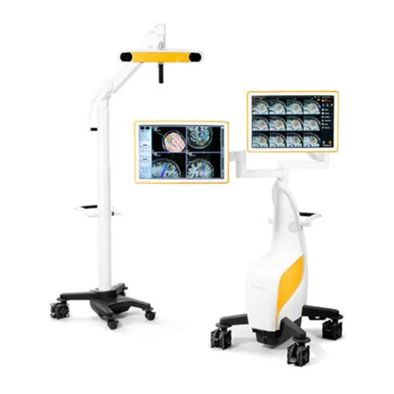
Brainlab CURVE System And Technical User Manual
Dual navigation station
Hide thumbs
Also See for CURVE:
- System user's manual (138 pages) ,
- Technical user manual (90 pages) ,
- System setup (4 pages)

Related Manuals for Brainlab CURVE


Summary of Contents for Brainlab CURVE
- Page 1 CURVE DUAL NAVIGATION STATION Version 1.2 System and Technical User Guide Revision 1.0 Copyright 2018, Brainlab AG Germany. All rights reserved.
-
Page 3: Table Of Contents
3.3.4 System Ventilation..........................47 3.3.5 LED Indications ..........................48 3.4 Cabling ..............................49 3.4.1 Cable Connection..........................49 3.4.2 Cable Storage ..........................52 3.5 UPS ..............................53 3.5.1 Overview ............................53 3.5.2 UPS Signals .............................54 System and Technical User Guide Rev. 1.0 Curve Dual Navigation Station Ver. 1.2... - Page 4 7.1 Locking and Unlocking Brakes ....................105 7.1.1 Monitor Cart Brakes ........................106 7.1.2 Camera Cart Brakes........................107 7.2 Docking Camera and Monitor Carts ...................108 7.2.1 Before You Begin ..........................108 System and Technical User Guide Rev. 1.0 Curve Dual Navigation Station Ver. 1.2...
- Page 5 10.2.3 Safety Inspection Form - Recurrent Tests..................148 10.3 Performing Tests ..........................150 10.3.1 Protective Earth Resistance ......................150 10.3.2 Equipment Leakage Current......................151 10.3.3 Applied Part Leakage Current (Type BF) (for Optional EM Tracking Unit) ........154 System and Technical User Guide Rev. 1.0 Curve Dual Navigation Station Ver. 1.2...
- Page 6 12.1 Inspections ............................185 12.1.1 Overview ............................185 12.1.2 Annual Inspection by Brainlab ......................186 12.1.3 Further Inspections........................187 12.2 Malfunctions and Return Instructions ..................189 12.2.1 Malfunctions ..........................189 12.2.2 Return Instructions ........................190 System and Technical User Guide Rev. 1.0 Curve Dual Navigation Station Ver. 1.2...
-
Page 7: General Information
Fax: +81 3 3769 6901 Expected Service Life Brainlab provides eight years of service for Curve Dual Navigation Station. Brainlab provides a minimum of five years of service for EM Tracking Unit. During these periods of time, spare parts as well as field support are offered. -
Page 8: Legal Information
The CE label indicates that the Brainlab product complies with the essential re- quirements of Council Directive 93/42/EEC (the "MDD"). According to the principles set out in the MDD, Curve and the EM Tracking Unit are Class IIb products. Disposal Instructions Only dispose of electrical and electronic equipment in accordance with statutory regu- lations. - Page 9 The WLAN module included in this product cannot be accessed by end users. The FCC ID of the WLAN module is listed on the WLAN label attached to the Monitor Cart. Please contact Brainlab Support in case of any related questions.
-
Page 10: Symbols
Do not re-use NOTE: Indicates a medical device that is intended for one use, or for use on a single patient during a single procedure. Do not resterilize System and Technical User Guide Rev. 1.0 Curve Dual Navigation Station Ver. 1.2... - Page 11 Danger of clamping hand or other body parts in equipment Do not look directly into the laser beam or point laser beam into the patient’s face or eyes. System and Technical User Guide Rev. 1.0 Curve Dual Navigation Station Ver. 1.2...
- Page 12 Visual hint: how to dock/undock system Danger of tilting: Do not move system when brakes are locked or if device is blocked by obstacles Strong magnetic field System and Technical User Guide Rev. 1.0 Curve Dual Navigation Station Ver. 1.2...
-
Page 13: Using The System
The following describes the intended users of the system and their respective tasks: • The clinical team (e.g., nurses) is responsible for transporting the Curve into the OR, setting up and preparation of the system for sterile use prior to surgery with constant control of sterility during surgery as well as shutting down, tidying and storage of the system after surgery. - Page 14 Handle them carefully. MR Environment Warning The Curve system has not been tested in an MR environment and is therefore classified as MR unsafe. System Maintenance Do not carry out inspections or maintenance while Curve is being used for patient treatment.
-
Page 15: Training And Documentation
Disregarding the information in this user guide (including warnings and cautions) is considered abnormal use. Available User Guides NOTE: Available user guides vary depending upon the Brainlab product. If you have questions regarding the user guides you received, please contact Brainlab support. User Guide Contents •... - Page 16 Instrument Assembly If any instrumentation is used with this product, ensure that all instruments are correctly assembled according to the instructions within the corresponding Instrument User Guide. System and Technical User Guide Rev. 1.0 Curve Dual Navigation Station Ver. 1.2...
-
Page 17: System Overview
SYSTEM OVERVIEW SYSTEM OVERVIEW System Components Terminology The Curve Dual Navigation Station is referred to as “Curve system” in this user guide. It consists of the following parts: • Curve Dual Monitor Cart • Curve Dual Camera Cart • EM Tracking Unit Abbreviation UPS is used to abbreviate “uninterruptible power supply”... - Page 18 System Components interest is calculated. Brainlab software applications use this tracking unit input to display the three-dimensional position of the EM instruments relative to the EM Patient Reference. Electromagnetic Compatibility Special precautions regarding electromagnetic compatibility (EMC) must be installed and put into service according to the EMC information provided in this guide.
- Page 19 ⑧ EM Field Generator Related Links 3.2 Cart Arms and Monitors on page 31 4.1.2 Camera on page 59 5.1 EM Tracking Unit Components on page 77 System and Technical User Guide Rev. 1.0 Curve Dual Navigation Station Ver. 1.2...
-
Page 20: System Setup
Sterile Field The Curve system is unsterile. Warning Do not allow the camera, monitors or any other part of the Curve system to enter the sterile field. Interferences If camera’s infrared light interferes with other devices, reposition these devices and/or the camera so that the interference is resolved. - Page 21 • User and connection panels and the Camera Cart connector point away from the pa- tient NOTE: Do not position the camera, monitors or any other part of the Curve system direct- ly over the patient. Lock all brakes on the Monitor Cart and Camera Cart.
-
Page 22: Curve Em System Setup
Unpack and set up EM Tracking Unit. Move monitor into desired position. Connect all cables at the connection panel of the Monitor Cart. Connect EM instruments to the EM Base Station. System and Technical User Guide Rev. 1.0 Curve Dual Navigation Station Ver. 1.2... -
Page 23: Or Setups
The below setup examples are only suggestions. For detailed setup descriptions please see the relevant Software User Guide. Curve Setup - Example 1 Figure 2 Both monitors facing the user for enhanced software interaction. System and Technical User Guide Rev. 1.0 Curve Dual Navigation Station Ver. 1.2... - Page 24 • Possibility to use second touchscreen, (e.g., for unsterile software interaction) • Maximum distance between patient and Monitor Cart body Curve EM Setup Example For detailed setup descriptions please see the relevant Software User Guide. System and Technical User Guide Rev. 1.0 Curve Dual Navigation Station Ver. 1.2...
-
Page 25: Proper System Handling
Modification Do not make any modifications to the Curve system. Only Brainlab certified personnel may modify the system. System and Technical User Guide Rev. 1.0 Curve Dual Navigation Station Ver. 1.2... - Page 26 Warning Do not attempt to dismantle or assemble any components of the system. Altering the Curve system or using it outside of its intended use may result in severe harm to the patient, user or third party. Camera and Monitor The camera and monitors are highly precise and fragile electrical equipment.
- Page 27 Protection Covers Keep protection covers in a clean and dry place during surgery. Related Links 11.2 Environmental Requirements on page 164 11.3 System Specifications on page 165 System and Technical User Guide Rev. 1.0 Curve Dual Navigation Station Ver. 1.2...
- Page 28 Proper System Handling System and Technical User Guide Rev. 1.0 Curve Dual Navigation Station Ver. 1.2...
-
Page 29: Monitor Cart
Wheels with cable deflector and double-sided brakes ② ③ Medical computer unit ④ Power supply ⑤ Cable storage hooks ⑥ Adjustable monitor arm ⑦ Touchscreen monitor ⑧ Transport handle ⑨ Power connection System and Technical User Guide Rev. 1.0 Curve Dual Navigation Station Ver. 1.2... - Page 30 3.3 Panels and System Ventilation on page 39 3.3.3 Sound Panel on page 45 3.4 Cabling on page 49 7.1.1 Monitor Cart Brakes on page 106 7.3 Transporting the System on page 117 System and Technical User Guide Rev. 1.0 Curve Dual Navigation Station Ver. 1.2...
-
Page 31: Cart Arms And Monitors
Brainlab software, including external data sources. Not for Diagnostic Use Warning The Curve touchscreen does not comply with DIN EN 6868 and it is not intended for diagnostic use. Video images are not suitable for diagnostic use. Monitor Components ①... - Page 32 Do not attach or hang anything on the Monitor Cart arms. This may cause the cart to tip over. Do not lean on the Monitor Cart arms. Related Links 2.3 Proper System Handling on page 25 System and Technical User Guide Rev. 1.0 Curve Dual Navigation Station Ver. 1.2...
-
Page 33: Range Of Motion
Be aware that moving one arm may also move the other arm when the restricted area is reached. System and Technical User Guide Rev. 1.0 Curve Dual Navigation Station Ver. 1.2... - Page 34 Range of Motion 165° 165° 90° 90° System and Technical User Guide Rev. 1.0 Curve Dual Navigation Station Ver. 1.2...
- Page 35 MONITOR CART Articulated Arm 165° 165° Figure 10 Monitor Rotation The monitors can be rotated 180° around the vertical display axis. 90° 90° Figure 11 System and Technical User Guide Rev. 1.0 Curve Dual Navigation Station Ver. 1.2...
-
Page 36: Positioning Monitors
Follow these standard procedures points when adjusting monitor position: • Move lower arm before upper arm • Move inner joints first, working your way outward • Follow the direction located on the parking position labels System and Technical User Guide Rev. 1.0 Curve Dual Navigation Station Ver. 1.2... - Page 37 • Ensure that you will not injure anyone or damage equipment (e.g., if the second monitor is unintentionally moved) Related Links 7.2.2 Transport and Parking Position on page 110 System and Technical User Guide Rev. 1.0 Curve Dual Navigation Station Ver. 1.2...
-
Page 38: Locking Monitors
Tighten the locking knob if monitor/cart arm movement is still possible. Before using the system, lock the Monitor Cart joints into the required position using the locking knobs to avoid unintentional movement. System and Technical User Guide Rev. 1.0 Curve Dual Navigation Station Ver. 1.2... -
Page 39: Panels And System Ventilation
• DVD-RW • DVD+R 8.5GB (Double Layer) • DVD+RW 4.7GB • DVD-RAM 4.7GB The following CD/DVD types can be written to: • DVD 4,7GB (DVD±R, DVD±RW, DVD-RAM) System and Technical User Guide Rev. 1.0 Curve Dual Navigation Station Ver. 1.2... - Page 40 • Composite In 1 • SDI In 1 ③ Display Port ④ Data: • Hospital Network ⑤ • Intraoperative Data • Tracking Microscope: ⑥ • HUD • Communication System and Technical User Guide Rev. 1.0 Curve Dual Navigation Station Ver. 1.2...
- Page 41 To remove the cable press on the connector locking latch, then unplug the cable. Scan USB flash drives with an antivirus software before connecting them to the system. System and Technical User Guide Rev. 1.0 Curve Dual Navigation Station Ver. 1.2...
- Page 42 Only connect passive USB devices to the system, otherwise safety and effectiveness of the equipment cannot be guaranteed. Restrictions Connecting Equipment to Panels Curve EM is a medical electrical system consisting of the Monitor Cart and the EM Tracking Unit. Unless otherwise specified, the use of multiple socket outlet(s) is not permitted.
-
Page 43: Lan Connection
3.3.2 LAN Connection LAN Connection Depending on the Brainlab application that is running on the system and the integration into the hospital network, connecting a system to the network offers patient data transfer, remote access, streaming and session sharing. Only connect IEC compliant devices to the LAN ports. - Page 44 The wireless system communication may interfere with other nearby wireless devices. Verify the correct function of the wireless system connection and other necessary devices prior to surgery. System and Technical User Guide Rev. 1.0 Curve Dual Navigation Station Ver. 1.2...
-
Page 45: Sound Panel
Sound Panel Before Use Curve provides a holder that can hold a mobile device to play sound. Before attaching the MP3 player, always mute the sound system to avoid sudden or unexpected loud noises and/or startling people in the operating room. - Page 46 The sound system may skip or fail due to electrostatic discharge on the control buttons. In this case, turn off or unplug the MP3 player. After restarting the Curve system the sound system will be fully functional for the next session.
-
Page 47: System Ventilation
Do not place system near or over a radiator or heat register or in direct sunlight. Place computer in a small enclosure only if sufficiently ventilated. System and Technical User Guide Rev. 1.0 Curve Dual Navigation Station Ver. 1.2... -
Page 48: Led Indications
Solid Malfunction has been detected. Contact Brainlab support. CD/DVD LED Color Status Explanation CD/DVD not being accessed or no CD/DVD inserted. Green Flashing CD/DVD is being accessed. System and Technical User Guide Rev. 1.0 Curve Dual Navigation Station Ver. 1.2... -
Page 49: Cabling
Warning Before using the system, connect the potential equalization cable to the Monitor Cart and the corresponding wall outlet. Related Links 4.2 Cabling on page 61 System and Technical User Guide Rev. 1.0 Curve Dual Navigation Station Ver. 1.2... - Page 50 Plug potential equalization cable ② into potential equalization port of Monitor Cart ①. Plug potential equalization cable into an equivalent wall outlet. How to Connect Mains Power Cable ① ② Figure 19 System and Technical User Guide Rev. 1.0 Curve Dual Navigation Station Ver. 1.2...
- Page 51 Check voltage setting before plugging mains power cable into wall outlet. Always remove the mains power cable from the wall outlet first, before unplugging the cable from the system. System and Technical User Guide Rev. 1.0 Curve Dual Navigation Station Ver. 1.2...
-
Page 52: Cable Storage
If a cable will remain connected to a cart, carefully bundle the cable together and hang it from the cable hooks. Related Links 3.1 Components on page 29 System and Technical User Guide Rev. 1.0 Curve Dual Navigation Station Ver. 1.2... -
Page 53: Ups
Powered Components If mains power is lost while using the Curve system, the complete Monitor and Camera Carts are powered for a maximum of five minutes (when battery is fully charged). In case of power failure while charging, battery may not run for the full five minutes. -
Page 54: Ups Signals
Long beep followed by until mains power is restored. Turn on system Battery empty short beeps again and allow UPS to charge for at least two hours. System and Technical User Guide Rev. 1.0 Curve Dual Navigation Station Ver. 1.2... -
Page 55: Ups Battery
NOTE: It is possible to use the Monitor Cart while the UPS is charging, however if mains power is lost, standby power will last less than five minutes. System and Technical User Guide Rev. 1.0 Curve Dual Navigation Station Ver. 1.2... - Page 56 UPS Battery System and Technical User Guide Rev. 1.0 Curve Dual Navigation Station Ver. 1.2...
-
Page 57: Camera Cart
Camera Cart base ② Transport handle with cable hooks ③ Telescopic post ④ Height adjustment handle ⑤ Motor control unit ⑥ Motorized joint ⑦ Camera ⑧ Camera handle System and Technical User Guide Rev. 1.0 Curve Dual Navigation Station Ver. 1.2... - Page 58 4.3.4 Adjusting Camera Position on page 68 7.1 Locking and Unlocking Brakes on page 105 7.3 Transporting the System on page 117 8.1.2 Cleaning the Curve System on page 129 System and Technical User Guide Rev. 1.0 Curve Dual Navigation Station Ver. 1.2...
-
Page 59: Camera
18-32 Vdc Power consumption 13.5 W Positioning Laser Specifications The camera contains a Class II positioning laser ②. Specification Value Wavelength 635 nm Maximum output 1 mW System and Technical User Guide Rev. 1.0 Curve Dual Navigation Station Ver. 1.2... - Page 60 • FDA/CDRH 21 CFR 1040.10 and 1040.11 (except for de- viations pursuant to Laser Notice No. 50 dated July 26, 2001) Related Links 8.1.2 Cleaning the Curve System on page 129 System and Technical User Guide Rev. 1.0 Curve Dual Navigation Station Ver. 1.2...
-
Page 61: Cabling
Cabling 4.2.1 Cable Attachment General Information The Curve system offers wired camera communication with the Monitor Cart. The cabling procedure is described below. Cabling Precautions Ensure that camera cable is not attached to any other device than the Monitor Cart. -
Page 62: Camera Use
Do not use any active wireless tool that is not specified by Brainlab. Do not use more than one active wireless tool at the same time. Communication with active wireless tools (such as Z-touch) can be established even when the camera is warming up. - Page 63 Every time camera is powered on, it generally requires a warm-up time of two minutes. If camera is stored at low temperatures, warm-up time may be longer. Related Links 6.1 Powering System On on page 97 System and Technical User Guide Rev. 1.0 Curve Dual Navigation Station Ver. 1.2...
-
Page 64: Range Of Motion
• Provides a distance of at least 520 mm from the base (when adjusted to a height of 2300 mm) • Provides a rotation of 160° around the post System and Technical User Guide Rev. 1.0 Curve Dual Navigation Station Ver. 1.2... - Page 65 CAMERA CART Camera Cart Height 2530 mm 650 mm Figure 25 The below minimum and maximum height values refer to the range of motion of the Camera Cart. System and Technical User Guide Rev. 1.0 Curve Dual Navigation Station Ver. 1.2...
- Page 66 The camera’s range of motion is as follows: • It can be pivoted 90° in one direction • It can be angled 30° upward and 90° downward System and Technical User Guide Rev. 1.0 Curve Dual Navigation Station Ver. 1.2...
-
Page 67: Operating Position
NOTE: The gas spring of the camera joint keeps the camera in desired position. Plug camera cable into Monitor Cart. Attach Sterile Camera Handle Sleeve to camera handle. System and Technical User Guide Rev. 1.0 Curve Dual Navigation Station Ver. 1.2... -
Page 68: Adjusting Camera Position
Be extremely careful not to clamp fingers or other body parts when positioning the Camera Cart. Camera Cart joints that may clamp body parts include, but are not limited to: Camera Cart post Camera axis Camera arm and post System and Technical User Guide Rev. 1.0 Curve Dual Navigation Station Ver. 1.2... - Page 69 The camera head can be adjusted vertically, horizontally and can be turned 90°. Step Grip camera handle or Sterile Camera Handle Sleeve and move camera to desired posi- tion. Use positioning laser to assist with adjustment. Release camera handle. System and Technical User Guide Rev. 1.0 Curve Dual Navigation Station Ver. 1.2...
- Page 70 Use the controls in the software to adjust the camera: A beeping sound is audible to confirm movement. NOTE: If motorized camera movement is not working, check the Camera Cart on/off switch. System and Technical User Guide Rev. 1.0 Curve Dual Navigation Station Ver. 1.2...
- Page 71 Turn off camera using the on/off switch ① and contact Brainlab support. ① Figure 29 You can continue the surgery, using manual camera adjustment if necessary. Tracking is not affected. System and Technical User Guide Rev. 1.0 Curve Dual Navigation Station Ver. 1.2...
- Page 72 While holding the camera handle ①, pull the rotation knob ② and rotate the camera 90°. Release the rotation knob, ensuring that it locks into position. Camera Cart Height Adjustment ① Figure 31 System and Technical User Guide Rev. 1.0 Curve Dual Navigation Station Ver. 1.2...
- Page 73 Push up or pull down on handle to adjust the telescopic post. Warning When adjusting the camera height, be aware that the suspended arm may move unintentionally. System and Technical User Guide Rev. 1.0 Curve Dual Navigation Station Ver. 1.2...
-
Page 74: Leds And Acoustic Signals
• Contact Brainlab support (even if navigation is still possi- Error LED ③ ble). • Camera defect. Solid amber • Contact Brainlab support (even if navigation is still possi- ble). System and Technical User Guide Rev. 1.0 Curve Dual Navigation Station Ver. 1.2... - Page 75 CAMERA CART NOTE: If there is no signal from the power LED or status LED, contact Brainlab support (even if navigation is still possible). Acoustic Signals Camera emits two beeps when: • Reset is performed • Power is applied to system •...
- Page 76 LEDs and Acoustic Signals System and Technical User Guide Rev. 1.0 Curve Dual Navigation Station Ver. 1.2...
-
Page 77: Em Tracking Unit
Warning To maintain tracking accuracy over the defined lifetime it is necessary to perform an accuracy test of the EM Tracking Unit every 3 years by Brainlab authorized personnel. Do not sterilize the EM Tracking Unit or its components. Warning EM Tracking Unit components are not suitable for use in the presence of flammable anesthetic mixtures containing air, oxygen or nitrous oxide. - Page 78 Power connection ② EM instrument LEDs ③ Power LED ④ EM instrument ports ⑤ Tool extension port (not used) ⑥ Navigation system port ⑦ EM Field Generator port System and Technical User Guide Rev. 1.0 Curve Dual Navigation Station Ver. 1.2...
-
Page 79: Em Tracking Unit Setup
Unit are not single-fault safe in terms of functional safety and thus may fail during operation. Do not drop the EM Field Generator or subject it to impacts. Physical damage to the Field Generator may alter the calibration. Inform Brainlab Support in case of the EM Field Generator was subjected to an impact. Disturbances A tracked instrument having a motorized element (e.g. -
Page 80: Setting Up Em Tracking Unit
5.2.2 Setting Up EM Tracking Unit EM Tracking Unit Transport Cases ① ② ③ Figure 34 Component ① Unsterile instrument case ② Bottom layer ③ Top layer System and Technical User Guide Rev. 1.0 Curve Dual Navigation Station Ver. 1.2... - Page 81 ⑩ EM Field Generator fixation piece Check the EM Field Generator Fixation Plate and Positioning Arm for visible damage before use and do not used if damaged. System and Technical User Guide Rev. 1.0 Curve Dual Navigation Station Ver. 1.2...
- Page 82 Do not sterilize the Field Generator Mounting Suspension. Cabling Precautions Warning Only use the power cables provided by Brainlab to power the EM Tracking Unit. Do not extend power cables. Warning Risk of electrical shock: Do not touch cable plugs when Monitor Cart is turned on.
- Page 83 Connect the EM cable to the Curve Monitor Cart. Replace top layer of transport case and store the case out of the way, where it will remain clean and dry. System and Technical User Guide Rev. 1.0 Curve Dual Navigation Station Ver. 1.2...
-
Page 84: Connecting Em Tracking Unit To Monitor Cart
Connect the data plug of the EM cable to the navigation system port of the EM Base Sta- tion ②. Connect the power plug of the EM cable to the power port of the EM Base Station ①. To connect to Curve Monitor Cart: System and Technical User Guide Rev. 1.0 Curve Dual Navigation Station Ver. 1.2... - Page 85 EM TRACKING UNIT Step • Connect the USB cable to the blue labeled USB connector ③ on the Curve Monitor Cart User Panel. ③ • Connect the EM power connector to the camera port on Curve Monitor Cart Connec- tion Panel ④.
- Page 86 Figure 39 Step Locate the power connector at the EM Base Station ①. Push the release trigger on the top of the plug ②. Pull plug out ③. System and Technical User Guide Rev. 1.0 Curve Dual Navigation Station Ver. 1.2...
-
Page 87: Connecting Em Instruments
When the EM instrument is recognized by the software as a valid, the LED color changes from amber to green. NOTE: Available EM instruments are described in the corresponding Instrument User Guide. System and Technical User Guide Rev. 1.0 Curve Dual Navigation Station Ver. 1.2... -
Page 88: Using The Em Tracking Unit
Do not attempt to disassemble or assemble any components of the EM Tracking Unit. Altering the EM Tracking Unit or using it outside of its intended use may result in severe harm to the patient, user or third party. System and Technical User Guide Rev. 1.0 Curve Dual Navigation Station Ver. 1.2... -
Page 89: Positioning Components
Do not place the EM Base Station and the Navigation Station less than 60 cm from the EM Field Generator as this may affect the tracking volume or the system accuracy. Positioning EM Field Generator Figure 41 System and Technical User Guide Rev. 1.0 Curve Dual Navigation Station Ver. 1.2... - Page 90 Do not operate the EM Field Generator within 200 mm of an installed pacemaker. The magnetic field produced by the EM Field Generator may interfere with the operation of the pacemaker. Ventilation Openings ① ③ ④ ② Figure 43 System and Technical User Guide Rev. 1.0 Curve Dual Navigation Station Ver. 1.2...
- Page 91 OR table may move components and pull on attached cables. Warning Do not move the EM Field Generator while tracking an instrument or reference, as this may affect navigation accuracy. System and Technical User Guide Rev. 1.0 Curve Dual Navigation Station Ver. 1.2...
-
Page 92: Positioning Patient
The navigation volume starts at 50 mm from the EM Field Generator front. The optimal working distance is between 100 and 350 mm from the EM Field Generator front. Component ① ② Side ③ Back System and Technical User Guide Rev. 1.0 Curve Dual Navigation Station Ver. 1.2... - Page 93 Use an appropriate head rest for the patient in order to set the head on a level where the face of the EM Field Generator approximately covers the area of interest, including EM instruments. System and Technical User Guide Rev. 1.0 Curve Dual Navigation Station Ver. 1.2...
-
Page 94: Leds And Acoustic Signals
• Contact Brainlab support if an EM instrument is connect- ed, the Monitor Cart and the EM Base Station are pow- ered on, but the LED remains off. System and Technical User Guide Rev. 1.0 Curve Dual Navigation Station Ver. 1.2... - Page 95 Acoustic Signals The EM Tracking Unit emits two beeps when: • Reset is performed. • Power is applied to system. • Connection is made to Brainlab software. System and Technical User Guide Rev. 1.0 Curve Dual Navigation Station Ver. 1.2...
- Page 96 LEDs and Acoustic Signals System and Technical User Guide Rev. 1.0 Curve Dual Navigation Station Ver. 1.2...
-
Page 97: Using The System
Only operate the system using the mains power cable provided with the system. If system has been turned off, wait at least 60 seconds before turning it on again. Otherwise, high input current may trip the circuit breaker. System and Technical User Guide Rev. 1.0 Curve Dual Navigation Station Ver. 1.2... - Page 98 Ensure that all required cables have been connected at the connection panel. Plug in mains power at Monitor Cart. Turn on mains power switch ④. The system starts automatically. System and Technical User Guide Rev. 1.0 Curve Dual Navigation Station Ver. 1.2...
-
Page 99: System Shutdown
Using the mains power switch before equipment has fully shut down may result in irreversible loss of data. Switch off mains power before connecting or disconnecting cables. System and Technical User Guide Rev. 1.0 Curve Dual Navigation Station Ver. 1.2... -
Page 100: Sterile Use
Do not use the Sterile Camera Handle Drape if it rips or becomes damaged during mounting. How to Remove Packaging Figure 49 Step Have a second person open and peel back packaging. Remove Sterile Camera Handle Drape from packaging. System and Technical User Guide Rev. 1.0 Curve Dual Navigation Station Ver. 1.2... - Page 101 To remove Sterile Camera Handle Drape ② from the camera handle ①, pull the drape off. NOTE: Avoid coming in contact with the camera cable ③ when adjusting the camera sterilely. Verify that Sterile Camera Handle Drape has snapped properly into place. System and Technical User Guide Rev. 1.0 Curve Dual Navigation Station Ver. 1.2...
-
Page 102: Sterile Monitor Drape
Dispose of the drape after use. How to Unpack Drape Step Make sure packaging has no holes. Peel open drape seal. Remove drape from packaging under sterile conditions. System and Technical User Guide Rev. 1.0 Curve Dual Navigation Station Ver. 1.2... - Page 103 Peel the adhesive liner off one of the adhesive strips on the lower part of the drape and attach it to monitor post. Repeat for the second adhesive strip on the lower part of the drape. System and Technical User Guide Rev. 1.0 Curve Dual Navigation Station Ver. 1.2...
- Page 104 Sterile Monitor Drape System and Technical User Guide Rev. 1.0 Curve Dual Navigation Station Ver. 1.2...
-
Page 105: Transport
Each wheel has an individual foot brake so that it can be easily transported and securely parked. Warning Fully lock all brakes when the carts are stored, parked or in operation. Before Transport Warning Release all brakes before moving the system. System and Technical User Guide Rev. 1.0 Curve Dual Navigation Station Ver. 1.2... -
Page 106: Monitor Cart Brakes
To lock, push the brake pedal ③ down with your foot until it snaps into locked position ①. To unlock, push brake pedal ③ up until it snaps into unlocked position ②. System and Technical User Guide Rev. 1.0 Curve Dual Navigation Station Ver. 1.2... -
Page 107: Camera Cart Brakes
To lock, push the brake pedal ③ down with your foot until it snaps into locked position ①. To unlock, push brake pedal ③ up until it snaps into unlocked position ②. System and Technical User Guide Rev. 1.0 Curve Dual Navigation Station Ver. 1.2... -
Page 108: Docking Camera And Monitor Carts
Clean touchscreens before applying the monitor protection covers. Monitor Cover (Front) Figure 54 Monitor Cover Back ① Figure 55 System and Technical User Guide Rev. 1.0 Curve Dual Navigation Station Ver. 1.2... - Page 109 Camera must be secured with the protection cover strap to prevent unintentional movement during transport. To avoid overheating, ensure that the camera has been turned off for at least five minutes before applying the protection cover. System and Technical User Guide Rev. 1.0 Curve Dual Navigation Station Ver. 1.2...
-
Page 110: Transport And Parking Position
Monitor Cart post. NOTE: Be aware that there is a fixation that causes the upper arm to move when the an- gle between both arms is 90°. System and Technical User Guide Rev. 1.0 Curve Dual Navigation Station Ver. 1.2... - Page 111 NOTE: When repeating step 1, if you follow the direction indicated on the parking label. If the arm stops short, move the upper arm 90° in the opposite direction and the parking la- bels will line up. System and Technical User Guide Rev. 1.0 Curve Dual Navigation Station Ver. 1.2...
- Page 112 Transport and Parking Position Step The Monitor Cart is then in final position. How to Position Camera Cart ② ① ③ Figure 58 System and Technical User Guide Rev. 1.0 Curve Dual Navigation Station Ver. 1.2...
- Page 113 Use one or two hands to move the post up or down until the parking label aligns with the fixed section of the post. Use the camera handle ② to fold the camera arm until it is firmly aligned at the post. System and Technical User Guide Rev. 1.0 Curve Dual Navigation Station Ver. 1.2...
- Page 114 Use the camera handle ② to rotate the camera to the left (when standing behind the cart). Use the camera protection cover to secure the camera and fix the position. System and Technical User Guide Rev. 1.0 Curve Dual Navigation Station Ver. 1.2...
-
Page 115: Docking And Undocking Procedure
Monitor Cart until locking mechanism audibly snaps into place. NOTE: It is recommended to always move the Camera Cart into the Monitor Cart and not the other way around. System and Technical User Guide Rev. 1.0 Curve Dual Navigation Station Ver. 1.2... - Page 116 “undocked” position ②. Re-dock the carts. How to Undock the Curve Carts Step Push docking pedal down ② to open locking mechanism. Pull Camera Cart away from Monitor Cart. System and Technical User Guide Rev. 1.0 Curve Dual Navigation Station Ver. 1.2...
-
Page 117: Transporting The System
• The system may not be moved or parked in any position if the ground has a tilt of more than 10°. Unintentional Movement Warning When moving the Camera Cart, be aware that the suspended arm may move unintentionally. System and Technical User Guide Rev. 1.0 Curve Dual Navigation Station Ver. 1.2... - Page 118 Ensure during transport that fingers or other body parts are not pinched in the joints of the system. Related Links 7.2.3 Docking and Undocking Procedure on page 115 System and Technical User Guide Rev. 1.0 Curve Dual Navigation Station Ver. 1.2...
-
Page 119: Proper Transport Procedure
How to Transport the Curve EM System Step Use the transport case ① to transport the EM Tracking Unit components. Use the handle ② to transport the Monitor Cart. System and Technical User Guide Rev. 1.0 Curve Dual Navigation Station Ver. 1.2... - Page 120 Pull the Monitor Cart to the point of depth variation, then carefully lift the handle while pulling it over the step. NOTE: Be careful not to lift the cart so much that it tips over. Re-dock carts before continuing with transportation. System and Technical User Guide Rev. 1.0 Curve Dual Navigation Station Ver. 1.2...
-
Page 121: Parking And Storage
Safe Parking Warning Ensure that all wheel brakes are locked when parked. Related Links 3.2.4 Locking Monitors on page 38 7.2.2 Transport and Parking Position on page 110 System and Technical User Guide Rev. 1.0 Curve Dual Navigation Station Ver. 1.2... -
Page 122: Storage
When storing the system, always keep the carts docked together in the secure transport and parking position. Related Links 7.2.2 Transport and Parking Position on page 110 11.2 Environmental Requirements on page 164 System and Technical User Guide Rev. 1.0 Curve Dual Navigation Station Ver. 1.2... -
Page 123: Transporting The Em Tracking Unit Using Transport Cases
While holding onto EM Field Generator ③, pull the release mechanism ② on the EM Field Generator Fixation Plate ① to separate EM Field Generator. Store EM Field Generator in the bottom layer of the transport case ⑤. System and Technical User Guide Rev. 1.0 Curve Dual Navigation Station Ver. 1.2... - Page 124 Store the EM Field Generator Positioning Arm in the top layer of the transport case ⑨. Put the unsterile instruments into the unsterile instrument case ⑪. Place the unsterile instrument case ⑪ into the transport case ⑩. System and Technical User Guide Rev. 1.0 Curve Dual Navigation Station Ver. 1.2...
-
Page 125: Long Term Storage
How to Retrieve Equipment Stored for 6 Months Before using equipment that has been stored for six months or longer: Step Clean the equipment. Contact Brainlab support to install a new UPS battery. System and Technical User Guide Rev. 1.0 Curve Dual Navigation Station Ver. 1.2... - Page 126 Step Fully recharge UPS battery. Perform a recurrent test to verify safety and effectiveness of equipment. Start system and verify correct function before using it for surgery. System and Technical User Guide Rev. 1.0 Curve Dual Navigation Station Ver. 1.2...
-
Page 127: Cleaning
(optical or electromagnetic) is disconnected from Monitor Cart. No Automatic Disinfection Do not use automatic cleaning and disinfection procedures for Curve components. Do not expose the Curve system to direct UV light, as it may damage equipment. No Sterilization Do not sterilize Curve system components. - Page 128 Cleaning Instructions Disinfectant Compatibility The following disinfectant types are compatible with all Curve system components, except for the camera: Disinfectant Type Example Alcohol-based Meliseptol, Mikrozid AF Liquid Alkylamine-based Incidin Plus 2% Active oxygen-based Perform Aldehyde/chloride-based Antiseptica Kombi - Flächendesinfektion NOTE: Use only surface disinfectants released in your specific market.
-
Page 129: Cleaning The Curve System
Brainlab to avoid damaging the system. Camera Cleaning Intervals As frequency of cleaning depends on how frequently the camera is used, Brainlab cannot give general recommendation on cleaning intervals. This is within the user’s responsibility. Regularly inspect illuminator filter and lenses for cleanness, however only clean them when necessary. - Page 130 NOTE: Do not spray liquids directly into ventilation openings of the EM Base Station. Wipe off the EM Field Generator fixation plate or Positioning Arm and remove dust and remnants of EM Field Generator fixation piece. System and Technical User Guide Rev. 1.0 Curve Dual Navigation Station Ver. 1.2...
-
Page 131: Protection Cover For Monitors
NOTE: If a soiled cover cannot be sufficiently cleaned using the above steps, exchange the cover for a new one. Do not wash, soak, iron or sterilize protection covers. System and Technical User Guide Rev. 1.0 Curve Dual Navigation Station Ver. 1.2... -
Page 132: Protection Cover For Camera
NOTE: If a soiled cover cannot be sufficiently cleaned using the above steps, exchange the cover for a new one. Do not wash, soak, iron, disinfect or sterilize protection covers. System and Technical User Guide Rev. 1.0 Curve Dual Navigation Station Ver. 1.2... -
Page 133: Transport Cases
Allow the transport cases to fully dry before inserting the system. NOTE: After drying, surface disinfectants may leave stains. System and Technical User Guide Rev. 1.0 Curve Dual Navigation Station Ver. 1.2... - Page 134 Transport Cases System and Technical User Guide Rev. 1.0 Curve Dual Navigation Station Ver. 1.2...
-
Page 135: Troubleshooting
TROUBLESHOOTING TROUBLESHOOTING Introduction Chapter Information This chapter contains troubleshooting information for the major components of the Curve system: • Monitor Cart • Monitor • UPS • Camera Cart • EM Tracking Unit The purpose of this chapter is to provide you with specific information in order to recognize possible problems and communicate them to Brainlab support. -
Page 136: Troubleshooting: Monitor Cart
Troubleshooting: Monitor Cart Power to the Monitor Cart Occurrence Possible Cause Check that the mains power cabling is correctly connected to No power to Monitor Cart power supply. System and Technical User Guide Rev. 1.0 Curve Dual Navigation Station Ver. 1.2... -
Page 137: Troubleshooting: Monitor
The backlight evenly illuminates the background of the active display so that pixels are visible. Occurrence Comment The backlight may need to be replaced (backlights The display is black. typically have a specified lifetime of five years). System and Technical User Guide Rev. 1.0 Curve Dual Navigation Station Ver. 1.2... -
Page 138: Touchscreen
Cursor position on the screen does not Calibration of the cursor has been lost. Contact Brain- correspond to the part of the screen lab support. touched System and Technical User Guide Rev. 1.0 Curve Dual Navigation Station Ver. 1.2... -
Page 139: Failure Indication Screens
No Signal! play signal has an error. In case of an error contact Brainlab Support. System and Technical User Guide Rev. 1.0 Curve Dual Navigation Station Ver. 1.2... -
Page 140: Troubleshooting: Ups
UPS emits a long beep followed by The UPS battery is completely empty. Fully charge the short beeps, then the system shuts UPS before using the system again. down. System and Technical User Guide Rev. 1.0 Curve Dual Navigation Station Ver. 1.2... -
Page 141: Ups Led Indicator And System Status
This section provides information on the orange UPS battery LED, located on the user panel of the Monitor Cart. UPS LED Indicator Status Indicates Blinking System is running on UPS Steadily illuminated Battery is charging System and Technical User Guide Rev. 1.0 Curve Dual Navigation Station Ver. 1.2... -
Page 142: Troubleshooting: Camera Cart
• If green camera status LED is off, communi- cation is not possible: Reboot device NOTE: If you are having problems with your camera, contact Brainlab support. System and Technical User Guide Rev. 1.0 Curve Dual Navigation Station Ver. 1.2... -
Page 143: Troubleshooting: Em Tracking Unit
(e.g., shaver) interferes with tracking while the motor is in use. Do not rely on tracking informa- tion while the motorized element is in use. System and Technical User Guide Rev. 1.0 Curve Dual Navigation Station Ver. 1.2... - Page 144 Troubleshooting: EM Tracking Unit System and Technical User Guide Rev. 1.0 Curve Dual Navigation Station Ver. 1.2...
-
Page 145: 10 Electrical Safety
ELECTRICAL SAFETY 10 ELECTRICAL SAFETY 10.1 Classification Classification – Curve Dual Navigation Station The Curve Dual Navigation Station is classified as Class I Equipment according to IEC 60601-1 and must be tested accordingly. Classification Definition Refers to equipment classification regarding protection against electric Class I shock. -
Page 146: Recurrent Test Requirements
• Informs Brainlab immediately in writing if the equipment is deemed unsafe. Inspections by Brainlab Support • If a suitably qualified person is not available at the customer site, Brainlab support will perform this inspection for a set fee. • If you require a Brainlab support specialist, contact Brainlab support. -
Page 147: Test Steps
If the device does not pass a test, it must be repaired by Brainlab support. After repair, repeat the entire electrical safety test from the beginning. -
Page 148: Safety Inspection Form - Recurrent Tests
• Measurements are performed in both positions of the mains plug, if possible. When measuring in the various positions of the mains plug, document the higher value. System and Technical User Guide Rev. 1.0 Curve Dual Navigation Station Ver. 1.2... - Page 149 Equipment leakage current Applied Part Leakage Current (type BF) (EM Tracking only) Serial number of measuring device: ________________________ Calibration valid through (date): __________________________ Test performed (date):_________________by: __________________________________ System and Technical User Guide Rev. 1.0 Curve Dual Navigation Station Ver. 1.2...
-
Page 150: Performing Tests
Connect the measurement tip of your measuring device with the conductive parts shown in the table below and measure the resistance. If a test does not pass, device must be repaired by Brainlab support. After repair, repeat the entire electrical safety test from the beginning. -
Page 151: Equipment Leakage Current
Second display fixation screw Left screw on inner articulat- ed joint Left screw on inner articulat- ed joint of second arm Left screw on center joint of articulated arm System and Technical User Guide Rev. 1.0 Curve Dual Navigation Station Ver. 1.2... - Page 152 Camera Cart side Screw on left under side of Camera Cart transport han- Screw on left side of the post fixation to the Camera Cart transport handle System and Technical User Guide Rev. 1.0 Curve Dual Navigation Station Ver. 1.2...
- Page 153 EM instrument port at EM Base Station (type BF ap- plied part SIP/SOP) (for optional EM Tracking Unit) Housing screw on EM Base Station cover (for optional EM Tracking Unit) System and Technical User Guide Rev. 1.0 Curve Dual Navigation Station Ver. 1.2...
-
Page 154: Applied Part Leakage Current (Type Bf) (For Optional Em Tracking Unit)
For example: Figure 66 Measurement Point Point Tested Measured Value Test Passed? Adapter plug on EM con- necting unit (measure all four sockets) System and Technical User Guide Rev. 1.0 Curve Dual Navigation Station Ver. 1.2... -
Page 155: Electrical Safety Test - Medical Electrical System
• Informs Brainlab immediately in writing if the equipment is deemed unsafe Inspections by Brainlab Personnel • If a suitably qualified person is not available at the customer site, Brainlab support will perform this inspection for a set fee. • If you require a Brainlab support specialist, contact Brainlab support. -
Page 156: Testing Medical Electrical Systems
If a test does not pass, device must be repaired by Brainlab support. After repair, repeat the entire electrical safety test from the beginning. -
Page 157: Safety Inspection Form - Medical Electrical Systems
• Start a software application. • Accurately track a Brainlab EM instrument. Report and evaluate Generate a report and determine whether the device is safe and effective. results System and Technical User Guide Rev. 1.0 Curve Dual Navigation Station Ver. 1.2... - Page 158 Enter the maximum measured value in the table below: Test Step Normal Condition Single Fault Condition Passed? Touch Current Serial number of measuring device: ________________________ Calibration valid through (date): ________________________ Test performed (date):_________________by: __________________________________ System and Technical User Guide Rev. 1.0 Curve Dual Navigation Station Ver. 1.2...
-
Page 159: Touch Current For Medical Electrical Systems
Composite In plug at con- nection panel Tracking system connection at Connection Panel Screw on camera rotation hinge Camera pitch hinge Screw on left under side of Camera Cart transport han- System and Technical User Guide Rev. 1.0 Curve Dual Navigation Station Ver. 1.2... - Page 160 Mounting suspension at EM Base Station (for optional EM Tracking Unit) EM instrument port at EM Base Station (type BF applied part SIP/SOP) (for optional EM Tracking Unit) System and Technical User Guide Rev. 1.0 Curve Dual Navigation Station Ver. 1.2...
- Page 161 ELECTRICAL SAFETY Measurement Point Housing screw on EM Base Station cover (for optional EM Tracking Unit) Related Links 10.3.2 Equipment Leakage Current on page 151 System and Technical User Guide Rev. 1.0 Curve Dual Navigation Station Ver. 1.2...
- Page 162 Touch Current for Medical Electrical Systems System and Technical User Guide Rev. 1.0 Curve Dual Navigation Station Ver. 1.2...
-
Page 163: Compliances And Specifications
Power Specifications - North America In North America: if the unit is connected to 240 V, only connect it to a center-tapped outlet labeled 240 V power supply. System and Technical User Guide Rev. 1.0 Curve Dual Navigation Station Ver. 1.2... -
Page 164: Environmental Requirements
Temperature weeks) Humidity 10% to 90% non-condensing Pressure 500 hPa to 1060 hPa NOTE: Transport/storage values are valid for the system when contained in the transport cases. System and Technical User Guide Rev. 1.0 Curve Dual Navigation Station Ver. 1.2... -
Page 165: System Specifications
Footprint 757 x 757 mm Height 1499 mm EM Base Station Figure 67 Specification Value Height 350 mm Width 200 mm Length 100 mm Weight 2.5 kg System and Technical User Guide Rev. 1.0 Curve Dual Navigation Station Ver. 1.2... - Page 166 Length 71 mm Weight 2.8 kg EM Field Generator Fixation Plate Figure 69 Specification Value Height 121 mm Width 300 mm Length 428 mm Weight 2 kg System and Technical User Guide Rev. 1.0 Curve Dual Navigation Station Ver. 1.2...
- Page 167 COMPLIANCES AND SPECIFICATIONS EM Field Generator Arm Figure 70 Specification Value Height 748 mm Width 110 mm Length 88 mm Weight 4 kg System and Technical User Guide Rev. 1.0 Curve Dual Navigation Station Ver. 1.2...
- Page 168 System Specifications Instrument Adapter Figure 71 Specification Value Diameter 19 mm Length 65 mm Weight 0.026 kg System and Technical User Guide Rev. 1.0 Curve Dual Navigation Station Ver. 1.2...
-
Page 169: Technical Specifications
Frequency Range 2400 ~ 2483.5 MHz / 5725 ~ 5850 MHz For 2.4 MHz band: 18.86 dBm Maximum Conducted Output Power For 5 GHz band: 21.87 dBm System and Technical User Guide Rev. 1.0 Curve Dual Navigation Station Ver. 1.2... - Page 170 802.11g/n standard: 16 dBm Maximum Conducted Output Power 802.11/a standard: 15 dBm EM Tracking Unit Specification Value Input Voltage 24 VDC Tracking Accuracy 0.5 mm RMS (Root Mean Square) System and Technical User Guide Rev. 1.0 Curve Dual Navigation Station Ver. 1.2...
-
Page 171: Compliances
Compliances 11.4.1 Electromagnetic Emissions Electromagnetic Environment Curve systems are intended for use in the electromagnetic environment specified in the table below. The user is responsible ensuring that the systems are used in such an environment. Declaration Guidance and manufacturer’s declaration regarding electromagnetic emissions:... -
Page 172: General Electromagnetic Immunity
General Electromagnetic Immunity 11.4.2 General Electromagnetic Immunity Electromagnetic Environment Curve systems are intended for use in the electromagnetic environment specified in the following sections. The user is responsible ensuring that the systems are used in such an environment. Electromagnetic Immunity Declaration The tables in the following sections provide guidance according to the manufacturer’s... -
Page 173: Electromagnetic Immunity, Curve System
COMPLIANCES AND SPECIFICATIONS 11.4.3 Electromagnetic Immunity, Curve System IEC 60601-1-2 Curve is intended for use in professional healthcare facilities only. The following lists all applicable immunity tests and standards, as well as the used compliance levels: Immunity Test Standard IEC 60601-1-2 Test... - Page 174 150 kHz to Recommended separation distance: 61000-4-6 80 MHz d = 1.17√P d = 1.17√P 80 MHz to 800 MHz d = 2.3√P 800 MHz to 2.5 GHz System and Technical User Guide Rev. 1.0 Curve Dual Navigation Station Ver. 1.2...
- Page 175 RF transmitters, an electromagnetic site survey should be considered. If the measured field strength in the location in which the Curve system is used exceeds the applicable RF com- pliance level above, the Curve system should be observed to verify normal operation. If abnor- mal performance is observed, additional measures may be necessary, such as re-orienting or re- locating the Curve system.
-
Page 176: Rf Communications Equipment
Portable and mobile RF communications equipment can affect the systems. Portable RF communications equipment (including peripherals like antenna cables and external antennas) should be used no closer than 30 cm from any part of the Curve including cables specified by Brainlab. Otherwise, degradation of the performance could result. -
Page 177: Tested Cables
Display Port Hospital Network (“Intraoper- Provided by Brainlab ative Data”) Microscope Provided by Brainlab EM Basestation Data Cable Provided by Brainlab EM Basestation Power Cable Provided by Brainlab System and Technical User Guide Rev. 1.0 Curve Dual Navigation Station Ver. 1.2... -
Page 178: Supported Resolutions And Connectors
Contact Brainlab DVI In RGB/YCbCr HD-15 RGB/YCbCr support. Supported Output Resolutions The table below specifies the supported output resolutions for display output available on Curve. For more information on output resolution, contact Brainlab support. Displays Color Coding Connector Signal Type Format... - Page 179 DVI In DVI-I RGB/YCbCr Supported Video Output Connectors Displays Connectors Signal Type Impedance (Ohm) Display Out Display Port DisplayPort 1.2 Single-Link DVI-D (MCU only) Microscope DVI-I RGB/YCbCr System and Technical User Guide Rev. 1.0 Curve Dual Navigation Station Ver. 1.2...
-
Page 180: Hospital Network
When integrating the Curve system into a wireless hospital network, select an adequate encryption (e.g., WPA2) to protect patient data from unauthorized access. Streaming the display content of the Curve system or using session sharing may create high traffic load on the hospital network. -
Page 181: Power Plugs
11.5 Power Plugs General Information The Curve system comes equipped with a specific power plug suitable for the region of use. Use of Specified Power Cords Only use the power cables provided by Brainlab. Do not extend power cables. Warning Reliable grounding can only be achieved when the system is connected to an equivalent receptacle marked “Hospital Only”... - Page 182 Power Plugs Power Plug Region South Africa System and Technical User Guide Rev. 1.0 Curve Dual Navigation Station Ver. 1.2...
-
Page 183: Usb Flash Drives
11.6 USB Flash Drives General Information You can use a USB flash drive to transfer patient data between Brainlab planning and navigation stations. Handling USB Flash Drives When using a USB flash drive, do not directly touch the USB connector (metal part of the USB flash drive. - Page 184 USB Flash Drives System and Technical User Guide Rev. 1.0 Curve Dual Navigation Station Ver. 1.2...
-
Page 185: 12 Maintenance
Overview Expected Service Life The Curve system lifetime is dependent on factors such as method and duration of each use, and handling between uses. Careful functional testing and inspection of the Curve system before use is the best method for determining the end of lifetime. -
Page 186: Annual Inspection By Brainlab
Arrangement • If you have a service contract, Brainlab automatically performs the annual inspection. • If you do not have a service contract, contact Brainlab support to arrange the inspection. Scope This inspection covers all components and functions as well as the items specified on the safety inspection form. -
Page 187: Further Inspections
• The system should continue to work. The UPS emits regular beeps, and the LED indicates that the battery is activated. EM Tracking Unit Verify tracking accuracy (see relevant Software User Guide) System and Technical User Guide Rev. 1.0 Curve Dual Navigation Station Ver. 1.2... - Page 188 • Functional test of device System • Electrical safety test Related Links 3.5 UPS on page 53 8.1 Cleaning Instructions on page 127 10.2 Recurrent Test Requirements on page 146 System and Technical User Guide Rev. 1.0 Curve Dual Navigation Station Ver. 1.2...
-
Page 189: Malfunctions And Return Instructions
• Liquids leak from system • System emits smoke • The LEDs indicate an error If a error message appears on the touchscreens or if the error LEDs are lit, contact Brainlab support. Do not use the system. Related Links 3.3.5 LED Indications on page 48... -
Page 190: Return Instructions
Complete and return the form that was faxed to you or that accompanied replacement part. Securely tape the box shut. Ship the defective component to relevant return address or follow instructions given by Brainlab support. System and Technical User Guide Rev. 1.0 Curve Dual Navigation Station Ver. 1.2... - Page 191 EM tracking unit..............84 monthly................. 187 three months.................188 weekly...................187 instruments EM tracking................87 disinfectants................128 interference disposal instructions..............8 IR light..................20 docking pedal................116 radio..................26 docking system.................115 DVD compatibility............... 39 System and Technical User Guide Rev. 1.0 Curve Dual Navigation Station Ver. 1.2...
- Page 192 54,141 regional.................181 USB flash drives...............183 protection cover camera..................109 monitor..................108 protective earth resistance............150 ventilation................47,90 range of motion waste electrical and electronic equipment (WEEE)......8 camera cart................64 System and Technical User Guide Rev. 1.0 Curve Dual Navigation Station Ver. 1.2...
- Page 193 INDEX weekly inspection..............187 System and Technical User Guide Rev. 1.0 Curve Dual Navigation Station Ver. 1.2...
- Page 196 Art-No. 60915-85EN *60915-85EN*...
Need help?
Do you have a question about the CURVE and is the answer not in the manual?
Questions and answers