Brainlab Curve Dual Navigation Station System User's Manual
Hide thumbs
Also See for Curve Dual Navigation Station:
- System and technical user manual (196 pages) ,
- System user's manual (130 pages) ,
- Technical user manual (90 pages)

Related Manuals for Brainlab Curve Dual Navigation Station


Summary of Contents for Brainlab Curve Dual Navigation Station
- Page 1 CURVE DUAL NAVIGATION STATION Version 1.2 System User Guide Revision 1.0 Copyright 2017, Brainlab AG Germany. All rights reserved.
-
Page 3: Table Of Contents
Malfunctions...............................34 Return Instructions .............................35 MONITOR CART ..........................37 Components ..............................37 Cart Arms and Monitors .........................39 Range of Motion............................41 Positioning Monitors...........................44 Locking Monitors............................46 Panels and System Ventilation ......................47 Back Panels ...............................47 System User Guide Rev. 1.0 Curve Dual Navigation Station Ver. 1.2... - Page 4 ........................93 Overview..............................93 USING THE SYSTEM ......................95 Powering System On ..........................95 Turning On System ............................96 System Shutdown ............................97 Sterile Use ..............................99 Sterile Camera Handle Drape ........................99 Sterile Monitor Drape ..........................101 System User Guide Rev. 1.0 Curve Dual Navigation Station Ver. 1.2...
- Page 5 Transporting the EM Tracking Unit using Transport Cases...............123 Long Term Storage ..........................126 CLEANING ............................127 Cleaning Instructions ..........................127 Curve System ............................129 Protection Cover for Monitors........................131 Protection Cover for Camera........................132 Transport Cases............................133 INDEX ..............................135 System User Guide Rev. 1.0 Curve Dual Navigation Station Ver. 1.2...
- Page 6 TABLE OF CONTENTS System User Guide Rev. 1.0 Curve Dual Navigation Station Ver. 1.2...
-
Page 7: General Information
Fax: +81 3 3769 6901 Expected Service Life Brainlab provides eight years of service for Curve Dual Navigation Station. Brainlab provides a minimum of five years of service for EM Tracking Device. During these periods of time, spare parts as well as field support are offered. -
Page 8: Legal Information
® is a registered trademark of Brainlab AG in Germany and/or the US. • Curve ™ is a trademark of Brainlab AG in Germany and/or the US. Patent Information This product may be covered by one or more patents or pending patent applications. For details, see: https://www.brainlab.com/patent/... - Page 9 The WLAN module included in this product cannot be accessed by end users. The FCC ID of the WLAN module is listed on the WLAN label attached to the Monitor Cart. Please contact Brainlab Support in case of any related questions.
-
Page 10: Symbols
Such problems include device malfunctions, device failure, damage to device or damage to property. Notes NOTE: Notes are formatted in italic type and indicate additional useful hints. System User Guide Rev. 1.0 Curve Dual Navigation Station Ver. 1.2... -
Page 11: Hardware Symbols
Do not use if packaging is damaged Keep away from sunlight Keep dry Quantity of products in packaging Batch code Serial Number Use by month YYYY Date of manufacture System User Guide Rev. 1.0 Curve Dual Navigation Station Ver. 1.2... - Page 12 Markers on joints to identify the parking position Marker indicates correct transport position for the height of telescopic post Only move Camera Cart in transport position Only move Monitor Cart in transport position System User Guide Rev. 1.0 Curve Dual Navigation Station Ver. 1.2...
- Page 13 Symbol Explanation Visual hint: how to dock/undock system Danger of tilting: Do not move system when brakes are locked or if device is blocked by obstacles Strong magnetic field System User Guide Rev. 1.0 Curve Dual Navigation Station Ver. 1.2...
-
Page 14: Intended Use
• The cleaner is responsible for cleaning and storage of the device. • The Brainlab medical technician is responsible for installation of the Brainlab device as well as system maintenance, repair and support. • The hospital medical technician is responsible for overseeing electrical safety of installed devices and contacting Brainlab in case of additional support. - Page 15 Applied Parts Depending on the clinical application software running on Curve, applied parts might be combined with the platform on system level. For details please refer to the Brainlab documentation for that part. System User Guide Rev. 1.0 Curve Dual Navigation Station Ver. 1.2...
-
Page 16: Training And Documentation
Brainlab representative. Supervised Support Before using the system for surgical procedures where computer-aided navigation is considered critical, perform a sufficient number of complete procedures with a Brainlab representative present to provide guidance where necessary. Responsibility This system solely provides assistance to the surgeon and does not substitute or replace the surgeon’s experience and/or responsibility during its use. -
Page 17: Documentation
Technical User Guide tions and compliances NOTE: Not all of the above-mentioned user guides are available or relevant for all Brainlab products. If you have questions regarding the user guides you received, contact Brainlab support. System User Guide Rev. 1.0 Curve Dual Navigation Station Ver. 1.2... - Page 18 Training and Documentation System User Guide Rev. 1.0 Curve Dual Navigation Station Ver. 1.2...
-
Page 19: System Overview
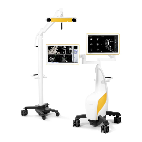
SYSTEM OVERVIEW SYSTEM OVERVIEW System Components Terminology The Curve Dual Navigation Station shall be referred to as “Curve system” in this user guide. Abbreviation UPS is used to abbreviate “uninterruptible power supply” in this manual. General Information The Curve system is a navigation platform used for image guided surgery, consisting of: •... - Page 20 System Components System Components ② ③ ① ④ ⑧ ⑤ ⑦ ⑥ Figure 1 Component ① Camera Cart Page 59 ② Camera Page 61 System User Guide Rev. 1.0 Curve Dual Navigation Station Ver. 1.2...
- Page 21 Monitor Cart Page 37 ⑤ EM Field Generator Positioning Arm Page 78 ⑥ EM Base Station Page 81 ⑦ EM Field Generator fixation plate Page 81 ⑧ EM Field Generator System User Guide Rev. 1.0 Curve Dual Navigation Station Ver. 1.2...
-
Page 22: System Setup
If camera’s infrared light interferes with other devices, reposition these devices and/or the camera so that the interference is resolved. The camera’s infrared light may interfere with other IR-based OR equipment, such as remote controls, pulse oximeters or IR-sensitive microscopes. System User Guide Rev. 1.0 Curve Dual Navigation Station Ver. 1.2... - Page 23 For EMC reasons, do not use system components adjacent to or stacked on other equipment. If it is unavoidable, verify that the Curve system operates normally. MR Safety The Curve system has not been tested in an MR environment. System User Guide Rev. 1.0 Curve Dual Navigation Station Ver. 1.2...
-
Page 24: Curve Em System Setup
The EM Tracking unit is not intended for use in an MR environment as the magnetic fields created by the EM Field Generator and MR scanner may influence each other. The Curve EM system has not been tested in an MR environment. System User Guide Rev. 1.0 Curve Dual Navigation Station Ver. 1.2... -
Page 25: Or Setups
Curve Setup - Example 2 Maximum extension of Monitor Cart: • Possibility to use second touchscreen, e.g., for unsterile software interaction • Maximum distance between patient and Monitor Cart body System User Guide Rev. 1.0 Curve Dual Navigation Station Ver. 1.2... - Page 26 System Setup Figure 3 Curve EM Setup Example For detailed setup descriptions please see the relevant Software User Guide. System User Guide Rev. 1.0 Curve Dual Navigation Station Ver. 1.2...
-
Page 27: Proper System Handling
SYSTEM OVERVIEW Proper System Handling Classification Curve Dual Navigation Station is classified as Class I Equipment according to IEC 60601-1 and must be tested accordingly. Classification Definition Refers to equipment classification regarding protection against electric shock. Class I Protective means are provided for metallic accessible parts or metallic internal parts, such as connection to PE (protective earth). - Page 28 Never touch the patient and any system parts or electrical interfaces at the same time, due to possible electrostatic discharge. Only connect the Curve Dual Navigation Station to a mains power supply with protective earth. Do not touch the electrical contacts of plugs.
- Page 29 NOTE: For more information on the operating and storage environment restrictions, see the Technical User Guide. Protection Covers Keep protection covers in a clean and dry place during surgery. System User Guide Rev. 1.0 Curve Dual Navigation Station Ver. 1.2...
-
Page 30: Inspections
Only Brainlab and/or authorized partners are allowed to repair the system and equipment. Risk of electrical shock: There are no user-serviceable parts in the Curve system. Do not remove any covers. All servicing and maintenance is to be carried out by trained Brainlab authorized technicians. -
Page 31: Annual Inspection
Annual Inspection Automatically performed by Brainlab. Contact Brainlab support for arrangement. Scope This inspection covers all components and functions as well as the items specified on the safety inspection form. System User Guide Rev. 1.0 Curve Dual Navigation Station Ver. 1.2... -
Page 32: Weekly And Monthly Inspections
The battery is now empty. • Fully charge battery by plugging in the system and switching on the mains power switch for two or more hours. System User Guide Rev. 1.0 Curve Dual Navigation Station Ver. 1.2... -
Page 33: Safety Inspection
• Informs Brainlab immediately in writing if the equipment is deemed unsafe Inspections by Brainlab Personnel • If a suitably qualified person is not available at the customer site, Brainlab support will perform this inspection for a set fee. • If you require a Brainlab support specialist, contact Brainlab support. -
Page 34: Malfunctions And Return Instructions
Attach a notice such as “DO NOT USE” to equipment to prevent it from being used inad- vertently. If you continue to use equipment that has been found to be defective during an inspection, you risk causing injury to the patient. System User Guide Rev. 1.0 Curve Dual Navigation Station Ver. 1.2... -
Page 35: Return Instructions
Brainlab KK Brainlab Ltd. RMA Dept. RMA Dept. Tamachi East Bldg. 2F Unit 2102, 21/F, The Hennessy 3-2-16 Shibaura, 256 Hennessy Road Minato-ku, Wan Chai Tokyo 108-0023 Hong Kong Japan System User Guide Rev. 1.0 Curve Dual Navigation Station Ver. 1.2... - Page 36 Malfunctions and Return Instructions System User Guide Rev. 1.0 Curve Dual Navigation Station Ver. 1.2...
-
Page 37: Monitor Cart
Technical User Guide ⑤ Cable storage hooks Page 58 ⑥ Adjustable monitor arm Page 44 ⑦ Touchscreen monitor Page 39 ⑧ Transport handle Page 117 ⑨ Power connection Page 56 System User Guide Rev. 1.0 Curve Dual Navigation Station Ver. 1.2... - Page 38 Back and Sound Panels ③ ② ④ ① Figure 6 Component ① Storage flap Page 58 ② Connection panel Page 48 ③ User panel Page 47 ④ Sound panel Page 51 System User Guide Rev. 1.0 Curve Dual Navigation Station Ver. 1.2...
-
Page 39: Cart Arms And Monitors
This can lead to temporary adverse effects to touchscreen functionality. In case fluids accidentally come in contact the display, dry them off as quickly as possible. Clean the touchscreens before use. NOTE: For more information, see Page 27. System User Guide Rev. 1.0 Curve Dual Navigation Station Ver. 1.2... - Page 40 Lower arm Do not attach or hang anything on the Monitor Cart arms. This may cause the cart to tip over. Do not lean on the Monitor Cart arms. System User Guide Rev. 1.0 Curve Dual Navigation Station Ver. 1.2...
-
Page 41: Range Of Motion
• The upper arm, has a restricted area of approximately 90° between the two arms to prevent the monitors from colliding, and to prevent possible user injury. Be aware that moving one arm may also move the other arm when the restricted area is reached. System User Guide Rev. 1.0 Curve Dual Navigation Station Ver. 1.2... - Page 42 Cart Arms and Monitors 165° 165° 90° 90° System User Guide Rev. 1.0 Curve Dual Navigation Station Ver. 1.2...
- Page 43 MONITOR CART Articulated Arm 165° 165° Figure 10 Monitor Rotation The monitors can be rotated 180° around the vertical display axis. 90° 90° Figure 11 System User Guide Rev. 1.0 Curve Dual Navigation Station Ver. 1.2...
-
Page 44: Positioning Monitors
Follow these standard procedures points when adjusting monitor position: • Move lower arm before upper arm. • Move inner joints first, working your way outward. • Follow the direction located on the parking position labels. System User Guide Rev. 1.0 Curve Dual Navigation Station Ver. 1.2... - Page 45 • Ensure that you will not injure anyone or damage equipment (e.g., if the second monitor is unintentionally moved). NOTE: For information on how to move Monitor Cart into transport position, see page 111. System User Guide Rev. 1.0 Curve Dual Navigation Station Ver. 1.2...
-
Page 46: Locking Monitors
When to Lock Ensure that all cart arm locks are secure: • Before using the touchscreens • Before docking the system • Before transportation System User Guide Rev. 1.0 Curve Dual Navigation Station Ver. 1.2... -
Page 47: Panels And System Ventilation
• DVD-R 4,7GB General • DVD-RW • DVD+R 8,5GB (Double Layer) • DVD+RW 4,7GB • DVD-RAM 4,7GB The following CD/DVD types can be written to: • DVD 4,7GB (DVD±R, DVD±RW, DVD-RAM) System User Guide Rev. 1.0 Curve Dual Navigation Station Ver. 1.2... - Page 48 1 GB network). There is a latch at the bottom which locks when plugged Intraoperative into the port. When removing the connector, press the Data latch, then pull plug out. System User Guide Rev. 1.0 Curve Dual Navigation Station Ver. 1.2...
- Page 49 LAN Connection Depending on the Brainlab application that is running on the system and the integration into the hospital network, connecting a system to the network offers patient data transfer, remote access, streaming and session sharing.
- Page 50 Network Environment Do not connect equipment to an unsecured network. Only operate the system in secured network environments. Otherwise, system function cannot be guaranteed due to possible malicious software infections. System User Guide Rev. 1.0 Curve Dual Navigation Station Ver. 1.2...
-
Page 51: Sound Panel
OR. If you use a mobile telephone to play MP3s, ensure that the telephone function has been turned off (airplane mode) to avoid performance issues. Do not connect or disconnect MP3 players when a surgery is in progress, as loud audio interference may occur. System User Guide Rev. 1.0 Curve Dual Navigation Station Ver. 1.2... - Page 52 Mute is activated. Sounds from the connected device are not audible. Stereo Jack Connector to connect an external passive music source via an audio cable (max. 3 m) with 3.5 mm stereo jack. System User Guide Rev. 1.0 Curve Dual Navigation Station Ver. 1.2...
-
Page 53: System Ventilation
Do not place system near or over a radiator or heat register or in direct sunlight. Place computer in a small enclosure only if sufficiently ventilated. System User Guide Rev. 1.0 Curve Dual Navigation Station Ver. 1.2... -
Page 54: Led Indications
Malfunction has been detected (see page 34). Contact Brainlab sup- Solid port. CD/DVD LED Color Status Explanation CD/DVD not being accessed or no CD/DVD inserted. Green Flashing CD/DVD is being accessed. System User Guide Rev. 1.0 Curve Dual Navigation Station Ver. 1.2... -
Page 55: Cabling
• Reduces differences of potential that can occur between medical electrical devices and other conductive parts of other objects during operation Before using the system, connect the potential equalization cable to the Monitor Cart and the corresponding wall outlet. System User Guide Rev. 1.0 Curve Dual Navigation Station Ver. 1.2... - Page 56 How to Connect Potential Equalization Cable ① ② Figure 17 Steps Plug potential equalization cable ② into potential equalization port of Monitor Cart ①. Plug potential equalization cable into an equivalent wall outlet. System User Guide Rev. 1.0 Curve Dual Navigation Station Ver. 1.2...
- Page 57 Always remove the mains power cable from the wall outlet first, before unplugging the cable from the system. Connecting Camera For information on connecting Camera Cart to the Monitor Cart using the camera cable, see page 62. System User Guide Rev. 1.0 Curve Dual Navigation Station Ver. 1.2...
-
Page 58: Cable Storage
(see page 38). Cable Hooks If a cable will remain connected to a cart, carefully bundle the cable together and hang it from the cable hooks (see page 37). System User Guide Rev. 1.0 Curve Dual Navigation Station Ver. 1.2... -
Page 59: Camera Cart
Transport handle with cable hooks Page 117 ③ Telescopic post Page 73 ④ Height adjustment handle Page 73 ⑤ Motor control unit Page 71 ⑥ Motorized joint Page 71 System User Guide Rev. 1.0 Curve Dual Navigation Station Ver. 1.2... - Page 60 Page 71 ③ Small wheels with single-sided brakes Page 105 ④ Camera cable connection Page 62 ⑤ Docking release mechanism Page 108 ⑥ On/off switch for camera motors Page 71 System User Guide Rev. 1.0 Curve Dual Navigation Station Ver. 1.2...
-
Page 61: Camera
The infrared LED array is located around the inner ring of the lenses. The infrared LED array is a “Class I LED product”. Do not directly look into the infrared LED array at a distance less than 15 cm. System User Guide Rev. 1.0 Curve Dual Navigation Station Ver. 1.2... -
Page 62: Cabling
Power up system by switching on the Monitor Cart. Disconnecting Camera Cable Figure 22 When disconnecting cables, do not twist the plug. Grasp the plug, rather than the cable, and pull it straight out. System User Guide Rev. 1.0 Curve Dual Navigation Station Ver. 1.2... - Page 63 CAMERA CART Store the camera cable on the hooks of the Camera Cart, even when using a Camera Cart with wireless camera communication. System User Guide Rev. 1.0 Curve Dual Navigation Station Ver. 1.2...
-
Page 64: Camera Use
Do not use any active wireless tool that is not specified by Brainlab. Do not use more than one active wireless tool at the same time. Communication with active wireless tools (such as Z-touch) can be established even when the camera is warming up. - Page 65 Warm-up Time Every time camera is powered on, it generally requires a warm-up time of two minutes. If camera is stored at low temperatures, warm-up time may be longer. System User Guide Rev. 1.0 Curve Dual Navigation Station Ver. 1.2...
-
Page 66: Range Of Motion
• Provides a rotation of 160° around the post 520 mm 160° Figure 23 Camera Cart Height The below minimum and maximum height values refer to the range of motion of the Camera Cart. System User Guide Rev. 1.0 Curve Dual Navigation Station Ver. 1.2... - Page 67 Camera Range of Motion The camera’s range of motion is as follows: • It can be pivoted 90° in one direction • It can be angled 30° upward and 90° downward System User Guide Rev. 1.0 Curve Dual Navigation Station Ver. 1.2...
- Page 68 Camera Use 90° 30° 90° Figure 25 System User Guide Rev. 1.0 Curve Dual Navigation Station Ver. 1.2...
-
Page 69: Operating Position
Safe Positioning Lock all four wheel brakes when Camera Cart is in operating position. Do not place Camera Cart or any of its parts over the patient. System User Guide Rev. 1.0 Curve Dual Navigation Station Ver. 1.2... -
Page 70: Adjusting Camera Position
Release camera handle. Camera will hold the position. NOTE: Contact Brainlab support if you are having difficulty adjusting the camera position. System Joints When adjusting the arm of the cart, be careful that fingers or other body parts do not accidentally become pinched in the joints of the system. - Page 71 Turn on switch for camera motors on the Camera Cart (see page 60). Use the controls in the software to adjust the camera: A beeping sound is audible to confirm movement. System User Guide Rev. 1.0 Curve Dual Navigation Station Ver. 1.2...
- Page 72 ① and contact Brainlab support. You can continue the surgery, using manual camera adjustment if necessary (see page 70). Tracking is not affected. System User Guide Rev. 1.0 Curve Dual Navigation Station Ver. 1.2...
- Page 73 While holding the camera handle ①, pull the rotation knob ② and rotate the camera 90°. Release the rotation knob, ensuring that it locks into position. Camera Cart Height Adjustment ① Figure 29 System User Guide Rev. 1.0 Curve Dual Navigation Station Ver. 1.2...
- Page 74 Ensure that all highly reflective items or sources of light do not obstruct the camera’s view. Artifacts caused by reflections can reduce accuracy, especially during registration. System User Guide Rev. 1.0 Curve Dual Navigation Station Ver. 1.2...
-
Page 75: Leds And Acoustic Signals
• Contact Brainlab support (even if navigation is still possi- Error LED ③ ble). • Camera defect. Solid amber • Contact Brainlab support (even if navigation is still possi- ble). System User Guide Rev. 1.0 Curve Dual Navigation Station Ver. 1.2... - Page 76 LEDs and Acoustic Signals NOTE: If there is no signal from the power LED or status LED, contact Brainlab support (even if navigation is still possible). Acoustic Signals Camera emits two beeps when: • Reset is performed • Power is applied to system •...
-
Page 77: Em Tracking Unit
Do not attempt to dismantle or assemble any components of the EM Tracking Unit. To maintain tracking accuracy over the defined lifetime it is necessary to perform an accuracy test of the EM Tracking Unit every 3 years by Brainlab authorized personnel. Do not sterilize the EM Tracking Device or its components. - Page 78 Figure 32 Component ① Power connection ② EM instrument LEDs ③ Power LED ④ EM instrument ports ⑤ Tool extension port ⑥ Navigation system port ⑦ EM Field Generator port System User Guide Rev. 1.0 Curve Dual Navigation Station Ver. 1.2...
-
Page 79: Em Tracking Unit Setup
Unit are not single-fault safe in terms of functional safety and thus may fail during operation. Do not drop the EM Field Generator or subject it to impacts. Physical damage to the Field Generator may alter the calibration. Inform Brainlab Support in case of the EM Field Generator was subjected to an impact. Disturbances A tracked instrument having a motorized element (e.g. -
Page 80: Setting Up Em Tracking Unit
EM Tracking Unit Setup 5.2.2 Setting Up EM Tracking Unit EM Tracking Unit Transport Cases ① ② ③ Figure 33 Component ① Unsterile instrument case ② Bottom layer ③ Top layer System User Guide Rev. 1.0 Curve Dual Navigation Station Ver. 1.2... - Page 81 Figure 34 Component ① Release mechanism ② Fixation interface ③ EM Field Generator fixation plate ④ Velcro strap attachment ⑤ Velcro strap ⑥ EM Field Generator ⑦ Fixation piece System User Guide Rev. 1.0 Curve Dual Navigation Station Ver. 1.2...
- Page 82 Remove unsterile instrument case from the transport case, placing it on an unsterile sur- face. Remove the top layer of the transport case, placing it where it will remain clean and dry. System User Guide Rev. 1.0 Curve Dual Navigation Station Ver. 1.2...
- Page 83 Replace top layer of transport case and store the case out of the way, where it will remain clean and dry. Cabling Precautions Only use the power cables provided by Brainlab to power the EM Tracking Unit. Do not extend power cables. Risk of electrical shock: Do not touch cable plugs when Monitor Cart is turned on.
-
Page 84: Connecting Em Tracking Unit To Monitor Cart
Turning the EM Tracking Unit On When the EM Tracking Unitand Monitor Cart are connected, the EM Tracking Unit is powered on as soon as the Monitor Cart is turned on (see page 96). System User Guide Rev. 1.0 Curve Dual Navigation Station Ver. 1.2... - Page 85 Always disconnect the EM power cable from the EM Tracking Unit before connecting or disconnecting the EM data cable of the EM Field Generator cable. System User Guide Rev. 1.0 Curve Dual Navigation Station Ver. 1.2...
-
Page 86: Connecting Em Instruments
When the EM instrument is recognized by the software as a valid, the LED color changes from amber to green. NOTE: Available EM instruments are described in the corresponding Instrument User Guide. System User Guide Rev. 1.0 Curve Dual Navigation Station Ver. 1.2... -
Page 87: Using The Em Tracking Unit
Do not attempt to disassemble or assemble any components of the EM Tracking Unit. Altering the EM Tracking Unit or using it outside of its intended use may result in severe harm to the patient, user or third party. System User Guide Rev. 1.0 Curve Dual Navigation Station Ver. 1.2... -
Page 88: Positioning Components
The EM Field Generator can be positioned on either side of the patient’s head. Select a setup in which the EM Field Generator does not interfere with the surgeon’s position. Use an appropriate head rest for the patient. Figure 40 System User Guide Rev. 1.0 Curve Dual Navigation Station Ver. 1.2... - Page 89 The EM Base Station uses two fans to cool the electronic components inside. Do not block the ventilation openings of the EM Base Station. ① ③ ④ ② Figure 41 System User Guide Rev. 1.0 Curve Dual Navigation Station Ver. 1.2...
- Page 90 OR table may move components and pull on attached cables. Do not move the EM Field Generator while tracking an instrument or reference, as this may affect navigation accuracy. System User Guide Rev. 1.0 Curve Dual Navigation Station Ver. 1.2...
-
Page 91: Positioning Patient
100 and 350 mm from the EM Field Generator front. ③ ② ④ ① ⑤ Figure 43 Component ① ② Side ③ Back ④ Available navigation volume System User Guide Rev. 1.0 Curve Dual Navigation Station Ver. 1.2... - Page 92 Use an appropriate head rest for the patient in order to set the head on a level where the face of the EM Field Generator approximately covers the area of interest, including EM instruments. Figure 44 System User Guide Rev. 1.0 Curve Dual Navigation Station Ver. 1.2...
-
Page 93: Leds And Acoustic Signals
• Contact Brainlab support if an EM instrument is connect- ed, the Monitor Cart and the EM Base Station are pow- ered on, but the LED remains off. System User Guide Rev. 1.0 Curve Dual Navigation Station Ver. 1.2... - Page 94 LEDs and Acoustic Signals Acoustic Signals The EM Tracking Unit emits two beeps when: • Reset is performed. • Power is applied to system. • Connection is made to Brainlab software. System User Guide Rev. 1.0 Curve Dual Navigation Station Ver. 1.2...
-
Page 95: Using The System
Power Supply Operate system using the power source indicated on type plate. If you are unsure of type of power available, consult Brainlab support or your local power company. Using the wrong power source could seriously damage system. Check voltage setting before plugging mains power cable into wall outlet. -
Page 96: Turning On System
The system starts automatically. Waiting Period If system has been turned off, wait at least 60 seconds before turning it on again. Otherwise, high input current may trip the circuit breaker. System User Guide Rev. 1.0 Curve Dual Navigation Station Ver. 1.2... -
Page 97: System Shutdown
Should a power failure occur, be aware that the UPS only keeps the system running for maximum five minutes. Apply mains power or shut down the system to avoid irreversible loss of data. System User Guide Rev. 1.0 Curve Dual Navigation Station Ver. 1.2... - Page 98 System Shutdown Loss of Data Failure to follow system shutdown procedure prior to disconnecting power may result in irreversible loss of data. System User Guide Rev. 1.0 Curve Dual Navigation Station Ver. 1.2...
-
Page 99: Sterile Use
Do not use the Sterile Camera Handle Drape if it rips or becomes damaged during mounting. How to Remove Packaging Figure 47 Steps Have a second person open and peel back packaging. Remove Sterile Camera Handle Drape from packaging. System User Guide Rev. 1.0 Curve Dual Navigation Station Ver. 1.2... - Page 100 To remove Sterile Camera Handle Drape ② from the camera handle ①, pull the drape off. NOTE: Avoid coming in contact with the camera cable ③ when adjusting the camera sterilely. Verify that Sterile Camera Handle Drape has snapped properly into place. System User Guide Rev. 1.0 Curve Dual Navigation Station Ver. 1.2...
-
Page 101: Sterile Monitor Drape
Sterile Monitor Drape General Information The monitor may be draped using the sterile Monitor Drape provided by Brainlab. The drape allows you to intraoperatively access all software functions and position monitor during surgery without compromising the sterile field. The 27” Display Drape (19903-40) is intended to be used with the Curve display. - Page 102 Repeat for the second adhesive strip on the lower part of the drape. Draped Curve Figure 49 Operating Draped Touchscreen Do not touch drape with sharp tools. To keep sterile field, only touch touchscreen and monitor housing where covered by drape. System User Guide Rev. 1.0 Curve Dual Navigation Station Ver. 1.2...
- Page 103 USING THE SYSTEM Disposal Dispose of the drape after use. System User Guide Rev. 1.0 Curve Dual Navigation Station Ver. 1.2...
- Page 104 Sterile Use System User Guide Rev. 1.0 Curve Dual Navigation Station Ver. 1.2...
-
Page 105: Transport
Each wheel has an individual foot brake so that it can be easily transported and securely parked. Fully lock all brakes when the carts are stored, parked or in operation. Before Transport Release all brakes before moving the system. System User Guide Rev. 1.0 Curve Dual Navigation Station Ver. 1.2... -
Page 106: Monitor Cart Brakes
To lock, push the brake pedal ③ down with your foot until it snaps into locked position ①. To unlock, push brake pedal ③ up until it snaps into unlocked position ②. System User Guide Rev. 1.0 Curve Dual Navigation Station Ver. 1.2... -
Page 107: Camera Cart Brakes
To lock, push the brake pedal ③ down with your foot until it snaps into locked position ①. To unlock, push brake pedal ③ up until it snaps into unlocked position ②. System User Guide Rev. 1.0 Curve Dual Navigation Station Ver. 1.2... -
Page 108: Docking Camera And Monitor Carts
Disconnect camera from Monitor Cart. Clean touchscreens before applying the monitor protection covers (see page 127). Monitor Cover (Front) Figure 52 System User Guide Rev. 1.0 Curve Dual Navigation Station Ver. 1.2... - Page 109 Secure camera to the camera post using the protection cover Velcro strap ②. NOTE: To complete this step, the Camera Cart must be in transport/storage position (see starting at page 113). System User Guide Rev. 1.0 Curve Dual Navigation Station Ver. 1.2...
- Page 110 Camera must be secured with the protection cover strap to prevent unintentional movement during transport. To avoid overheating, ensure that the camera has been turned off for at least five minutes before applying the protection cover. System User Guide Rev. 1.0 Curve Dual Navigation Station Ver. 1.2...
-
Page 111: Transport And Parking Position
Monitor Cart post. NOTE: Be aware that there is a fixation that causes the upper arm to move when the angle between both arms is 90°. System User Guide Rev. 1.0 Curve Dual Navigation Station Ver. 1.2... - Page 112 90° in the opposite direction and the parking la- bels will line up. The Monitor Cart is then in final position. System User Guide Rev. 1.0 Curve Dual Navigation Station Ver. 1.2...
- Page 113 NOTE: If the post is in a low position, the parking label may be covered. Use one or two hands to move the post up or down until the parking label aligns with the fixed section of the post. System User Guide Rev. 1.0 Curve Dual Navigation Station Ver. 1.2...
- Page 114 (when standing behind the cart). Use the camera protection cover to secure the camera and fix the position. An extended camera arm could hit persons while the post is being moved. System User Guide Rev. 1.0 Curve Dual Navigation Station Ver. 1.2...
-
Page 115: Docking And Undocking Procedure
NOTE: It is recommended to always move the Camera Cart into the Monitor Cart and not the other way around. Do not try attempt to dock anything other than the Camera Cart to the Monitor Cart. Final Docked Position Figure 57 System User Guide Rev. 1.0 Curve Dual Navigation Station Ver. 1.2... - Page 116 “undocked” position ②. Re-dock the carts. How to Undock Steps Push docking pedal down ② to open locking mechanism. Pull Camera Cart away from Monitor Cart. System User Guide Rev. 1.0 Curve Dual Navigation Station Ver. 1.2...
-
Page 117: Transporting The System
The system should be moved by one person. If assistance from a second person is required, ensure during transport that fingers or other body parts are not pinched in the joints of the system. System User Guide Rev. 1.0 Curve Dual Navigation Station Ver. 1.2... - Page 118 Do not move the system by pulling on the cables. System transportation should be supervised by at least one person to avoid collisions with other equipment, structures or people. System User Guide Rev. 1.0 Curve Dual Navigation Station Ver. 1.2...
-
Page 119: Proper Transport Procedure
NOTE: Procedure is applicable for depth variations of 8 mm-20 mm. Steps Keeping the carts in transport position, undock Monitor and Camera Carts (see page 115) so they can be moved individually. System User Guide Rev. 1.0 Curve Dual Navigation Station Ver. 1.2... - Page 120 Technical User Guide. Failure to do so may cause the camera to lose its calibration accuracy. After transporting, wait until the system has adjusted to room temperature before operating. System User Guide Rev. 1.0 Curve Dual Navigation Station Ver. 1.2...
-
Page 121: Parking And Storage
When the system is not in use, always keep the carts in the secure transport and parking position (see page 111). Safe Parking The system may only be parked on level surfaces. Ensure that all wheel brakes are locked when parked. System User Guide Rev. 1.0 Curve Dual Navigation Station Ver. 1.2... -
Page 122: Storage
When storing the system, always keep the carts docked together in the secure transport and parking position (see page 111). Environmental Requirements See the Technical User Guide for detailed environmental restrictions. System User Guide Rev. 1.0 Curve Dual Navigation Station Ver. 1.2... -
Page 123: Transporting The Em Tracking Unit Using Transport Cases
Disconnect the EM Field Generator cable and both connectors of the EM cable from EM Base Station. Store EM Base Station in the bottom layer of the transport case ④. System User Guide Rev. 1.0 Curve Dual Navigation Station Ver. 1.2... - Page 124 Disconnect the EM Field Generator cable and both connectors of the EM cable from EM Base Station. Store EM Base Station in the bottom layer of the transport case ④. System User Guide Rev. 1.0 Curve Dual Navigation Station Ver. 1.2...
- Page 125 Store the EM Field Generator Positioning Arm in the top layer of the transport case ⑨. Put the unsterile instruments into the unsterile instrument case ⑪. Place the unsterile instrument case ⑪ into the transport case⑩. System User Guide Rev. 1.0 Curve Dual Navigation Station Ver. 1.2...
-
Page 126: Long Term Storage
Start system and verify correct function before using it for surgery (see page 95). Disposal If you do not intend to use the system again, please follow the disposal information on page 8. System User Guide Rev. 1.0 Curve Dual Navigation Station Ver. 1.2... -
Page 127: Cleaning
Ensure that liquid does not enter the Curve components, as this could damage the component and/or the electronics. Use only a moist cloth for cleaning. Other methods could allow liquids to enter the system and cause damage. System User Guide Rev. 1.0 Curve Dual Navigation Station Ver. 1.2... - Page 128 Antiseptica Kombi - Flächendesinfektion NOTE: Use only surface disinfectants released in your specific market. NOTE: Surface disinfectants may leave a residue. This can be easily removed using a dry cloth. System User Guide Rev. 1.0 Curve Dual Navigation Station Ver. 1.2...
-
Page 129: Curve System
Gently wipe surface in one direction only, by pulling brush across surface. Gently wipe surface of illuminator filters and lenses with disinfectant wipes containing 70% Isopropanol or Meliseptol. Follow disinfectant manufacturer’s recommendations. System User Guide Rev. 1.0 Curve Dual Navigation Station Ver. 1.2... - Page 130 Do not sterilize the camera. Camera Cleaning Intervals As frequency of cleaning depends on how frequently the camera is used, Brainlab cannot give general recommendation on cleaning intervals. This is within the user’s responsibility. Regularly inspect illuminator filter and lenses for cleanness, however only clean them when necessary.
-
Page 131: Protection Cover For Monitors
NOTE: If a soiled cover cannot be sufficiently cleaned using the above steps, exchange the cover for a new one. Do not wash, soak, iron or sterilize protection covers. Do Not Use • Acid solvents • Caustic solvents with pH value higher than 9.5 System User Guide Rev. 1.0 Curve Dual Navigation Station Ver. 1.2... -
Page 132: Protection Cover For Camera
Do not wash, soak, iron, disinfect or sterilize protection covers. Do Not Use • Acid solvents • Caustic solvents with pH value higher than 9.5 System User Guide Rev. 1.0 Curve Dual Navigation Station Ver. 1.2... -
Page 133: Transport Cases
Clean and disinfect only the outside surfaces of the transport cases. Do not clean or disin- fect surfaces on the inside of the cases. Allow the transport cases to fully dry before inserting the system. NOTE: After drying, surface disinfectants may leave stains. System User Guide Rev. 1.0 Curve Dual Navigation Station Ver. 1.2... - Page 134 Cleaning Instructions System User Guide Rev. 1.0 Curve Dual Navigation Station Ver. 1.2...
-
Page 135: Index
131,132 weekly..................32 compatibility instruments disinfectants................128 EM tracking................86 connecting interference EM tracking unit..............84 electromagnetic fields.............24 IR light..................22 radio..................29 disinfectants................128 disposal instructions..............8 docking pedal................116 System User Guide Rev. 1.0 Curve Dual Navigation Station Ver. 1.2... - Page 136 35 rotation of camera..............67,73 safety inspection.................33 shutdown..................97 sterile camera handle drape............99 sterile use................... 99 System User Guide Rev. 1.0 Curve Dual Navigation Station Ver. 1.2...
- Page 138 Art-No. 60915-52EN *60915-52EN*...
Need help?
Do you have a question about the Curve Dual Navigation Station and is the answer not in the manual?
Questions and answers