
Related Manuals for Conductix-Wampfler SingleFlexLine Program 0815


Summary of Contents for Conductix-Wampfler SingleFlexLine Program 0815
- Page 1 Operating Instructions Single-pole conductor-rail system SingleFlexLine Program 0815 Order Number: 0815xx-… BAL0815-0002d-US www.conductix.us translated document page 1 of 94...
-
Page 2: Table Of Contents
Operating Instructions Single-pole conductor-rail system SingleFlexLine Program 0815 Contents General notes ..................................... 5 About this document ..............................5 Limitation of liability ..............................5 Copyright ..................................6 Spare parts .................................. 6 Material defects ................................6 Technical support ................................ 6 Safety instructions ..................................7 Explanation of symbols .............................. - Page 3 Operating Instructions Single-pole conductor-rail system SingleFlexLine Program 0815 3.2.3 Tolerances ................................. 19 Unsuitable environmental conditions ......................... 20 Product description and method of functioning ......................... 21 Brief description ................................. 21 Interfaces ................................... 24 Description of the components ..........................24 Accessories ................................28 4.4.1...
- Page 4 Operating Instructions Single-pole conductor-rail system SingleFlexLine Program 0815 7.2.1 Inspection list ................................66 7.2.2 Initial start-up of the conductor-rail system ........................ 67 Operation ....................................68 Safety ..................................68 Normal operation ............................... 70 Stopping the system ..............................71 Continuing operation ..............................71 Perform regular maintenance and servicing ......................
-
Page 5: General Notes
Operating Instructions Single-pole conductor-rail system SingleFlexLine Program 0815 1 General notes 1.1 About this document The information provided in this manual is designed to enable the conductor-rail system to be used safely and efficiently. This document forms part of the conductor-rail system and must be kept accessible to personnel at all times and stored right by the device. -
Page 6: Copyright
Operating Instructions Single-pole conductor-rail system SingleFlexLine Program 0815 1.3 Copyright This document is subject to copyright, and is exclusively intended for internal use by customers. Provision of the operating instructions to third parties, reproductions in any form – even in part – as well as the reuse and/or disclosure of their content are not permitted without the written approval of the manufacturer, except for the customer's internal use. -
Page 7: Safety Instructions
Operating Instructions Single-pole conductor-rail system SingleFlexLine Program 0815 2 Safety instructions 2.1 Explanation of symbols Safety and hazard information is identified in these operating instruction by symbols. Safety instructions are introduced by signal words that indicate the scale of the hazard. Always observe safety and hazard instructions, and work carefully to avoid accidents, bodily injury and damage to property! ... -
Page 8: Personnel Requirements
Operating Instructions Single-pole conductor-rail system SingleFlexLine Program 0815 2.2 Personnel requirements 2.2.1 Qualifications Persons who are not adequately trained are at risk of injury! Improper use can result in serious injury to persons and property. → All activities must only be performed by qualified personnel. -
Page 9: Unauthorized Personnel
Operating Instructions Single-pole conductor-rail system SingleFlexLine Program 0815 2.2.2 Unauthorized personnel Danger due to unauthorized personnel! Unauthorized persons who do not meet the requirements described here are not ac- quainted with the dangers in the working area. WARNING! → Keep unauthorized personnel out of the working area →... -
Page 10: Intended Use
Operating Instructions Single-pole conductor-rail system SingleFlexLine Program 0815 To be worn for spe- Special personal protective equipment must be used when carrying out certain tasks. The need cial tasks for such personal protective equipment will be detailed in the individual chapters of this manual. -
Page 11: Use Other Than The Intended Use
Operating Instructions Single-pole conductor-rail system SingleFlexLine Program 0815 The following technical requirements must always be strictly observed for the installation: The maximum permissible traversing speed of the consumer is up to 600 m/min depending on the system The conductor-rail must only be fitted horizontally ... -
Page 12: Protective Measures To Be Taken By The Operator/User
Operating Instructions Single-pole conductor-rail system SingleFlexLine Program 0815 2.6 Protective measures to be taken by the operator/user The device is designed for use in an industrial setting. The operator of the device is therefore subject to compliance with the relevant legal obligations concerning workplace safety. -
Page 13: Specific Hazards
Operating Instructions Single-pole conductor-rail system SingleFlexLine Program 0815 2.8 Specific hazards The following chapter lists residual risks, which were determined on the basis of a risk assessment. → Follow the safety instructions and the warnings in these operating instructions in order to reduce health hazards and avoid dan- gerous situations. -
Page 14: Mechanical Hazards And Sources Of Danger
Operating Instructions Single-pole conductor-rail system SingleFlexLine Program 0815 Fire hazard due to overload or sparking! A fire hazard can occur due to overloads of the cable, electrical arcing, short circuits or the generation of sparks. Sparking can occur in poorly serviced, contaminated conductor-rails or if DANGER! installation does not comply with the required tolerances. -
Page 15: Danger Due To Dust And Vapors
Operating Instructions Single-pole conductor-rail system SingleFlexLine Program 0815 2.8.3 Danger due to dust and vapors Danger of sensitization, irritation of the mucous membranes, and respiratory diseases due to dust! Dust from the collector brushes collects in the conductor-rails and the guide pro- WARNING! file. -
Page 16: Hazards Arising From The Operating Environment
→ Use in chemical works, galvanizing plants, electroplating plants, composting plants or in warehouses or installations where chemical substances (e.g., aromatics, benzene) are stored or processed must be checked in advance by Conductix-Wampfler The resistance of plastic parts is critical in contact with oils, greases or various cleaning agents. -
Page 17: Conduct In The Event Of Accidents And Malfunctions
Operating Instructions Single-pole conductor-rail system SingleFlexLine Program 0815 Risk due to energy storage! If consumers with energy storage are supplied by the conductor-rail, these must be disconnected from the conductor-rail or the energy-storage system must be discharged according to the manu- DANGER! facturer’s specifications before starting work and system checked for the absence of a voltage. -
Page 18: Technical Specifications
Operating Instructions Single-pole conductor-rail system SingleFlexLine Program 0815 3 Technical specifications 3.1 Electrical Rated current for the overall system 10–54 A as an overall system with expansion elements; (conductor- rails: 10–100 A) Rated current for current Single current collector Pure carbon: max. 16 A collectors* Copper–graphite: max. -
Page 19: Installation Orientation
The conductor-rail must be installed within the following tolerances. Conductix-Wampfler does not accept any responsibility for the conductor-rail's correct functioning if these tolerances are not observed. In such a case, Conductix-Wampfler does not accept any liability for problems that arise if the conductor-rail system is not functioning correctly. -
Page 20: Unsuitable Environmental Conditions
Operating Instructions Single-pole conductor-rail system SingleFlexLine Program 0815 3.3 Unsuitable environmental conditions The conductor-rail must not be installed and not be operated under these environmental conditions (see also Chapter 2.5, Chapter 2.8.4 and Chapter 3): In environments containing chemical substances or gases that can potentially permanently damage the conductor-rail's materials ... -
Page 21: Product Description And Method Of Functioning
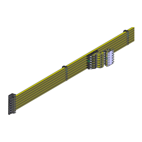
Operating Instructions Single-pole conductor-rail system SingleFlexLine Program 0815 4 Product description and method of functioning 4.1 Brief description Single-pole insulated conductor-rails consist of individual conductor-rails firmly fixed on a guideway. One or more current collectors fastened to one or more mobile consumers engage with the conductor-rails with their current-collecting heads. The mobile consumers move along the guideway in a linear, track-guided manner. - Page 22 Operating Instructions Single-pole conductor-rail system SingleFlexLine Program 0815 Fig. 2: System layout *The installation spacing depends on the current-collector type (65 mm, 80 mm, 92 mm) Item Name End cap Connectors Hanger clamp Power feed Air gap insulation section with expansion travel Transition caps/”long”...
- Page 23 Operating Instructions Single-pole conductor-rail system SingleFlexLine Program 0815 Use of bends in horizontal and vertical curves Engagement direction of the current collector Vertical (from below) Horizontal (from the side) Horizontal bend Internal/external bend suspension interval: 400 mm suspension interval: 250 mm Horizontal curve bend radius: 1000 mm to ∞...
-
Page 24: Interfaces
Operating Instructions Single-pole conductor-rail system SingleFlexLine Program 0815 4.2 Interfaces All details are in the catalog, the installation instructions and possibly in the system-specific lay- out. Mechanical interfaces: The current collector must be fastened to the mobile consumer of the machine. The manufacturer/operator of the machine/system ... - Page 25 Operating Instructions Single-pole conductor-rail system SingleFlexLine Program 0815 variant is used with error prevention. For PE rails plus plus the insulation is opened wider for a broader PE brush. plus The wider PE collector brushes mostly prevent (without plus use of force or crash) the dip of the collector brush in a phase rail.
- Page 26 Operating Instructions Single-pole conductor-rail system SingleFlexLine Program 0815 Connectors For mechanically and electrically connecting the individual rail sections (plug or quick-screw technology). The connect- ors are easily accessible from the front of the conductor-rail. Each connection point is protected against contact by a plas- tic connector cap.
- Page 27 Operating Instructions Single-pole conductor-rail system SingleFlexLine Program 0815 Expansion element The expansion element is used to compensate for the ther- mal expansion of the installation structure/EMS rail and con- ductor-rail. Building expansion points must be taken into account in the installation of the conductor-rail system.
-
Page 28: Accessories
Operating Instructions Single-pole conductor-rail system SingleFlexLine Program 0815 Current collector Current collector as a sliding electrical connection between con- ductor-rail and the moving consumer. Usually designed as a multiple-pole unit. Fig. 15: Current collectors and current-collector unit (for older exist- ing systems) Fig. -
Page 29: Tools And Materials
Operating Instructions Single-pole conductor-rail system SingleFlexLine Program 0815 Suction head/conductor-rail-cleaning unit Various solutions are available for removing loose buildup and deposits on conductor-rails and EMS rails. Technical design and application details are available on request. Fig. 18: Rail cleaner 4.4.1... -
Page 30: Transport, Packaging And Storage
Operating Instructions Single-pole conductor-rail system SingleFlexLine Program 0815 5 Transport, packaging and storage 5.1 Safety Required protective equipment: Risk of death due to suspended loads! Falling parts or uncontrolled swinging loads can lead to severe injury or even death. → Never walk under suspended loads. -
Page 31: Transport
Operating Instructions Single-pole conductor-rail system SingleFlexLine Program 0815 Risk of injury from cuts and cutting! Cuts and amputations can occur: on packaging material (such as cartons, tapes, etc.) DANGER! on sharp edges of the conductor-rail → Use personal protective equipment! -
Page 32: Packaging
Operating Instructions Single-pole conductor-rail system SingleFlexLine Program 0815 5.3 Packaging The individually packaged parts have been packed in accordance with the anticipated transport conditions. Only environmentally friendly materials have been used for packaging. The packaging is designed to protect the individual components from transport damage, corrosion and other damage until installation. -
Page 33: Assembly
Operating Instructions Single-pole conductor-rail system SingleFlexLine Program 0815 6 Assembly 6.1 Safety Installation and initial commissioning may only be carried out by specially trained technicians. Required protective equipment: Risk of death due to suspended loads! Falling loads can lead to severe injuries or even death. - Page 34 Operating Instructions Single-pole conductor-rail system SingleFlexLine Program 0815 Risk of injury by crushing skin and limbs! There is a danger of crushing of skin and limbs due to: Spring force/gravity (stored energy) DANGER! Current collector (spring force) during installation, dismantling and maintenance ...
- Page 35 Operating Instructions Single-pole conductor-rail system SingleFlexLine Program 0815 Risk of puncture wounds and cuts! The packaging material can contain sharp objects such as nails and wood splinters that can cause injury to limbs. CAUTION! → Use personal protective equipment! → Cordon off the work area! →...
-
Page 36: Providing Additional Protection Against Accidental Contact At The Conductor-Rail End
Operating Instructions Single-pole conductor-rail system SingleFlexLine Program 0815 To the side of the conductor-rail there must, a clearance of at least 4 mm from metal components must be maintained (see Fig. 19) to prevent mechanical collisions and guarantee sufficient electrical insulation distances! ATTENTION! Fig. -
Page 37: Procedure
Operating Instructions Single-pole conductor-rail system SingleFlexLine Program 0815 6.3 Procedure 6.3.1 Required tools Standard tool: Measuring tape Calipers Scribe Allen key (3 mm) Cutting tool (e.g. cordless angle grinder) For producing short lengths File for deburring cut edges after trimming ... - Page 38 Operating Instructions Single-pole conductor-rail system SingleFlexLine Program 0815 Sharp edges and burrs result in increased wear of the collector brushes! A sharp edge and/or burr can rapidly wear away the carbon of the collector brushes. → Deburr the sawed end with a smooth file CAUTION! →...
- Page 39 Operating Instructions Single-pole conductor-rail system SingleFlexLine Program 0815 Fig. 22: PE rail with end machining (plastic bar removed) Fig. 23: Rear side of the rail plus The PE rail has a plastic bar in the insulating profile! plus → Remove the plastic bar at each end using a print cutter or other suitable tool so that the connector...
-
Page 40: Making A Bend In The Conductor Rail
Operating Instructions Single-pole conductor-rail system SingleFlexLine Program 0815 6.3.2.2 Making a bend in the conductor rail Read and respect the additional operating instructions! You can find additional information on the making a bend in a conductor rail in BAL0800-0004. Conductor-rail bends can be fabricated in the factory or on site. They are prepared using the bending device 081091. For large installations, electrically driven bending devices available upon request. - Page 41 Operating Instructions Single-pole conductor-rail system SingleFlexLine Program 0815 To avoid undesired deformations of the conductor-rail, the plastic insert supplied must be inserted in the slit in the contact surface before forming the bend and the removed once the bending process is complete.
- Page 42 Operating Instructions Single-pole conductor-rail system SingleFlexLine Program 0815 → Using the setting spindle, move the upper bending roller upwards until the rail section can be inserted into the cutout provided in the bending device. → Adjust the position of the bending roller downwards and move the rail section back and forth.
-
Page 43: Assembling The Conductor-Rail System
Operating Instructions Single-pole conductor-rail system SingleFlexLine Program 0815 6.3.3 Assembling the conductor-rail system To the side of the conductor-rail there must, a clearance of at least 4 mm from metal components must be maintained (see Fig. 29) to prevent mechanical collisions and guarantee sufficient electri-... -
Page 44: Setting The Hanger Clamps
Operating Instructions Single-pole conductor-rail system SingleFlexLine Program 0815 6.3.3.1 Setting the hanger clamps The following must be observed when setting the hanger clamps: → Set the hanger clamps at intervals of approx. 500 mm and at intervals of 400 mm and 250 mm respectively for internal and external horizontal bends. - Page 45 Operating Instructions Single-pole conductor-rail system SingleFlexLine Program 0815 Item Name Guideway rail Hanger clamp Fig. 32: Comparison of correctly and incorrectly engaged rail Fig. 33: Clip the hanger clamp into the conductor-rail Standard hanger clamp for screwing on: To fasten the standard hanger clamps, drill holes must be made in the EMS rail. The drilling jig for support profile height 180 mm (Material-Nr.
- Page 46 Operating Instructions Single-pole conductor-rail system SingleFlexLine Program 0815 Fig. 34: Drilling jig for hanger clamp Fig. 35: Drill hole distance of the female connectors Fig. 36: Drill hole distance of the female connectors (detail C) code (“click“ “scan“), watch animation Mounting Hanger Clamps (clip-in, screwable and turnable).
-
Page 47: Installing Conductor-Rail And Connectors
Operating Instructions Single-pole conductor-rail system SingleFlexLine Program 0815 6.3.3.2 Installing conductor-rail and connectors → After installation of the hanger clamps and preparations of the transitions and power feed points, push the conductor-rails into the hanger clamps, Make sure that the conductor-rails engage correctly and the hanger clamp covers the insulation above and below (see Fig. - Page 48 Operating Instructions Single-pole conductor-rail system SingleFlexLine Program 0815 Fig. 38: Push the rails onto the connector Fig. 39: Correct position of the clamp Fig. 40: Incorrect position of the clamp Tighten the connector with a 3-mm hex screwdriver to 2 Nm.
- Page 49 Operating Instructions Single-pole conductor-rail system SingleFlexLine Program 0815 Fig. 43: Support profile with a conductor-rail installed Conductor-rails can become deformed when bent! → Check conductor-rail bends for the correct profile, because conductor-rails can deform when bent in the area of the insulation CAUTION! →...
- Page 50 Operating Instructions Single-pole conductor-rail system SingleFlexLine Program 0815 During installation, it can happen that a conductor-rail has to be taken out of a hanger clamp again. There is a dismantling tool for this (order no.: 081092). This is used to dismantle the conductor-rail fixed in the hanger clamp and end caps bars (see Fig.
-
Page 51: Installing A Section Power Feed
Operating Instructions Single-pole conductor-rail system SingleFlexLine Program 0815 6.3.3.3 Installing a section power feed → The section power feed is installed instead of a connector. Here, a different clamping part and a power feed cap with room for a connecting cable to run out of it are used. - Page 52 Operating Instructions Single-pole conductor-rail system SingleFlexLine Program 0815 By using a section power feed, power can be supplied at any connection point in the route. The connection is made using a crimping cable lug of 1,5 mm to 10 mm max.
-
Page 53: Installing End Caps And End Power Feeds
Operating Instructions Single-pole conductor-rail system SingleFlexLine Program 0815 6.3.3.4 Installing end caps and end power feeds Drill the guideway profile in accordance with the layout and allocation plan. The use of a drilling jig is recommended in order to ensure the exact position of the end caps. - Page 54 Operating Instructions Single-pole conductor-rail system SingleFlexLine Program 0815 For end power feeds, the power can be supplied at the end of the route. An end power feed consists of an end cap with a power feed clamping unit. The connection is made using a crimping cable lug with a conductor cross section of 1.5 mm to 6 mm .
-
Page 55: Mounting The Fixed Point
Operating Instructions Single-pole conductor-rail system SingleFlexLine Program 0815 code (“click“ “scan“), watch animation Mounting End Cap for End Cap Base and Clipping Rail. 6.3.3.5 Mounting the fixed point A fixed point consists of a hanger clamp and 2 fixed point clamps per pole. The positions of the fixed points are determined when planning the system. - Page 56 Operating Instructions Single-pole conductor-rail system SingleFlexLine Program 0815 Fig. 64: Insert the engagement cam into the hole Fig. 65: Fully assembled fixed point Item Name Engagement cam Fixed-point cap Hanger clamp Track profile Screw Additional fixing of the hanger clamp is required for clip-in hanger clamps! For clip-in hanger clamps, the hanger clamp that is to be used as the fixed point must be addition- ally secured to the support profile/building structure with a screw.
-
Page 57: Installing The Current Collector
Operating Instructions Single-pole conductor-rail system SingleFlexLine Program 0815 code (“click“ “scan“), watch animation Mounting Fixed Point. 6.3.4 Installing the current collector Different current collectors are used for existing and new systems: Tolerances in the X-axis and Y-axis: ± 10 mm... - Page 58 Operating Instructions Single-pole conductor-rail system SingleFlexLine Program 0815 Tolerances in the X-axis and Y-axis: ± 15 mm 1 = Hexagon screw M5 DIN EN 4017 (DIN 933)* 2 = integrated cable Number of Poles Fig. 68: EMS current collector (08150A / B…) *The screw is not part of the scope of supply.
- Page 59 → For types without an integrated cable guide, take care with the selection of the connecting cable and ensure the connecting cables are installed without tensile or directional forces: → Use only highly flexible Conductix-Wampfler cables! Basically, use connecting cables only with copper conductors. → Use wire end ferrule with plastic sleeve for the flexible connecting cables.
- Page 60 Operating Instructions Single-pole conductor-rail system SingleFlexLine Program 0815 Risk of wear and damage! The distance from the securing base surface of the current collector to the running surface of the con- ductor-rail is an important functional dimension. This dimension changes in curves if the current col- WARNING! lector is not installed directly under the wheel contact point of the EMS hanger.
- Page 61 Operating Instructions Single-pole conductor-rail system SingleFlexLine Program 0815 Bending up of the socket sleeve! If the socket sleeve is placed incorrectly on the collector brush, the socket sleeve bends up, the socket sleeve is damaged and the contact with the brush is minimized.
-
Page 62: Additional Documents
Operating Instructions Single-pole conductor-rail system SingleFlexLine Program 0815 6.4 Additional documents Read and respect the additional operating instructions! You can find further information on the installation of conductor-rail systems in the following instructions: MV0815-0005 Expansion module and expansion element ... -
Page 63: Commissioning
Operating Instructions Single-pole conductor-rail system SingleFlexLine Program 0815 7 Commissioning 7.1 Safety Personnel: The conductor-rail system must only be commissioned and operated for the first time after a repair by qualified electricians! The qualified electricians must meet the requirements described in Chapter 2.2.1. - Page 64 Operating Instructions Single-pole conductor-rail system SingleFlexLine Program 0815 Risk of injury by crushing skin and limbs! There is a danger of crushing of skin and limbs due to: Spring force/gravity (stored energy) DANGER! Current collectors (spring force) during preassembly, installation, operation, maintenance and dis- ...
- Page 65 Operating Instructions Single-pole conductor-rail system SingleFlexLine Program 0815 Risk due to sensitizing material and dust! Dust from the collector brushes collects in the conductor-rails and the guide profile. This dust is very fine and is categorized as a health risk. Working a lot with the conductor-rail system and/or not DANGER! applying the requisite level of care when handling accumulated dust (e.g.
-
Page 66: Testing And Initial Commissioning
Operating Instructions Single-pole conductor-rail system SingleFlexLine Program 0815 7.2 Testing and initial commissioning 7.2.1 Inspection list Danger of death by electrocution! WARNING! Check Checked Installation height as per specifications (see chapter 3) All installed components are clean, dry and undamaged. -
Page 67: Initial Start-Up Of The Conductor-Rail System
Operating Instructions Single-pole conductor-rail system SingleFlexLine Program 0815 7.2.2 Initial start-up of the conductor-rail system Every time before the machine/system is started, measure the insulation resistance of the conductor-rail system according to locally applicable technical standards, directives and legal regulations. -
Page 68: Operation
Operating Instructions Single-pole conductor-rail system SingleFlexLine Program 0815 8 Operation The only operations required to operate the conductor-rail system are switching the power supply on and off to stop/activate the system, see chapter 8.2. The safety information in chapter 8.1 must be observed to guarantee safety during operation. - Page 69 Operating Instructions Single-pole conductor-rail system SingleFlexLine Program 0815 Risk of injuries from falling conductor-rails! The mountings of the conductor-rail can fail and the conductor-rail fall down. Components can be damaged if the following or similar materials are stored in the vicinity of the conductor-rail:...
-
Page 70: Normal Operation
Operating Instructions Single-pole conductor-rail system SingleFlexLine Program 0815 Fire hazard due to overload or sparking! A fire hazard can occur due to overloads of the cable, electrical arcing, short circuits or the genera- tion of sparks. Sparking can occur in poorly serviced, contaminated conductor-rails or if installation DANGER! does not comply with the required tolerances. -
Page 71: Stopping The System
Operating Instructions Single-pole conductor-rail system SingleFlexLine Program 0815 8.3 Stopping the system Requirement: Risk of injury due to electric shock! → Disconnect the conductor-rail system from the power supply according to the 5 safety rules and secure it against being switched back on. For the 5 safety rules, see Chapter 2.5. -
Page 72: Maintenance And Servicing
Operating Instructions Single-pole conductor-rail system SingleFlexLine Program 0815 9 Maintenance and servicing 9.1 Safety The system must only be serviced and maintained by specialist personnel! Requirement: Disconnect the system from power and secure against being switched on again. Required protective equipment:... - Page 73 Operating Instructions Single-pole conductor-rail system SingleFlexLine Program 0815 Risk of injury due to materials and substances! Respiratory complaints and eye irritation may occur due to airborne dust. There is a health hazard due to airborne respirable dust. One result may be cancer.
- Page 74 Operating Instructions Single-pole conductor-rail system SingleFlexLine Program 0815 Risk of injury by crushing skin and limbs! Skin and limbs can be crushed: when packing components and handling long loads DANGER! if transport crates are dropped with incorrect suspension points for transport crates ...
- Page 75 Operating Instructions Single-pole conductor-rail system SingleFlexLine Program 0815 Risk of injury due to hot components! Components can get hot during operation. → Operation is only permitted in areas inaccessible to the public and out of manual reach. WARNING! → The hazard zone must be enclosed by the customer or protection ensured by distance →...
-
Page 76: Tools And Materials
Operating Instructions Single-pole conductor-rail system SingleFlexLine Program 0815 Performing maintenance work on the current collectors Risk of injury by crushing skin and limbs! There is a danger of crushing of skin and limbs due to: Spring force/gravity (stored energy) ... -
Page 77: Maintenance Plan
Operating Instructions Single-pole conductor-rail system SingleFlexLine Program 0815 9.3 Maintenance plan The following tasks fall under the category “Servicing”: SERVICING Inspection Maintenance Repair Checks Cleaning Repair Measurements Washing Replacing Testing Resetting Readjusting The next sections describe the maintenance tasks required for optimal and trouble-free operation. The tasks specified and performed as per the maintenance plan must be logged. - Page 78 Operating Instructions Single-pole conductor-rail system SingleFlexLine Program 0815 Required protective equipment: Danger of sensitization, irritation of the mucous membranes, and respiratory diseases due to dust! Dust from the collector brushes collects in the conductor-rails and the guide profile. This dust is very DANGER! fine and is categorized as a health risk.
- Page 79 Operating Instructions Single-pole conductor-rail system SingleFlexLine Program 0815 To be Interval Servicing task per- formed Daily Visual inspection Operators Are there coarse dirt or objects in the conductor-rail? 4 weeks after Visual inspection: Techni- commission- Check whether the contact areas of the collector brushes are worn cian ...
- Page 80 Operating Instructions Single-pole conductor-rail system SingleFlexLine Program 0815 To be Interval Servicing task per- formed Check the insulation for wear, dirt and burn marks → If necessary, clean insulation profile or repair the site of damage Make sure that there are no constrictions inside the individual poles of the insulation ...
-
Page 81: Troubleshooting
→ Allow troubleshooting to be carried out only by personnel from or authorized by the manu- facturer The faults that, to Conductix-Wampfler's best knowledge, tend to arise are listed in the following table (see chapter 10.1) together with their corresponding remedial measures. - Page 82 Operating Instructions Single-pole conductor-rail system SingleFlexLine Program 0815 Only operate the conductor-rail system in areas inaccessible to the public! Operation is only permitted in areas inaccessible to the public and out of manual reach. → The hazard zone must be enclosed by the customer or protection ensured by distance!
- Page 83 Operating Instructions Single-pole conductor-rail system SingleFlexLine Program 0815 Risk of injury due to grasping or impact! Grasping and/or impact with moving conductor-rails (slip ring) or current collectors connected to the machine and other components must be prevented. DANGER! → Cordon off the work area →...
- Page 84 Operating Instructions Single-pole conductor-rail system SingleFlexLine Program 0815 Alert personnel to the hazard! → Attach a sign saying "Risk of death by electrocution" with the relevant hazard symbol in all areas with access to live components CAUTION! Fire hazard due to overload or sparking! A fire hazard can occur due to overloads of the cable, electrical arcing, or short-circuits.
-
Page 85: Fault Remedy Table
Operating Instructions Single-pole conductor-rail system SingleFlexLine Program 0815 10.1 Fault remedy table Fault Cause Corrective measures Only use original Conductix- Wampfler current-collecting heads, check cable position (make sure cables can move freely). The current collector heads' range of movement is restricted. - Page 86 Operating Instructions Single-pole conductor-rail system SingleFlexLine Program 0815 Fault Cause Corrective measures cable, replace if necessary. Check the installation position at various points in the system. Check the system's layout, fasten the affected components in such a Collision with system components...
-
Page 87: Dismantling And Disposal
Operating Instructions Single-pole conductor-rail system SingleFlexLine Program 0815 11 Dismantling and disposal 11.1 Safety Personnel: Must only be performed by trained technicians At least 2 people Requirement: Disconnect the system from power and secure against being switched on again. - Page 88 Operating Instructions Single-pole conductor-rail system SingleFlexLine Program 0815 Risk of injury from cuts and cutting! Cuts and amputations can occur on the: sharp edges of the conductor-rails DANGER! cut edges when trimming rails → Use personal protective equipment! →...
- Page 89 Operating Instructions Single-pole conductor-rail system SingleFlexLine Program 0815 Risk of injury due to dust! Dust due to abrasion (collector brushes, copper rails, plastic) can cause respiratory com- plaints, choking and eye irritation. DANGER! → Clean the system before starting work →...
-
Page 90: Dismantling
Operating Instructions Single-pole conductor-rail system SingleFlexLine Program 0815 11.2 Dismantling After the system is no longer in use, the device must be disassembled and environmentally friendly disposal carried out. Before starting disassembly: Risk of injury due to conductor-rails sliding out! Risk of injury due to conductor-rails sliding out when the packaging units are held at an angle or carelessness with long loads. -
Page 91: Disposal
Operating Instructions Single-pole conductor-rail system SingleFlexLine Program 0815 Risk of injury when removing the connector! The connector is very large compared to the insulation profile and the power rail and a e.g. saw blade could easily become trapped in it. The saw could also jump and injure the installer. -
Page 92: Additional Documents
Operating Instructions Single-pole conductor-rail system SingleFlexLine Program 0815 12 Additional documents 12.1 Other applicable documents Seq. no. Document number Document name WV0800-0001 Cleaning conductor-rails WV0800-0002 Conductor-rail maintenance plan MV0815-0005 Expansion module and expansion element MV0815-0006 Transitions MV0815-0007 Installation instructions for conductor-rail system 0815 (brief instructions) -
Page 93: Index
Operating Instructions Single-pole conductor-rail system SingleFlexLine Program 0815 13 Index Accessories ................ 28 Malfunctions ............... 17 Accidents ................17 Material defects ..............6 Additional documents ............62 Operation ................68 Assembly ................33 Operator ................12 Commissioning ..............63 Packaging ................32 Copyright ................ - Page 94 Operating Instructions Single-pole conductor-rail system SingleFlexLine Program 0815 USA / Latin America Canada México Brazil 10102 F Street 1435 Norjohn Court Calle Treviño 983-C Rua Luiz Pionti, 110 Omaha, NE 68 127 Unit 5 Zona Centro Vila Progresso Burlington, ON L7L 0E6 Apodaca, NL México 66600...
Need help?
Do you have a question about the SingleFlexLine Program 0815 and is the answer not in the manual?
Questions and answers