
Related Manuals for Conductix-Wampfler R Series


Summary of Contents for Conductix-Wampfler R Series
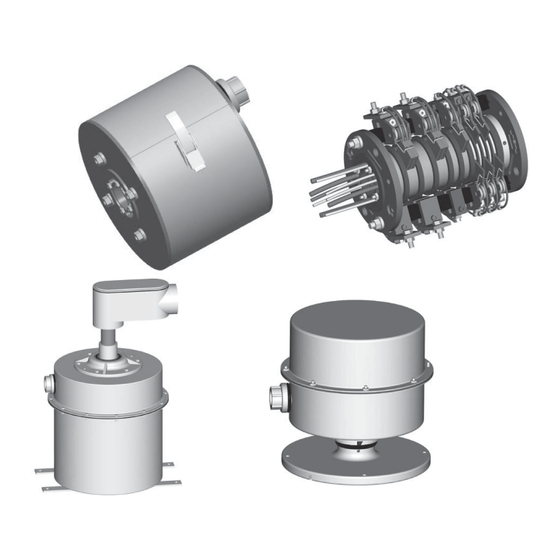
- Page 1 R Series Slip Rings Installation, Operation & Maintenance Manual XA-969000.9 - 01.13.23 R SERIES SLIP RINGS MANUAL...
- Page 2 Buyer’s name - provided that Seller shall have the right to elect to defend any such suit or action for the account of Buyer. The foregoing shall be the exclusive remedies of the Buyer and all persons and entitles claiming through the Buyer. R SERIES SLIP RINGS MANUAL...
- Page 3 Ask us for a quote on expert system installations,inspections, preventative maintenance, and repairs/retrofits. As the world’s largest single source manufacturer of mobile electrification products, Conductix-Wampfler has the unique ability to offer a degree of service not found anywhere else. Conductix-Wampfler’s team of highly qualified service technicians and engineers have years of experience servicing our complete line of products.
-
Page 4: Table Of Contents
4.5 Brush Springs 4.6 Rings 4.7 Electrical Connections 4.8 Brush Rigging 4.9 Enclosure Inspection 4.10 Cleaning SECTION 5 - STORAGE SECTION 6 - SERIAL NUMBER RECORD SECTION 7 - TROUBLESHOOTING SECTION 8 - REPLACEMENT PARTS 20-24 NOTES R SERIES SLIP RINGS MANUAL... -
Page 5: Section 1 - Safety
1.2.3 The obligations agreed upon in the delivery agreement and our General Terms and Conditions of business apply, as do the delivery conditions of the manufacturer and the legal regulations applicable at the time the contract was concluded. 1.2.4 All products are subject to technical modifications in the context of improvement of function and further development. R SERIES SLIP RINGS MANUAL... -
Page 6: Personnel Requirements-Qualifications
Unauthorized persons who do not meet the requirements described here are not acquainted with the dangers in the working area. Keep unauthorized personnel away from the working area. In case of doubt, address the person and direct them away from the working area. Stop working, as long as unauthorized persons are in the working area. R SERIES SLIP RINGS MANUAL... -
Page 7: Personnel Requirements-Training
1.8 Operational Warnings 1.8.1 Slip rings must be enclosed and protected from any contact by personnel. Means for the provision of this protection is the responsibility of the user. Various enclosure styles are available from Conductix-Wampfler. WARNING •... -
Page 8: Maintenance Warnings
1.10.1 The R-Series slip ring are built to manufacturer’s interpretation of NEC guidelines and UL specifications. They are not generally certified or listed by an independent certifying or regulatory body. 1.10.2 The following specifications apply to all R-Series slip rings (contact Conductix-Wampfler for in-between sizes). Bore Size (in.) -
Page 9: Section 2 - Product Disposal
All other components are to be disposed of in accordance with their material composition. Take care with items identified as Substances of Concern. 2.0.3 Local authorities or special disposal companies can provide information about environmentally appropriate disposal. R SERIES SLIP RINGS MANUAL... -
Page 10: Section 3 - Installation
The “loose link” or “floating” type drive connection or mechanism is required due to run-out and or deflection that may occur during operation. • If not followed, premature wear or failure of slip ring assembly will occur. (See 8.0 REPLACEMENT PARTS for optional bolt on drive brackets). R SERIES SLIP RINGS MANUAL... -
Page 11: Unenclosed Slip Ring Assemblies And Slip Ring Assemblies With Wrap Around Covers
Consult factory for special or other bore sizes. Set Screw Insulator Brush Holder Figure 3-1 Brush Core lead terminal block and terminal strip Drive Holes Drive Link or Pin (supplied by others) Minimum Clearance .030” Figure 3-2 R SERIES SLIP RINGS MANUAL... -
Page 12: Slip Ring In Revolving Covers (Ru)
This is to be “play” between the slip ring driven item and the device that is driving it. (See Section 8.0 REPLACEMENT PARTS for optional bolt on drive brackets). R SERIES SLIP RINGS MANUAL... -
Page 13: Explosion Proof Enclosures (Xru, Xsu, And Xsu With Optional Air Pass)
This is to avoid putting strain on the assembly due to the run-out and or deflection that may occur during operation. This is to be “play” between the slip ring and the device that is driving it. R SERIES SLIP RINGS MANUAL... -
Page 14: Wiring And Connections
If the thermostat is supplied separate from the heater, the thermostat is to be wired in series with the power lead. WARNING During installation of the slip ring, proper air gap must be maintained between conductive items, and all terminal • connections. Refer to U.L. 508C standards. Figure 3-5 R SERIES SLIP RINGS MANUAL... -
Page 15: Section 4 - Maintenance
1. Remove the brush shunt lead and brush lead wiring from top of brush holder by removing top terminal screw. 2. Lift spring slightly with a hook type tool. 3. Tilt brush out from under the spring and away from holder for removal. 4. To reassemble, replace the brush in the reverse fashion. R SERIES SLIP RINGS MANUAL... - Page 16 3. Slide the remaining brush assembly frame out from under the brush post. 4. To reassemble, replace assembly in the reverse fashion. Torque clamp bolts to 96 in lbs. Clamp Brush Post Shunt Leads Spring Frame 200 Amp Brush Figure: 4-2 R SERIES SLIP RINGS MANUAL...
-
Page 17: Brush Fit Inspection
1.5 lbs. minimum 3.0 lbs. minimum 5 lb. Scale 2.5 lbs. minimum Brush Spring Figure: 4-4 NOTE: • If bush posts are mounted separate from slip ring assembly, follow manufacturer’s recommendation on mounting distance from rings. R SERIES SLIP RINGS MANUAL... -
Page 18: Rings
4.10.1 In addition to using the slip ring polishing kit No. XA-41286 clean the slip ring using only clean, dry, low pressure air or a vacuum cleaner to remove the contaminants from the rings. Do not use any solvents, aerosol sprays, or liquid cleaners on the slip ring assembly. R SERIES SLIP RINGS MANUAL... -
Page 19: Section 5 - Storage
Intermittent Signal or Loss of Signal. (Ring Polishing Kit No. XA-41286) Visually check for spring fit and function. Adjust or replace as necessary. consider silver graphite brushes and/or silver plated rings for sensitive data signals and very low amp/volt signals. R SERIES SLIP RINGS MANUAL... -
Page 20: Section 8 - Replacement Parts
2.5”, 3.0” Figure 8-1 Figure 8-2 Spare Parts overview (1.5” Bore Ring show, other bore size parts may differ slightly. Contact factory for questions). NOTE: • Always have Part and or Serial Number when ordering R SERIES SLIP RINGS MANUAL... - Page 21 XA-30073 XA-R515-DTK-6 XA-R559/R469-8A-6 8.0” XA-30076 XA-R1345 XA-100210 10.0” XA-30076 XA-R1345-10000M N/A XA-100186 Special bore sizes: Consult Factory C/F = Consult factory if assembly is equipped with ball bearings, wrap around cover, or other special features. R SERIES SLIP RINGS MANUAL...
- Page 22 XA-R469-4A-4.5 XA-R469-4A-5000 XA-R469-4A-6000 XA-R1191-8 XA-R1191-8-10000 200A/600V XA-R469-8A-4.5 XA-R469-8A-5000 XA-R469-8A-6000 XA-R1191-8 XA-R1191-8-10000 225A/600V XA-R469-8A-4.5 XA-R469-8A-5000 XA-R469-8A-6000 XA-R1191-8 XA-R1191-8-10000 300A/600V XA-R469-8A-4.5 XA-R469-8A-5000 XA-R469-8A-6000 XA-R1191-8 XA-R1191-8-10000 400A/600V XA-R469-8A-4.5 XA-R469-8A-5000 XA-R469-8A-6000 XA-R1191-8 XA-R1191-8-10000 600A/600V XA-R469-8A-4.5 XA-R469-8A-5000 XA-R469-8A-6000 XA-R1191-8 XA-R1191-8-10000 R SERIES SLIP RINGS MANUAL...
- Page 23 XA-R469-8M-4500 XA-R469-8M-5000 XA-R469-8M-6000 XA-R1191-8M XA-R1191-8M-10000 200A/600V XA-R469-8M-4500 XA-R469-8M-5000 XA-R469-8M-6000 XA-R1191-8M XA-R1191-8M-10000 225A/600V XA-R469-8M-4500 XA-R469-8M-5000 XA-R469-8M-6000 XA-R1191-8M XA-R1191-8M-10000 300A/600V XA-R469-8M-4500 XA-R469-8M-5000 XA-R469-8M-6000 XA-R1191-8M XA-R1191-8M-10000 400A/600V XA-R469-8M-4500 XA-R469-8M-5000 XA-R469-8M-6000 XA-R1191-8M XA-R1191-8M-10000 600A/600V XA-R469-8M-4500 XA-R469-8M-5000 XA-R469-8M-6000 XA-R1191-8M XA-R1191-8M-10000 R SERIES SLIP RINGS MANUAL...
- Page 24 Barrier Part Number: XA-R27-B Item #10 Z-Ring Consult Factory for individual replacement rings Item #11 Brush Post Bolts Consult Factory for replacement brush holder bolts Item #12 Core Bolts Consult Factory for replacement core bolts R SERIES SLIP RINGS MANUAL...
-
Page 25: Notes
NOTES R SERIES SLIP RINGS MANUAL... - Page 26 (+52 81) 1090 9025 (+52 81) 1090 9013 Phone +1-402-339-9300 Phone +1-450-565-9900 +1-402-339-9627 +1-450-951-8591 (+52 81) 1090 9014 Fax (+55 11) 4813 7330 info.us@conductix.com info.ca@conductix.com info.mx@conductix.com info.br@conductix.com latinamerica@conductix.com Contact us for our Global Sales Offices R SERIES SLIP RINGS MANUAL XA-969000.9 - 01.13.23...
Need help?
Do you have a question about the R Series and is the answer not in the manual?
Questions and answers