
Related Manuals for Conductix-Wampfler Hevi-Bar II


Summary of Contents for Conductix-Wampfler Hevi-Bar II
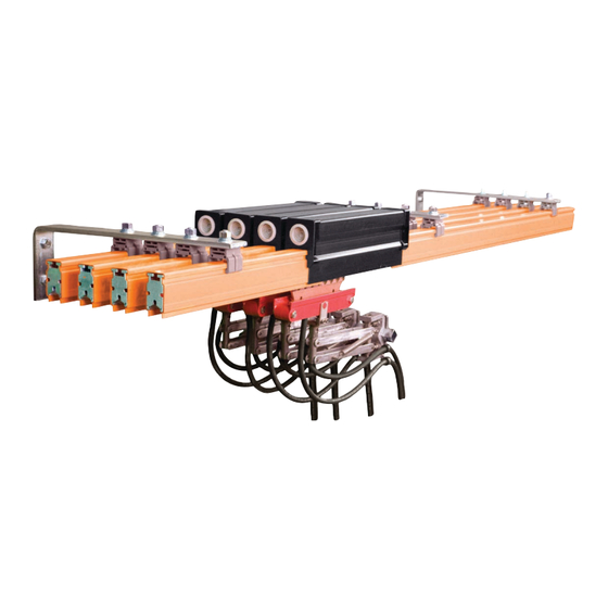
- Page 1 Conductor Bar Systems Hevi-Bar II Manual XA-968800.5 | 05-02-23 HEVI-BAR II CONDUCTOR BAR MANUAL...
- Page 2 Buyer’s name - provided that Seller shall have the right to elect to defend any such suit or action for the account of Buyer. The foregoing shall be the exclusive remedies of the Buyer and all persons and entitles claiming through the Buyer. HEVI-BAR II CONDUCTOR BAR MANUAL...
- Page 3 Ask us for a quote on expert system installations,inspections, preventative maintenance, and repairs/retrofits. As the world’s largest single source manufacturer of mobile electrification products, Conductix-Wampfler has the unique ability to offer a degree of service not found anywhere else. Conductix-Wampfler’s team of highly qualified service technicians and engineers have years of experience servicing our complete line of products.
-
Page 4: Table Of Contents
7.2 Tools Needed 7.3 Optional Tools (Not Required) 7.4 Anchor Pin Installation 7.5 Anchor Clamp Installation SECTION 8 - CONDUCTOR BARS 8.0 Locations 8.1 Tools Needed 8.2 Conductor Bar Kit Contents 8.3 Conductor Installation 19-20 HEVI-BAR II CONDUCTOR BAR MANUAL... - Page 5 13.1 Tools Needed 13.2 Strong Back Assemblies Contents 13.3 Installation SECTION 14 - COLLECTORS 14.0 Locations 14.1 Tools Needed 14.2 Collector Kit Contents 14.3 Installation 14.4 Leveling Spring Installation for Lateral Mount Collectors Overview 14.5 Installation 32-36 HEVI-BAR II CONDUCTOR BAR MANUAL...
- Page 6 17.9 End Caps 17.10 Collectors 42-43 17.10.1 Collector Arms 17.10.2 Mounting Brackets and Bolts 17.10.3 Tension Springs 17.10.4 Spring Pins 17.10.5 Cables 17.11 Shoe Holders 17.12 Collector Shoe Replacement SECTION 18 - TROUBLESHOOTING 45-46 NOTES HEVI-BAR II CONDUCTOR BAR MANUAL...
-
Page 7: Section 1 - Safety
1.2.3 The obligations agreed upon in the delivery agreement and our General Terms and Conditions of business apply, as do the delivery conditions of the manufacturer and the legal regulations applicable at the time the contract was concluded. 1.2.4 All products are subject to technical modifications in the context of improvement of function and further development. HEVI-BAR II CONDUCTOR BAR MANUAL... -
Page 8: Personnel Requirements-Qualifications
Keep unauthorized personnel away from the working area. In case of doubt, address the person and direct them away from the working area. Stop working, as long as unauthorized persons are in the working area. HEVI-BAR II CONDUCTOR BAR MANUAL... -
Page 9: Personnel Requirements-Training
Breathing mask (FFP-3 - according to country-specific requirements): For protection against materials, particles, and organisms. In this case, for protection against the dust produced by the abrasion of carbon brushes and the PVC insulation of the conductor rail. HEVI-BAR II CONDUCTOR BAR MANUAL... -
Page 10: Section 2 - Product Disposal
All other components are to be disposed of in accordance with their material composition. Take care with items identified as Substances of Concern. 2.0.3 Local authorities or special disposal companies can provide information about environmentally appropriate disposal. HEVI-BAR II CONDUCTOR BAR MANUAL... -
Page 11: Section 3 - Overview
Noalox oxide inhibiting grease must be applied to the surface and then the components bolted together. The oxide inhibiting grease prevents oxide buildup and provides low-resistant connection. 3.0.4 Hevi-Bar II can be used indoor or outdoor with insulated hangers. The operating temperature range is -40°F to +250°F (up to +280°F with high-heat covers on 700A and 1000A Conductors Only). -
Page 12: Typical 3-Phase System Overview
SECTION 3 - OVERVIEW 3.1 Typical 3-Phase System Overview HEVI-BAR II CONDUCTOR BAR MANUAL... -
Page 13: Environmental Considerations
Two wire brushes, ground, and runway level • Linoleum knife • A measuring tape • Scotch Brite Pads (or equivalent) to clean mating surfaces of bar • Open end/box end combination 3/8”, 7/16”, 1/2”, 9/16”, and 16 mm wrenches HEVI-BAR II CONDUCTOR BAR MANUAL... -
Page 14: Section 4 - General Assembly Instructions
3. Conductix-Wampfler recommends the first accessible conductor being the ground conductor (if applicable). 4. Move down the runway, install the next inboard conductor and join it to the corresponding conductor installed in step 2. - Page 15 10. Install power feeds on conductor bars per layout and the instructions in Section 11 - Power Feed Assembly Kits. 1.50 3.75 (95.25) (38.1) 500 Amp 1.36 (34.5) 1.50 4.25 (107.95) (38.1) 700 Amp 1.75 (44.45) 1.50 6.00 (152.40) (38.1) 1000 Amp 2.33 (59.18) 1.50 6.00 (152.40) (38.1) 1500 Amp 3.00 (76.20) Figure 4-1 HEVI-BAR II CONDUCTOR BAR MANUAL...
-
Page 16: Section 5 - Support Brackets
1. To weld the web bracket to the support structure simply position the web bracket and tack weld to the beam. 2. After ensuring that the bracket is mounted at the correct height and level, proceed to fillet weld the bracket to the support structure. Figure 5-1 Figure 5-2 Figure 5-3 Figure 5-4 HEVI-BAR II CONDUCTOR BAR MANUAL... -
Page 17: Section 6 - Hanger Clamps
700 Amp 1.75” 4.63” Polycarbonate Snap-In w/ insulator 25-26 ft-lbs. 1000 Amp 2.25” 5.13” Stainless Steel Cross Bolt 38-39 ft-lbs. 1500 Amp 3.13” 6.00” Stainless Steel Cross Bolt w insulator 25-26 ft-lbs. Table 6-1 Table 6-2 HEVI-BAR II CONDUCTOR BAR MANUAL... -
Page 18: Section 7 - Anchor Clamps
1. For systems using hanger clamps with cross bolts, torque the nuts on the hanger clamp to 60 in.-lbs at anchor locations only. Anchor pins are not required. XA-23946 0.41 (10.41) 500A 0.47 (11.93) 700-1500A 2.0 (50.8) Figure 7-1 HEVI-BAR II CONDUCTOR BAR MANUAL... -
Page 19: Section 8 - Conductor Bars
It is best to hoist 30ft. lengths with three ropes. 7. Install the first section in the clamps nearest the web of the beam. One person should be handling the bar at each hanger clamp location. Snap-in Hanger Cross Bolt Hanger Figure 8-1 HEVI-BAR II CONDUCTOR BAR MANUAL... - Page 20 13. Check clamps to see that they have not rotated and that they are still square with the bar. Hanger Type Bolt Torque Specification Polycarbonate Snap-In 15 ft-lbs. Polycarbonate Snap-In w/ 25-26 ft-lbs. insulator Stainless Steel Cross Bolt 38-39 ft-lbs. Stainless Steel Cross Bolt w 25-26 ft-lbs. insulator Table 8-2 HEVI-BAR II CONDUCTOR BAR MANUAL...
-
Page 21: Section 9 - Splice Assembly Kits
6. Slide end plugs (if assembly has end plugs) onto conductor bars. Place overlap cover into position, centered over splice plate. Snap end plugs into the holes in the overlap cover. Ensure end plugs are seated correctly.. Figure 9-1 HEVI-BAR II CONDUCTOR BAR MANUAL... -
Page 22: Section 10 - Expansion Section Kits
5. After the gap has been set, anchor the conductor. NOTE: • For other temperature ranges see installation drawings or consult factory for gap settings. (2.00) TOTAL GAP SETTING - 2 TOTAL GAP SETTING Figure 10-1 HEVI-BAR II CONDUCTOR BAR MANUAL... - Page 23 (115.5) (106.2) (97) (87.7) (78.5) (69.3) (60) (50.8) 6.00 5.64 5.27 49.1 4.55 4.18 3.82 3.45 3.09 2.73 2.36 2.00 (-23.3) (154.2) (143.2) (133.9) (124.7) (115.5) (106.2) (97) (87.7) (78.5) (69.3) (60) (50.8) Table 10-1 HEVI-BAR II CONDUCTOR BAR MANUAL...
-
Page 24: Section 11 - Power Feed Assembly Kits
Medium Heat 350 MCM XA-32500 Medium Heat 500 MCM XA-50067 Medium Heat 1000 500 MCM XA-38184D Medium Heat 1500 500 MCM XA-50227C High Heat 500 MCM XA-24594 Table 11-1 High Heat 1000 500 MCM XA-23530 HEVI-BAR II CONDUCTOR BAR MANUAL... -
Page 25: 500 Amp Installation
700 Amp 11.76 (298.6) 2.60 (65.9) 5.25 (133.4) Cable and Lug Supplied by Others 4.49 (114.1) 1000 Amp 17.50 (444.5) 2.53 (64.26) 9.50 (241.3) Cable and Lug Provided by Others 4.17 (105.91) 1500 Amp Figure 11-1 HEVI-BAR II CONDUCTOR BAR MANUAL... - Page 26 8. Assemble power feed plate and cable on the top of conductor using hardware provided. If hardware is stainless steel apply anti- seize to end of bolts before assembly of nuts. Torque to 10-11 ft-lbs. 9. Snap cover (centered) over power feed cable assembly, slide end plugs (if assembly has end plugs) into power feed cover. HEVI-BAR II CONDUCTOR BAR MANUAL...
-
Page 27: Section 12 - Power Interrupting Section Kits
NOTE: • A detailed schematic can be seen in Figure 12-2. • A standard air gap for isolation is 1.0”, is recommended that 2.0” air gap is used for outdoor and dusty / dirty environments. HEVI-BAR II CONDUCTOR BAR MANUAL... - Page 28 6.0 (152.4) 1.0 (25.4) Gap 1.0 (25.4) Gap 9’ 7.9” (2.94 M) 9’ 8.25” (2.95 M) 9’ 7.9” (2.94 M) 30.0’ (9.14 M) Cable and Lug Cable and Lug by Others Figure 12-1 by Others HEVI-BAR II CONDUCTOR BAR MANUAL...
- Page 29 Power Flow (Switch Open) 30.00" (762) Power Flow (Switch Open) Maintenance Zone Min Bu er Zone Isolation Switch (Closed) Isolation Splice (P) Power Feed (3) Maintenance Zone Power Flow (Switch Open) Power Zone Figure 12-2 HEVI-BAR II CONDUCTOR BAR MANUAL...
-
Page 30: Section 13 - Strong Back Assemblies
1. The top hanger mount must be checked for a max torque of 39 ft-lbs. 2. The cross bolts will be finger tight or max torque of 5 ft-lbs. depending on placement of strong back. 30.00 (762) 1.25 (31.75) 11.00 (279.4) 1.25 (31.75) 11.00 (279.4) Figure 13-1 HEVI-BAR II CONDUCTOR BAR MANUAL... -
Page 31: Section 14 - Collectors
14.4.4 The hook end of the spring will always wrap around the outside of the collector arms. The spring body should never be installed between the arms of the collectors. Mounting Base Material Torque Value Plastic 8-10 Ft-Lbs. Aluminum 18-20 Ft-Lbs. Stainless Steel 18-20 Ft-Lbs. Table 14-1 HEVI-BAR II CONDUCTOR BAR MANUAL... -
Page 32: Installation
See Figures on the following pages for reference. Amperage Collector Part Number Pigtail Part Number Pigtail Gauge XA-30388 XA-28063 4 AWG 700-1500 XA-24061 XA-28063H 2 AWG Table 14-2 XA-560481 Angled End Hook End Figure 14-1 HEVI-BAR II CONDUCTOR BAR MANUAL... - Page 33 34.24 (869.8) MOVEMENT CONTACT SURFACE 2.75 (69.9) MOVEMENT 6.00 (152.9) MOVEMENT 2.15 (54.6) 24.24 (615.8) Figure 14-2 - XA-HB2C-600T-42-LATL 16.11 (409.19) 2.75 (69.85) 11.0 (279.4) MOVEMENT CONTACT SURFACE 2.75 (69.85) MOVEMENT (152.4) Figure 14-3 - XA-31933 HEVI-BAR II CONDUCTOR BAR MANUAL...
- Page 34 14.36” (364.74) 2.75” (69.85) Contact Surface 2.75” (69.85) 5.50” (139.7) Figure 14-4 XA-HB2C-250T-21 1.50 (38.1) MOVEMENT 1.50 (38.1) MOVEMENT 30.51 (774.9) 2.75 (69.9) MOVEMENT CONTACT SURFACE 2.75 (69.9) MOVEMENT 5.50 (139.7) 7.65 (194.4) Figure 14-5 HEVI-BAR II CONDUCTOR BAR MANUAL...
- Page 35 (69.9) (63.5) (63.5) Contact Surface 2.75 (69.9) (152.4) 8.08 (205.2) Figure 14-7 XA-HB2C-400T-42 34.24 (869.7) 2.50 2.50 17.12 2.75 (69.9) (63.5) (63.5) (434.8) MOVEMENT CONTACT SURFACE 2.75 (69.9) MOVEMENT 6.00 (152.4) 8.11 (206) Figure 14-8 HEVI-BAR II CONDUCTOR BAR MANUAL...
- Page 36 SECTION 14 - COLLECTORS Mounting 3.00” Bracket by (76.2) Others Refer to Table 6-1 for Dimension Contact Surface 6.00” (152.4) 1.00” Sq Bar By Others Mounting Hevi-Bar II Collector P/N: XA-24061 Figure 14-9 HEVI-BAR II CONDUCTOR BAR MANUAL...
-
Page 37: Section 15 - Standard Heat End Cover Kits
6. While shrink tubing is warm, press and flatten the excess tubing starting approximately 0.75” (19mm) behind end of bar. 7. When tubing has cooled cutoff excess tubing, leaving approximately 0.75” (19mm) of flattened tubing. HEVI-BAR II CONDUCTOR BAR MANUAL... -
Page 38: 1000 Amp / 1500 Amp
6. While shrink tubing is warm, press and flatten the excess tubing starting approximately 0.75” (19mm) behind end of bar. 7. When tubing has cooled cutoff excess tubing, leaving approximately 0.75” (19mm) of flattened tubing. 2.75” (69.85) 1.50” (38.1) 6.00” (152.4) 4.00” (139.7) Figure 15-1 HEVI-BAR II CONDUCTOR BAR MANUAL... -
Page 39: Section 16 - High Heat End Cover Kits
4. Position clamp underneath bar approximately 3.0” (76mm) from end and tighten 5/16” flexloc nut with a 1/2” open end wrench until cover is firm. 2.53” 16.00” (406.4) (64.26) 6.94” (176.27) Conductor Assy. Part No. XA-24554 Ref. 2.13” 7.50” (190.5) (54.10) Figure 16-1 HEVI-BAR II CONDUCTOR BAR MANUAL... -
Page 40: 1000 Amp
4. Torque nut with torque wrench to 10-11 ft-lbs. 5. Snap overlap cover assembly, with short end toward conductor bar, over conductor bar and cover with “L” shape clamp positioned between overlap cover pins. 2.50” 16.00” (406.4) (63.5) 5.24” (133.09) Figure 16-2 HEVI-BAR II CONDUCTOR BAR MANUAL... -
Page 41: Section 17 - Inspection And Maintenance
All power must be disconnected from the conductor bar prior to performing any inspection or maintenance. Proper lockout/tag- out procedures must be followed. Should questions or concerns arise regarding the condition of the system or its components, call Conductix-Wampfler at: (800) 521 4888 17.1 Frequency... -
Page 42: Splices
Inspect for cracks, deformation, or any other evidence of damage. Collector arm should be replaced at least every 5 years. 17.10.2 Mounting Brackets and Bolts • Verify collector mounting base is square on the vehicle and it is aligned with the conductor. HEVI-BAR II CONDUCTOR BAR MANUAL... -
Page 43: Tension Springs
Spring is properly positioned on the pin in the collector arm. Check contact force and nominal distance between the mounting surface and contact surface (contact Conductix-Wampfler for force requirement). A “fish scale” may be used to check this. Hook the scale on the collector arm as close to the shoe-end of the collector. -
Page 44: Collector Shoe Replacement
Under severely corrosive conditions, the copper graphite shoes my be corroded to the point where less than half of the shoe is remaining, decreasing the available contact surface area and causing overheating and pitting. 4. Infrequent maintenance of the collectors can lead to worn-out shoes, poor contact, pitting etc. HEVI-BAR II CONDUCTOR BAR MANUAL... -
Page 45: Section 18 - Troubleshooting
Expansion gap set incorrectly to the gap setting chart. Check torque of the hardware on the anchor. Re-torque as required. Anchor clamp not tight Check anchor clamps and verify none are cracked or fractured. Replace as necessary. HEVI-BAR II CONDUCTOR BAR MANUAL... - Page 46 Incorrect position of tension spring on in base so spring is pulling the collector Uneven shoe wear on sides of shoe collector shoe into the conductor and “up” from the running surface (refer to collector drawing). HEVI-BAR II CONDUCTOR BAR MANUAL...
-
Page 47: Notes
NOTES HEVI-BAR II CONDUCTOR BAR MANUAL... - Page 48 (+52 81) 1090 9025 (+52 81) 1090 9013 Phone +1-402-339-9300 Phone +1-450-565-9900 +1-402-339-9627 +1-450-951-8591 (+52 81) 1090 9014 Fax (+55 11) 4813 7330 info.us@conductix.com info.ca@conductix.com info.mx@conductix.com info.br@conductix.com latinamerica@conductix.com Contact us for our Global Sales Offices HEVI-BAR II CONDUCTOR BAR MANUAL XA-968800.5 | 05-02-23...
Need help?
Do you have a question about the Hevi-Bar II and is the answer not in the manual?
Questions and answers